How to make a belt sander
Many home craftsmen and professionals are wondering how to make a grinding machine with their own hands.
The reason for this question is quite simple: the high cost of serial grinding equipment, which not everyone can pay off if not used regularly. In order to make such equipment, you will need several main components: an electric motor, rollers and a reliable frame. Naturally, drawings of such a device or a photo of it would not be superfluous. Also at the end of the article you can watch videos on assembling a tape machine on your own. The motor for belt grinding equipment is not difficult to find; it can be removed from an old washing machine. You will have to make the frame yourself; for this you can use a sheet of metal with dimensions 500x180x20 mm. One side of the frame should be cut very evenly, since it will be necessary to attach the platform on which the electric motor will be mounted to it. The platform for the electric motor should also be made of a sheet of metal with dimensions 180x160x10 mm. Such a platform must be secured to the frame very securely using several bolts.
Another version of the bed
The efficiency of a belt sanding machine directly depends on the characteristics of the electric motor that is installed on it. If you are planning to make a grinding machine with your own hands, then an electric motor with a power of 2.5–3 kW, developing about 1500 rpm, is quite suitable for you. In order for the sanding belt to move at a speed of 20 m/s when using such a motor, the drums must have a diameter of about 200 mm. What’s convenient is that if you choose an engine with these characteristics, you won’t need to make a gearbox for your grinding machine.
The drive shaft is connected directly to the electric motor shaft, and the second - driven - must rotate freely on an axis, which is installed in bearing units. In order for the abrasive belt to touch the surface of the workpiece more smoothly, the section of the frame on which the driven shaft is installed should be made with a slight bevel.
You can make shafts for a belt sanding machine from a chipboard with minimal financial costs. Simply cut square blanks of 200x200 mm in size from such a plate, drill central holes in them and place them on the axle with a package with a total thickness of 240 mm. After this, all you have to do is grind the resulting package and make it into a round shaft with a diameter of about 200 mm.
Drawings and detailed analysis of some parts of a machine made of wood.
Wood belt sander (click to enlarge)
In order for the tape to be located strictly in the middle of the shaft, the diameter of its central part should be 2–3 mm larger than at the edges. And to prevent the tape from slipping on the drum, it is necessary to wrap a layer of thin rubber on it, for which you can use an old tire from a bicycle wheel, having previously cut it along its entire length.
The sanding belt for such a machine, the optimal width of which should be 200 mm, is made from ordinary emery cloth. The standard cloth is cut into strips of the required width, and an abrasive tape is already glued from them. It should be borne in mind that the material is glued end-to-end; for this purpose, dense material is placed on the reverse side, which will strengthen the resulting seam. The properties of such a seam are greatly influenced by the glue; it must be of very high quality, then the material will not tear along the seam after a short period of use.
Several more options for manufacturing belt grinding machines can be seen in the video below.
https://youtube.com/watch?v=opM1afRob6o
Creating a belt sanding machine
In fact, there are only two main assemblies for a belt sanding machine - one with a vertical placement of the working part of the abrasive belt, as well as a horizontal one. Among those who make grinding machines, the first option is popular because the device is suitable for many types of processing processes, and is even more convenient for sharpening tools. In addition, dust is discharged downward during the process. Most craftsmen often use not metal, but wood or even plywood as the material for creating the frame, rollers and main parts.
The wood option has many advantages:
- All components and parts can be made in a carpentry workshop.
- Adjusting wood parts is much easier.
- Wooden construction is lighter.
- The device is vibration-resistant and can be easily disassembled if necessary.
In order to independently manufacture a reliable, efficient and safe grinding machine, you should have at least minimal engineering knowledge and skills in processing construction materials. For this reason, further we will consider only the very important aspects of creating and assembling the machine, and its schematic layout is presented in the picture below.
Selection of electric motor
As a drive for a homemade grinding machine, or rather a machine, they usually use electric motors from drum washing machines that have failed, as well as hand-held electric tools. If we talk about the former, their power is usually approximately 0.3 kW with a rotation speed of approximately 3000 rpm.
They are convenient for installation work, as they are equipped with special fastening lugs on the body with holes, as well as a thread on the shaft for a pulley attachment. Electric tools (as a rule, we are talking about grinders and drills) are attached to brackets or removable clamps. Their motors will operate at higher frequencies, and for this reason, in grinding machines, the best option would be to use models where it is possible to adjust this parameter.
In a drill grinder, the speed of the electric drive is one of the most important characteristics of a homemade machine, because the diameter of the drive pulley, which transmits the rotation of the sanding belt, will be calculated from it. All types of abrasive belts are designed for use at a certain linear speed, and its indicators are measured in m/s, and the operating speed will be equal to the peripheral speed of the drive pulley.
For this reason, if you have an electric motor with known data, the creation of a grinding machine project must necessarily begin with the fact that you decide on the diameter.
Please note that based on the length of the sanding belt and the diameter of the pulleys and rollers, you can calculate their center-to-center distances, and also determine the overall size of the future grinding machine.
Frame (bed) and its structure
Now a little about the frame. It is also called the frame of a grinding machine, and it is a supporting structure on which the electric drive, rollers and pulleys are mounted. The normal movement of the abrasive belt, as well as the stability of the device, will depend on its rigidity and precise manufacturing. The contours of the frame, as a rule, repeat the pattern of rollers (called kinematic), which are located at its extreme points.
After this, its design will be examined using the example of a homemade device made of plywood and wood, in which an electric drill is used as a drive. You can see the process of creating such a grinding machine in detail in the video, and at the end you will find sketches of all the parts in real sizes.
The machine bed is a box-type structure, with a drive pulley and a pair of rollers located inside it. It is made of a broken-shaped side panel in the shape of the letter “C”, which is installed on a large base. The material used for each part of such a grinding machine is plywood with a large thickness.
A work table with a slot for an abrasive belt is attached to the lower ledge of the bed. The drive pulley is installed on the vertical part of the frame, and the guide roller is installed at the end of the bottom; the regulating and tensioning element is located at the top. A similar figured sidewall is attached to the hinges in the form of a door, and also fully covers the entire space with the rollers and pulley.
The huge advantage of such a belt sanding device is that all its parts are made using the simplest tools in a carpentry workshop, and during the assembly process a minimum number of types of fasteners and metal components are used. As you can see, the master will spend no more than 2 days on its production.
Please note that if you look at everything from a safety point of view, then the solution to completely cover the rollers and belts is optimal. And the noticeable disadvantages of such a machine include only a small amplitude of the belt tension.
Roller installation
Homemade and factory-made belt sanding machines usually use 2 to 4 rollers of different sizes. One of them will always be a pulley on the drive axis and constantly transmits movement to the sanding belt. Another one will act as a tensioner (sometimes this function is combined with axial adjustment).
The rest are guides and are also capable of adjustment. One of the most popular is the design of grinding machines, which have three rollers. In this case, everyone will perform one of the functions. In such a configuration, when the working part of the abrasive belt for grinding is placed vertically, there will be a tension roller at the top and a guide roller at the bottom.
A belt grinder made from a drill with your own hands also needs to be configured. To do this, after installing the rollers and pulley, it is necessary to carry out adjustments on the machine frame. During operation, the sanding belt will move at a speed of 10-30 m/s, and every deviation in the geometry of the relative placement of the rollers and pulley can cause breakage and derailment.
For this reason, their axes must be set exactly parallel to the horizontal, and the planes of rotation along which the tape will advance must clearly coincide in the verticals. The possibility of such adjustments must be foreseen in advance during the development of the design of a belt grinding machine.
Brief instructions
Despite the simplicity of the design, such a machine will always cope with all the tasks assigned to it, and if you do not have funds in your budget to buy a factory machine, then a homemade device will be an excellent assistant for you. First, you need to use a crown to cut out 6 thick round parts and four thinner round pieces.
Although in this case all the calculations are based on how thick the sandpaper is (which can also be made as you go), you can modify such a machine and adapt it to your needs. In addition to the round parts, you will need a hairpin on which you will string the circles. Next, you need to glue the round parts together and glue them to a metal pin. As a result, new parts will be obtained.
Next, take a couple of small pieces of plywood and make a small diameter hole in one for self-tapping screws, and in the second, drill a hole for the nut with a pen. All that remains is to drop a little epoxy resin and hammer into the nut. Next, coat the edge of the second part with adhesive, and connect both parts to each other, secure with self-tapping screws. You should also make a couple more holes on the part you won't be drilling on.
Four such connections should be made. Afterwards we make a belt for sanding, and for this you need to cut off regular sandpaper as in the photo, apply glue to the inside and fasten it to the fabric. Then start assembling the machine. Make holes on the plywood, secure the first part with bolts and put one of the “drums” on it.
Then support the drum with the second part and secure it with the bolts. For such a drum, the pin on the inside should be longer - this is where you will connect the drill. On the other side we do the same, but here we will use parts with oblong holes.
Next, fix the rectangle with the circle cut out in it, insert the device into the mounting socket and connect the pin to the drill chucks. All that remains is to fix the pin in the socket and that’s it, the device is ready!
Making a grinder from a computer hard drive + (Video)
Any old hard drive can be converted into a miniature grinding machine. To do this you need to follow these steps:
- completely disassemble the hard drive and remove from the case everything that is located to the left of the magnetic disks;
- cut out a working circle from sandpaper, make a hole in the center of the circle for the spindle;
- stick several strips of double-sided tape onto the rotating disk of the hard drive and secure it with sandpaper;
- make a protective screen to protect the eyes from the possible ejection of the manufactured sanding disc;
- connect the finished design to the power supply from the computer and use it.
Of course, this design does not have high power, but it is quite possible to sharpen a small knife or scissors.
Making a belt sander with your own hands + (Video)
Making a belt sander yourself is not at all difficult; you need to complete the following steps:
- select suitable materials and parts;
- create a reliable basis for securing the tool;
- install a suitable tabletop;
- secure the vertical posts with tensioner and drum;
- mount the motor and drums;
- secure with sanding tape.
To process fairly large parts and elements, it is necessary to make a large copy of a serial grinder. For example, if you take an electric motor with a power of 2 kW or more powerful with a rotor speed of 1500 rpm, then you don’t need to install a gearbox. The power of such an engine is quite enough to rotate a drum about 20 cm in diameter and process parts of about 2 m.
You can also use an electric motor from an old washing machine. In this case, the frame is made from a thick sheet of iron, preparing a place for installing the motor and carefully securing it with bolts to eliminate vibration. The design of such a machine consists of 2 drums, one of which is fixed, and the second can be tensioned and rotates on bearings around an axis. It is advisable to make the base for the machine from metal or several sheets of thick plywood. The drums are made on a lathe from chipboard. The tape is cut from sandpaper sheets about 20 cm wide and secured to the frame. The larger the table size, the larger the parts can be stacked and processed in the future. Drawings of finished products can be found online.
Preparing for work
Before starting work, you need to think through the sequence of all technological operations in the manufacture of a homemade machine, plan the manufacturing technology, decide on future materials and tools that will be needed during the work process.
Tool
To make a machine from a drill or screwdriver, you will need the following tool:
- Circular saw or sawing machine.
- Jigsaw.
- Angle grinder (angle grinder or simply “grinder”).
- Drill or screwdriver.
- Grinding machine.
- Various hand tools: hammer, screwdriver, clamps, wood core drill (or simply “crown”), square, marking pencil, etc.
Material and components
To make a machine with your own hands, you will need the following materials and components:
- Plywood 15 mm.
- Pine board, solid;
- Furniture drawer guides;
- Sleeve;
- Furniture footwear;
- Wing nut;
- Fastening: M6 bolt, self-tapping screws of various lengths.
Main structural elements
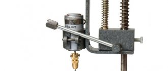
The design of a drilling machine made from a screwdriver consists of the following main elements:
- Base:
- Vertical frame;
- Spindle box;
- Platform (horizontal support);
- Drilling table;
- Fastening a drill (screwdriver) used as an electric motor and spindle;
- Drill (screwdriver);
- Spring-loading mechanism and drill feed handle.
Photo of a do-it-yourself drilling machine
Making a grinder from a grinder
Many may say that the “grinder” is the same as an angle grinder, but there are some subtleties hidden here. It should be borne in mind that the angle grinder has very high speeds and often quite a decent weight. To polish a surface with a grinder, you need to have considerable experience in this matter and use special polishing discs and circles. The grinder has much lower engine speed and weight. To operate a factory grinding machine, no specific experience or skill is required. You can independently make a good grinder from an angle grinder, which is not inferior in its parameters to a factory machine, only by modifying its electrical circuit, by installing the regulator at lower speeds and by using special grinding attachments.
Mini grinder made from improvised means
This device is suitable for those who are engaged in modeling - they often have to cut parts from hard materials. It is impossible to use standard angle grinders in this case: it is necessary to cut very small elements. For this work you need to make a mini grinder. It is made from a small electric motor. It could be from a faulty VCR, printer, or children's toy. Such a device is powered by a cell phone charger, USB input, battery or several batteries.
The most difficult thing is making the cutting element yourself. The disc is made from the thinnest cutting wheel. The diameter is chosen independently, according to the conditions of use.
Sometimes the cutting wheel is made from an ordinary drink cork.
The manufacture of the device begins with processing the handle - attaching the motor to it. A collet clamp is mounted on the axle. Take the prepared circle and secure it with washers on the M6 screw. It turns out to be a kind of nozzle, which is fastened with a collet clamp.
The tool is ready for use. The motorized mechanism can be used without a handle if you need to trim parts inside the model.
You can watch how to make the device in this video:
Anyone wishing to make a device should know that a homemade angle grinder does not meet safety requirements. If there is no urgent need, it is better not to risk your health, and sometimes even your life.
Source: tehnika.expert
Manufacturing algorithm
Considering that home machines will be interchangeable in terms of the type of processing, and the decisive role will be played by the attachment installed in the drill, we will consider two main options for home-made units - horizontal and vertical.
The procedure for assembling a vertical machine is as follows.
- Cut a square base 50 by 50 cm from a piece of metal or wood, with a thickness of 10 to 20 mm.
- Drill a hole in it exactly in the center at a distance of 1-2 cm from the edge for mounting the stand. The diameter of the stand must be at least 5 cm.
- Install the stand, center it using a level and weld it with a welding electrode. If you are making a wooden machine and the stand will be wooden, then firmly fix it with self-tapping screws.
- Using metal clamps, secure the drill to a movable element that will be put on the stand, forming a lowering/raising spindle.
Place the spring on the strut. Its length must be at least 2/3 of the rack. Having placed the drill on the stand, mark the place where the drill will hit when lowering the spindle. According to this place, cut two through hollows in the frame crosswise. A table is installed in the groove on the threaded pin on which the workpiece will be mounted. A nut is screwed onto the pin from the bottom side; it will fix the table in the desired position.
You can also attach the table to the pin from the outside with a nut, recessing it into the surface of the table so that it does not interfere with the placement of workpieces. It is important that after securing with a nut, the length of the outer part of the pin is flush with the top surface of the table.
The assembly algorithm for a horizontal machine looks like this.
- Cut a rectangular frame - dimensions are determined individually.
- At one edge, secure a seat for a drill with a hollow in the upper part corresponding to the size of the tool.
- Secure the drill to it with a clamp.
- Cut a through groove for the pin along the frame, and install two metal corners along the edges along which the pressure sleeve will move.
- The width of the pressure sleeve must exactly match the distance between the guide angles (runners). A threaded pin is screwed into it from below, which will move in the hollow.
- By moving the sleeve close to the drill chuck, determine the place where the special headstock will be installed for fixing the workpieces.
- Attach the headstock to the bushing with a metal cone-shaped pin placed in the center.
- The sleeve is fixed in the desired position (for clamping the workpiece) with a nut screwed onto the pin from below.
In both options, it is necessary to provide special adjustable legs for the frame.
If the bed rests flat on a workbench or table, it will become impossible to adjust and fix the clamping sleeve on a horizontal machine or the workpiece table on a vertical one.
How to make a drill press using a drill
Using an electric drill is probably the easiest option for making a homemade drilling machine, because... in this case, the issue of fixing the drill is resolved (a drill chuck is used), and an electric drive is also provided. The main problem in this case that needs to be solved is the manufacture of a frame and a mechanism for moving the drill in a vertical plane. All work can be divided into several stages that determine the nature of their implementation: preparatory, execution of work and final.
The metal stand for securing the drill is easy to manufacture and convenient to use.
Preparatory stage
During this period of work it is necessary:
- Decide on the materials and components that are available and that can be used to manufacture the machine: wood or metal, spare parts for cars, motorcycles or household devices, electrical wires and switching devices, as well as protective equipment.
- Depending on the selected materials, the necessary tools are prepared. This can be a grinder and a welding machine (inverter), a circular or circular saw, as well as carpentry tools and fasteners.
- A drawing (sketch) of the structure being created is developed, with the main dimensions being: the mounting location of the drill used and the size of the drill movement.
Wood structure is not strong enough, but can be fully used for making printed circuit boards
Execution of work
Having decided on the materials and tools, as well as having prepared them and developed a drawing, you can begin manufacturing. Below are step-by-step instructions for making such equipment using a metal sheet and profile.
| Illustration | Description of action |
| The base (plate) of the machine is made from a metal sheet 10-12 mm thick, on which holes are drilled for its subsequent fastening. A metal profile (stand) with a cross section of 40×40 mm is welded to the plate. | |
| When installing the profile, check that it is strictly in a vertical plane to ensure the correct movement of the drill in the future. | |
| A workpiece is cut out of a metal profile with a cross-section larger than the welded stand, after which the possibility of its movement along this stand is checked. | |
| A cut is made on the workpiece along its entire surface. | |
| After this, a metal structure is made from a profile of a similar cross-section, into which the bicycle sprocket is placed. | |
| A bicycle chain is fixed to the surface of the vertical stand using welding. | |
| The ability of the assembled structure to move along the rack is checked. | |
| A fastener is cut out of a metal pipe with a diameter larger than the chuck of the drill being used, which is welded to the previously assembled structure. | |
| The reliability of the drill is checked. | |
| From a profile of a smaller cross-section, levers are made that serve to drive the movement mechanism, which are mounted on a previously assembled structure. | |
| The functionality of the lifting and lowering mechanism is checked. |
Final stage
At this stage of work, the following activities are performed:
- the assembled metal structure is painted;
- moving units are lubricated;
- For ease of use, a plug socket can be installed on the stove to plug in an electric drill with a connected electric cable that serves to connect it to the network.
Manufacturing option using a car jack
Types of do-it-yourself drilling machines
There are different types of drill presses made at home. They differ in: material of manufacture, structure, size.
And home craftsmen never stop coming up with new designs and selecting sizes for drilling machines. After all, not everyone makes machines according to ready-made drawings.
Here are some of the most popular drill press designs:
Wireless machine made of wood. This design is well suited for portable drilling of large items. Since the operation of the drill in such a machine is provided by the battery, it is necessary to make a special wooden box. The machine drawing is adjusted independently to the dimensions of the built-in drill.
Mini drilling machine. Making such a tool will not take much effort and time. This design is considered the most economical and does not require a large amount of materials. The model is designed depending on the size and shape of the drill; the drill itself can be secured with ordinary rubber bands or cable ties.
Machine made of plastic pipes. This option is good for those who have pipe scraps left after plumbing repairs. In another case, this option is very economical, since PVC pipes are cheaper than metal or wood. It’s not that difficult to make, the main thing is to maintain the proportions and dimensions.
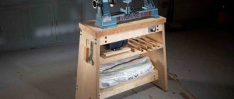
Homemade machines and devices for the home workshop: general information
Each owner of a garage or workshop, depending on his needs, selects the equipment himself. Many of them know how to make homemade machines and devices for garages, so they make do with their own resources when arranging the premises, customizing the technical features of the structures to suit themselves.
So, when creating a metal workbench with your own hands, the drawings and dimensions of the product on them can be adjusted to the parameters of the room and other conditions. Even for a small home workshop, you will need to allocate enough space to accommodate at least the design of a universal folding workbench and a minimum set of tools. The required area for this is at least 3-5 m².
A workshop set up in a specially designated room
Manufacturing of tools storage devices: shelves, racks
In fact, it is very difficult to achieve optimal operating conditions. It is desirable that the size of the room be at least 6.5 m. To equip a workshop, you can make an extension to the house or garage. This solution will be the most profitable in any case.
Before designing a drawing of a folding workbench with your own hands, which has the largest design (therefore its dimensions are taken into account first), it is worth deciding on some points:
- indicate what types of work will be performed in the workshop;
- determine a list of necessary tools and equipment.
By mounting the tool on the wall, you can significantly save useful space in the workshop. Shelves or racks are perfect for this. You can successfully arrange these structures, achieving the most rational distribution of area.
The home workshop should be located so that noise from working tools does not disturb residents
In order to save space, you can get a special device for a circular saw with your own hands, made on the basis of a conventional drill. Such a universal machine can perform several functions at once, combining the following capabilities:
- circular saw;
- grinding machine;
- sharpened;
- mini lathe for wood;
- cutting machine.
The work table can be combined with a vice for a carpentry workbench and equipped with drawers to store small tools.
DIY tool shelves: popular designs
Metal structures are more durable and reliable, while wooden ones are affordable. There are several options for rational storage of tools:
- wall shelves;
- DIY tool racks;
- suspended ceiling shelves;
- Shelves-boards for hanging small tools.
Perforated steel shelf for hanging small tools
Technology for making a shelf for tools with your own hands (shield):
A shield is cut out of a plywood sheet, and the places where the shelves will be installed are marked on it. Using a jigsaw, shelves with side walls are cut out. The length of these sides must match the length of the shield. Shelves for tools are assembled and fixed to the surface of the shield using long self-tapping screws. Hooks are being installed. Holes are made in the shield where dowels are installed. You need to screw special hooks equipped with threads into them. First, you should distribute the entire tool and mark the points where it will hang. Brackets or lugs are installed on the rear wall of the structure.
All that remains is to fix the shield shelf on the wall. To prevent the lugs from sliding off the anchors, it is recommended to fix them with special washers.
Diagram of the device with installation dimensions of the tool rack in the workshop
Original idea
This design is very versatile, since its basic part (base and spindle box) is the working part of several other devices described in the following articles:
- DIY wood lathe. Description, drawing, video.
- Do-it-yourself thicknesser machine: drawings, photos and videos.
- Homemade grinding machine from a drill (screwdriver). Description, drawings, video.
These articles contain photos and videos of do-it-yourself machines.
| Turning | Thicknesser | Grinding |
Thus, part of the structure of the described machine can be used for the manufacture and subsequent assembly of three more additional devices. If necessary, having all the components, you can assemble the devices you need at the moment at your own discretion.
Woodworking Machine
The woodworking equipment market offers an extensive line of wood lathes. Each consumer makes his choice taking into account his interests, but the main criterion is the drive power. For a home workshop where turning work is performed sporadically, a simple tabletop machine with an electric motor power of 1 kilowatt and a spindle speed of 3500 rpm is suitable.
https://youtube.com/watch?v=xs8KOp1HoFI
The main components and mechanisms of a wood lathe correspond to the classic structure of a lathe, which processes workpieces by rotation. Three main mechanisms:
- drive - electric motor, single-phase or three-phase;
- transmission - a set of devices that transmit the rotation of the motor shaft to the spindle head;
- the executive is the support.
Four main nodes:
- bed - the body on which the mechanisms are fixed;
- front spindle headstock - for attaching a faceplate or lathe chuck;
- rear fixing headstock - for installing a rotating center or drill chuck.
Popular articles Cat pillow
Design feature
You can assemble a wood lathe with your own hands from available materials. The design is simple and does not require much time to manufacture. The main part of the machine is a bed made of a channel, in which a groove is cut along the central center line with a grinder for fixing the tool rest and tailstock. The fixation principle is an eccentric mechanism.
The tailstock design is standard. The quill has a hole for Morse taper No. 2 to set the center of rotation. The drill chuck shank matches the quill hole. It is recommended to use a factory made tailstock.
Under the quill, machine a hollow cylinder with a blank end wall, in which a thread is cut for the flywheel screw. The moving part of the quill is a cylinder with a conical hole and a keyway along its entire length. The moving part moves with the help of a flywheel screw along a key welded in the headstock body.
The tool rest is classic, has an adjustment function with fixation to the diameter of the workpiece being processed, the base of the tool rest moves across and along the bed. It is fixed with an eccentric with a handle. The upper part is a regular corner.
The headstock has two angular contact bearings. The spindle shaft has an M14 thread, step two. This is a thread that is used on grinders and grinders. Thanks to this, all the attachments used by the grinder can be attached to the spindle.
DIY spindle head
The quality of the entire structure depends on the accuracy of the headstock manufacturing
Therefore, special attention must be paid to this node. Craftsmen recommend making the headstock of a lathe with your own hands
To do this, you need to machine a cylindrical body with a wall thickness of 10 mm. To attach it to the frame, you need to make a special stand. A section of channel is suitable for this. The channel end is welded to a corner made of sheet steel 10 mm thick. The headstock body is attached to the resulting stand.
To make a wood lathe with your own hands, drawings and dimensions do not matter, since everyone makes the design individually, taking into account their capabilities. Sectional view of a cylindrical body:
- outer diameter 56 millimeters;
- wall thickness 10 millimeters;
- length 180 millimeters;
- mounting sockets for bearings with a diameter of 24 millimeters;
- shaft with a diameter of 30 millimeters.
Simple accessories make the machine universal and increase the list of operations. For example, by installing a sanding drum with sandpaper in the chuck, you can sharpen the tool. The device for turning on a copy machine looks like this:
- copier;
- a pipe installed along the frame, acting as a slide;
- circular electric saw that acts as a wood cutter.
The milling attachment will replace the milling machine. Arbor with disc cutter
is clamped into the chuck. Instead of a tool rest, a work table with a stop ruler is installed. You can mill platbands, baseboards, and blanks for frames.
Enthusiasts and lovers of making homemade items are constantly coming up with mechanisms that make manual labor easier. Such people always have an answer to the question of how to make a woodworking machine.
Characteristics that a belt for a sanding unit must meet
Selecting an abrasive strip is an important step when assembling a mini-grinder with your own hands. First of all, you need to decide on the length of the tape and its width. The geometric parameters of the strip are influenced by two main factors:
- grinder dimensions;
- purpose of the unit.
Fabric base withstands surface tension better
Endless abrasive strips are also classified into grit types. The length of the sanding strips can be different (from 610 to 1830 mm). Such tapes have a width of 50 or 100 mm. The first option is most often found in units assembled by hand at home.
A high-quality abrasive strip must have an elastic fabric base
When choosing the right tool, you also need to pay attention to how many revolutions the strip can withstand. It is recommended to purchase products that can operate at 1500 rpm
This option is best suited for making a belt grinder with your own hands. The drawing drawn up earlier must contain information about the dimensions of the abrasive strip and its other characteristics.
A good tape must have high abrasive resistance. The wear resistance of the tape depends on this indicator. For homemade machines, it is recommended to use belts whose length is no more than 123 cm. The abrasive strip must not only be resistant to wear, but also have good resistance to high temperatures generated during friction against the workpiece during operation.
It is worth noting that short-length tapes are much more susceptible to wear than longer products.
Experts advise paying attention to pictures depicting finished products. Photos of the machines allow us to answer the question of how to make a grinder with your own hands
The design of the device can be significantly simplified if ready-made elements purchased separately are used in its assembly.
The speed and quality of product processing depends on the choice of tape.
And finally, special attention must be paid to the place where the abrasive tape is glued. The junction of the two ends of the strip should be as neat as possible, without any defects or protrusions
How to glue the tape for the sanding unit yourself
Belt grinders contain a spring, which performs a very important function: it tensions the belt that has sagged due to wear. The belt is changed several times even when processing a small workpiece. This should be remembered.
When assembling a grinder with your own hands from plywood or metal, you can make an abrasive strip yourself. Gluing such tape is a complex undertaking that does not tolerate mistakes. There is a lot of advice on the Internet on how to properly glue tape, but many of them are incorrect.
The gluing process is as follows. First you need to select a fabric-based sanding material. Then you should prepare both ends of the abrasive strip. To do this, they are cleaned. The seam on the strip is made exclusively using the butt method. Experts definitely recommend reinforcing the glued tape from the inside with a thick strip of fabric, which is fixed with a special adhesive composition.
Gluing tape is a complex process that does not tolerate mistakes.
In order to connect the ends of the abrasive strip, you need to purchase a special adhesive composition. The best option is to use elastic glue. There is no point in saving money, since cheap products, as a rule, are not of good quality.
Before gluing, it is necessary to prepare a strip for sanding tape. A do-it-yourself grinder (from scrap materials) needs a reliable abrasive strip, which is difficult to do at home. The process is carried out using a glue stick, which is installed on hot-melt guns. First, the composition is heated. To do this, you can use a regular hairdryer, which is found in every home.
What can be made from an old screwdriver: 19 cool ideas
At home, you can make household electrical appliances or equipment for various purposes from an old screwdriver. This will require a little imagination and additional tools. Homemade devices and tools will cost much less than their factory-made counterparts, and their service life will be several orders of magnitude longer.
Generator
Cordless screwdriver models are perfect for creating a homemade generator. By rotating its handle, the device will be able to supply electrical energy. Such a generator can be used during a camping trip or when there is a power outage in a country house. A homemade generator can be used to recharge batteries (6-12V).
A screwdriver with an operating voltage of 18 V or more is suitable for the job. Craftsmen advise following the following sequence of actions:
- Disassemble the screwdriver body.
- Unsolder its electrical board.
- In place of the battery, install a diode bridge that is suitable in terms of technical parameters and characteristics.
- Make an easy-to-use handle by securing it in the screwdriver chuck.
Once these simple modifications are completed, all that remains is to assemble the body. The homemade generator is ready to work.
Bulgarian
If you don’t have a grinder, you can replace it with a homemade grinder made from an old screwdriver. To do this, use a nozzle or adapter equipped with a gearbox, which can be purchased ready-made. The possibility of making such devices with your own hands cannot be ruled out. For this, studs, nuts and washers are useful, the diameter of which is similar to the diameter of the screwdriver chuck.
Trimmer or lawn mower
Equipment for mowing grass on the site is not cheap. If necessary, it can be made at home using an old screwdriver. In addition, you need to prepare the following materials:
- plastic pipe up to 2 m long;
- fasteners;
- stub;
- motor from an electric screwdriver with a power of 12 V and its battery;
- the wire;
- adapter for pipe (40-50 mm);
- button;
- plastic bucket;
- crocodiles (clips);
- blade of a stationery knife.
The workflow for creating a trimmer or lawn mower consists of several stages. To obtain the desired result, you need to follow their sequence:
- Disassemble the screwdriver body by removing its motor.
- Mark the mounting locations on the plug and drill them out with a drill.
- Secure the motor to the plug by screwing it with 2-3 screws.
- Solder the leads for the motor.
- Install the motor into the seat. Pass the wires coming from it through a plastic pipe.
- Mark on the pipe the place where the power button will be located using a marker. Drill a hole.
- Connect the wires to the button. To quickly turn on the device using a battery, you can also solder crocodiles.
- Make a battery holder from an adapter.
- Install the storage tank by connecting it to the adapter on the pipe.
- Make knives for future equipment from the blades of a stationery knife.
- Connect the motor shaft and the attachment using a terminal clamp.
- The protective casing can be made from a plastic bucket, connecting it to the lower end of the pipe.
This homemade device can be used for mowing young vegetation.
Engraver
Both cordless and electric models of screwdrivers are equally suitable for making a drill. To remake it, it is enough to purchase a special adapter and make a bit whose diameter fits the adapter.
Garden shredder
Using an electric screwdriver, you can make a shredder of garden branches (with a diameter of no more than 1 cm) or grass. The power of the screwdriver should not exceed 0.5 kW.
When working, it is recommended to follow the following sequence of operations:
- Prepare a container that will contain the grass or branches to be chopped. This could be a boiler or a large bucket.
- In the central part of the bottom of the container, drill a hole into which the shaft will be inserted to fix the cutting elements of the chopper.
- To install the container and convenient work, you can install it on the edge of the table or make a frame for this from wooden slats.
- Install the cutting elements on the shaft, securing them with bolts. For this purpose, hacksaw blades installed with the sharpening point downwards are better suited.
- Install a screwdriver with installed knives at the bottom of the frame.
- Solder the button to turn on the unit.
- Cut a hole (10x20 cm) in the lower part of the container wall. Insert a metal or plastic sleeve into it, through which the crushed raw materials will be discharged.
The device is ready for use. To ensure efficient operation, it is recommended to first break the branches into small pieces.
Wind generator
An old cordless screwdriver is suitable for creating a simple model of a wind generator that will look like a weather vane. It is necessary to disassemble the tool and disconnect its contacts, dismantle the mechanical elements.
Insert the electric motor shaft into the chuck, clamping it securely. Attach a metal plate no more than 1 mm thick to the gearbox with bolts, which will subsequently serve as the basis for mounting the wind generator blades.
A plastic pipe cut lengthwise into 2 parts is ideal for making blades. Place a clamp on the shaft located between the gear and the chuck. The motor and cartridge are securely attached to the base made of plywood.
General information
Certain types of homemade grinding machines have a fairly simple design, and you can assemble them as needed. The rest are very similar to industrial designs and are an unusual example of the beauty of home engineering.
Old electric motors from household appliances, as well as driven electric tools, are most often used as drives in such devices. Very often with conventional grinding. The drive part of the machines is made on the basis of a grinder or an electric drill. We propose to consider how to make a belt sander from a drill with your own hands.
The basic structure of a grinding machine
Without thorough knowledge of the design of grinding machines, it is impossible to assemble a high-quality device with your own hands. Before moving on to the structure, let's get acquainted with the most common types of grinders:
- Corner. Simply put, Bulgarian. Consumables are discs. Grinding wheels are designed for surface grinding. Pressure adjustment is carried out manually.
- Tape. Surface treatment is carried out with a sanding belt. Suitable for working on flat surfaces only.
- Delta sander. For processing products with a curved structure.
- Vibrating. Ideal for finishing smooth surfaces.
In addition to the above, there are several more devices that are less common:
- straight;
- polishing;
- eccentric.
Regardless of whether the device is factory-made or self-assembled, the main design elements are:
- Drive unit. The performance of the device depends on its power. Do-it-yourself devices use an electric drive, but there are pneumatic homemade ones powered by a compressor.
- Gearbox. Transmits torque from the drive to the working tool. The basic part of the gearbox is the spindle.
The gearbox is an integral part of tools such as an angle grinder or a drill. Some models, especially those assembled with your own hands, can do without it.
- Working platform. An abrasive material is attached to it. For this you can use circles, tapes, disks.
- Frame. Protects the structure from mechanical damage and dust, which is why many factory models are equipped with dust collection systems. The materials used to make a device with your own hands, as a rule, are not able to compete with high-quality polymers that are used in the production of professional tools.
- Control system. Includes turning off the power, as well as adjusting the abrasive speed.
Options for homemade designs
Making a grinding machine with your own hands is not difficult. The main thing is that it corresponds to the types of work that the master plans to perform. From an economic point of view, it is better to take components that are on hand. If you have to buy the components of the device, then the budget of a home-made device will be comparable to a factory model. All other things being equal, it is better to give preference to an industrial tool, because its quality is disproportionately higher.
Let's look at a few handmade devices. Perhaps one of them will suit you.
Do-it-yourself grinder from an angle grinder
As the name suggests, the grinder is designed for grinding. Cleaning discs successfully cope with rough work: removing old paint, removing metal deposits or traces of corrosion. For finer cleaning, special attachments made from sanding sheets of various grain sizes are sold.
Models for domestic use operate in one mode, and the number of revolutions reaches 15 thousand per minute with an average of 11 thousand. This speed is great for sawing materials, but it is too high for sanding work.
The grinder's motor has excess power. For polishing, 300–400 W will be enough.
A grinder made from an angle grinder will have more weight compared to a factory tool, but it is possible to adapt a homemade one for yourself, which will increase comfort when grinding.
For an angle grinder, you can make a simple attachment that will turn the device into a miniature belt grinder. In this case, work is carried out without a protective casing.
If you do not want to use devices, you can adjust the number of engine revolutions. Independent modernization of the circuit will require specialized knowledge in electrical engineering.
On professional devices, you can set the number of revolutions manually, however, their cost starts from $200.
Making a grinder from a drill
You can use a drill to build a productive belt sander with your own hands. In this case, the tool acts as a drive. The design itself is simple and does not require significant investment. To make it yourself you will need the following materials:
- metal rods with and without threads;
- profile pipe;
- plywood;
- steel sheet;
- bearings;
- hardware;
- wood glue.
You should make sure that you have metalworking tools, an inverter and devices for sawing metal.
Stages of work:
Manufacturing of pulleys. The driving and driven pulleys are designed to transmit torque from the drill to the grinder. They are made from plywood.
By changing the diameter you can obtain the desired torque. One pulley consists of several round timbers, which are connected using wood glue. In the center it is necessary to drill holes for steel rods. After the glue has dried, the workpieces are modified by making a groove that must correspond to the width of the drive belt.
Manufacturing of drive and driven shafts. They are also made from plywood, similar to pulleys. More round logs should be prepared for them.
Assembling the lower part. To do this you will need a profile pipe. First of all, it is necessary to make mountings for the bearings and connect them. This is the base for the working shaft.
Making the top part. The tension mechanism will be attached to it.
We make the thrust part from a steel sheet.
Drive installation
Please note: for normal work it is better to take a powerful drill. Finishing work. All that remains is to install the pulleys, tension the drive belt and assemble the protection
After this, the hand-assembled device needs to be coated with paint.
For small and precise work, it is better to purchase compact drum or plate type attachments, depending on the type of work.
Homemade grinder from a computer hard drive
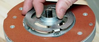
From an old hard drive you can assemble a small grinding device, the main advantage of which will be the complete absence of investments, with the exception of the cost of abrasive wheels. The DIY manufacturing process is as follows:
- Open the case and remove all elements located next to the magnetic disk.
- According to the size of the upper part of the drive, cut out a circle of sandpaper of the desired grit.
- Using double-sided tape, secure the paper to the surface of the disk.
- We make a casing that protects from dust or abrasive grain.
- To start the design, the hard drive must be connected to the computer's power supply.
Instructions for creating a stationary circular saw with your own hands
Creating a table for a hand-held circular saw with your own hands is the most important stage in creating the machine, since this structure will house the main parts of the equipment in the form of:
- power unit;
- control block;
- cutting component;
- other components.
The support bed on the hand tool table doubles as a guide for your DIY circular saw. It controls the direction in which the cut is made and fixes the workpiece.
Construction of a table for a hand-held circular saw is the most important stage in creating a machine
The sawmill is a modification of the circular saw. The only difference is that the disk is located at the bottom. The design of the table for a circular saw with your own hands is assigned the function of a bed. The power unit, block, fixing disk and control system are also installed here.
At the design stage for DIY circular saw drawings, you should take into account some factors:
The depth to which the material will be cut depends on the geometry of the disk. The power level of the electric motor - a specific indicator of 800 W will be sufficient. Control system installation area - the control should be located as far as possible from the disk. Rotational speed - the minimum acceptable value is 1600 rpm, otherwise color change will occur during the cutting process.
Diagram of a stationary circular saw
How to make a circular saw from a grinder with your own hands
First, the tabletop is made from sheet material. Markings are applied to it in accordance with the dimensions of the instrument. Using these markings, cutouts are made to install the saw.
Next is done:
Installing a rip fence for a circular saw with your own hands, made from a wooden strip. The element is fixed to the tabletop. Groove for stop – these elements are formed on the tabletop using the milling method. Installation of a ruler for measurements - the installation area is located at the leading edge of the cutting element. The ruler will be used to control the dimensional parameters of the workpieces. Installation of clamps is an additional component for fixing the workpiece.
For a DIY circular saw machine you will need legs. They are mounted taking into account the dimensions of the tabletop made of wooden beams with a section of 4x4 cm. The use of steel corners is allowed. To provide additional stability, stiffeners should be installed between the supports. A control unit is placed next to the workplace. You should not refuse to install RCDs and devices that protect the engine from overloads.
Variant of a circular saw from a drill. Layout diagram: 1 - drive (electric drill); 2 — work table (duralumin, sheet s5); 3 - circular saw; 4 — rack (St3, strip 20?5, 4 pcs.); 5 — support holder of the mandrel shaft; 6 — mandrel; 7-electric drill holder; 8 — base plate (furniture chipboard, s30)
Multifunctional device - miter box
By making the work table for your angle grinder more rotatable, you will get a multifunctional device - a miter box.
This device allows you to work not only with wood, but also to cut profiles, baseboards, baguettes and other workpieces at a certain angle. To make such a part, you need to install the working disk on the grinder and fix the table at an angle of 45 degrees. It is worth noting that such a unit is considered a real salvation for those who need to cut a large number of window casings, skirting boards and glazing beads. A miter box in combination with an angle grinder allows you to work even with paving slabs in a diagonal direction. And this, in turn, helps to diversify styling options.
Design
There is nothing particularly complicated in the design of a belt grinder. The device consists of a motor, drive and guide rollers. A sanding or roughing belt of the required grain size is passed through them.
When the engine is turned on, the drive roller mounted on its shaft begins to rotate, and through the tensioned working belt, the rotation is transmitted to the guide rollers. By pressing the part to be processed in the working area against the belt, the operator performs the required operation, changing the position of the workpiece relative to the surface of the belt if necessary.
By adjusting the distance between the guide rollers, it is possible to process surfaces with defects of different depths. During prolonged use, the sanding belt may not stretch much. To compensate for possible slack, a tension mechanism is provided in the design on one of the rollers. Typically, such a function is assigned to a roller located at the same distance between the leader and the slave.
The grinding machine is supplied with a support table, which also serves as a surface for fixing the workpiece. As a rule, such a table should be able to rotate 90 degrees about one axis. In this case, it is possible to process two perpendicularly located planes without reinstalling the part on the support table.
Of course, a grinder control panel is required! For safety reasons, it is recommended to mount it on the machine frame in close proximity to the operator’s working area. Portable machines are equipped with a stand made of durable steel with mounting holes on the base, allowing you to fix the unit on a wooden surface.
If you look at the design details, you can immediately notice some visual instability of the assembled grinding device. The overhang of the side dimensions of the installed rollers significantly exceeds the supporting surface on the base. In addition, the absence of a support table makes it difficult to effectively process relatively large surfaces, and holding the part in a canopy is inconvenient and quite dangerous.
An increased length of the working belt leads to additional losses due to friction. It is necessary to use a higher power power unit in the drive, and this increases energy costs. The tension unit is simple and functional. Adjusting the tension is a matter of seconds. The machine comes with replaceable sanding attachments, which can be used for sanding even on internal surfaces. Despite this, the cost is 100 thousand rubles. makes me think.
We understand the design of turning equipment
In the design of any lathe, several main components can be distinguished, which will also form the basis of our homemade home equipment.
Drawings of the main components of a homemade lathe from a drill (click to enlarge)
bed
This is the basis of the device, responsible for the reliable fastening of its component elements and their precise location relative to each other. This element of turning equipment also ensures its stability. Stationary units have a massive frame, which is located on special legs. For tabletop machines that can be easily transported to any convenient location, the frame is made in a lighter weight.
Headstock
This element of turning equipment is responsible for fixing and rotating the workpiece being processed, which is secured in a chuck installed in the spindle assembly. On small turning units, including homemade ones, the headstock can move along the bed guides. This is required in order to perform alignment and adjust the relative position of the structural elements of the device. During processing, this machine unit is securely fixed. On stationary models of turning units, this unit is stationary; it is made integral with the bed.
Tailstock
This is a movable unit of the machine, responsible for fixing and pressing the workpiece to the chuck when processing it in the centers. Moving freely along the bed guides, the tailstock allows you to install and process parts of various lengths on a lathe. A very important requirement for this structural element is its ideal alignment with the spindle assembly.
Caliper
On mini-machines, including self-made units based on a drill, the role of this unit is played by a tool rest, which must be able to move along the guides of the bed and be securely fixed in the working position. The rest on small devices acts as a stop for the cutters, and the cutting tool itself is pressed against the supporting surface and held there manually.
General view of the machine Drill fastening Tailstock Fastening the support platform View assembled with the workpiece using an angle stop
On any lathe, its front and tailstocks have one degree of freedom and can only move along the axis of rotation, and the support (or tool rest) can move in both longitudinal and transverse directions. The ability to move the tool rest in the transverse direction is also important in order to minimize the lever arm created by the cutter. If the distance from the end of the supporting surface of the tool rest to the workpiece being processed is large, it will be very difficult to hold the turning tool. The tool may simply be torn out of the operator's hands, resulting in serious injury.
Safety precautions when working on a sanding grinder
Like any other work on any other machines, grinding on a homemade belt sanding machine is subject to fairly strict safety rules that must be strictly adhered to.
The principle of operation of the grinder.
These rules are as follows:
- It is strictly forbidden to touch anything that moves with your hands while the machine and working surface are operating.
- Wear safety glasses while working to protect against hot abrasive particles.
- Carefully check that the connections and fastenings of all moving parts of the grinder are tight.
- Monitor the condition of the braiding of electrical wires.
- A protective casing is a must, even though it slightly narrows the viewing angle.
Making a grinder from a grinder
Many may say that the “grinder” is the same as an angle grinder, but there are some subtleties hidden here. It should be borne in mind that the angle grinder has very high speeds and often quite a decent weight. To polish a surface with a grinder, you need to have considerable experience in this matter and use special polishing discs and circles. The grinder has much lower engine speed and weight. To operate a factory grinding machine, no specific experience or skill is required.
You can independently make a good grinder from an angle grinder, which is not inferior in its parameters to a factory machine, only by modifying its electrical circuit, by installing the regulator at lower speeds and by using special grinding attachments.
How to make a grinder from a drill
There are various devices for manual and mechanized grinding. All of them can be divided into two main types.
- Tools that directly perform the processing of the part are hand-held devices, which include sanding blocks (pads, whetstones) and grinding attachments for a drill
or grinder, which are all kinds of support plates and drums. - Devices that ensure the required position of the grinding tool relative to the part - guides, supporting surfaces, etc.
A separate type includes devices for dust removal, which, due to the abundance and harmfulness of grinding dust, should also not be neglected.