A drilling machine for printed circuit boards belongs to the category of mini-equipment for special purposes. If desired, you can make such a machine yourself using available components. Any specialist will confirm that it is difficult to do without the use of such a device in the production of electrical products, the circuit elements of which are mounted on special printed circuit boards.
Simple mini PCB machine
General information about drilling machines
Any drilling machine is necessary in order to ensure the ability to efficiently and accurately process parts made from various materials. Where high precision processing is required (and this also applies to the process of drilling holes), manual labor must be eliminated as much as possible from the technological process. Similar problems are solved by any drilling machine, including homemade ones. It is practically impossible to do without machine equipment when processing hard materials, for drilling holes in which the efforts of the operator himself may not be enough.
Design of a benchtop belt driven drill press (click to enlarge)
Any drilling machine is a structure assembled from many components that are securely and accurately fixed relative to each other on a supporting element. Some of these nodes are rigidly fixed to the supporting structure, and some can move and be fixed in one or more spatial positions.
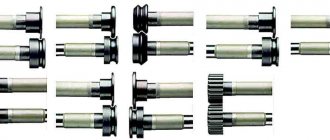
An example of motors used in the manufacture of a homemade mini drilling machine
The basic functions of any drilling machine, through which the processing process is ensured, is the rotation and movement in the vertical direction of the cutting tool - the drill. On many modern models of such machines, the working head with the cutting tool can also move in a horizontal plane, which allows this equipment to be used for drilling several holes without moving the part. In addition, automation systems are being actively introduced into modern drilling machines, which significantly increases their productivity and improves processing accuracy.
Below, as an example, are presented several design options for homemade drilling machines for circuit boards. Any of these diagrams can serve as a model for your machine.
Parts for assembly
- Engine with chuck and collet. On the one hand, a jaw chuck is very convenient, but on the other hand, it is much more massive than a collet clamp, that is, it is often subject to beats and very often they have to be additionally balanced.
- Plywood parts. A link to files for laser cutting in dwg format (prepared in NanoCAD) can be downloaded at the end of the article. You just need to find a company that deals with laser cutting of materials and give them the downloaded file. I would like to note separately that the thickness of the plywood may vary from case to case. I come across sheets that are a little thinner than 5mm, so I made the grooves 4.8mm each.
- 3D printed parts. A link to files for printing parts in stl format can also be found at the end of the article
- Polished shafts with a diameter of 8mm and a length of 75mm - 2 pcs. Here is a link to the seller with the lowest price for 1m that I saw
- Linear bearings 8mm LM8UU - 2 pcs.
- Microswitch KMSW-14
- Screw M2x16 - 2 pcs.
- Screw M3x40 h/w – 5 pcs.
- Screw M3x35 slot - 1 pc.
- Screw M3x30 h/w – 8 pcs.
- Screw M3x30 h/w with countersunk head - 1 pc.
- Screw M3x20 h/w - 2 pcs.
- Screw M3x14 h/w - 11pcs
- Screw M4x60 slot - 1 pc.
- Bolt M8x80 - 1 piece
- Nut M2 - 2 pcs.
- M3 square nut – 11pcs
- Nut M3 – 13pcs
- M3 nut with nylon ring - 1 pc.
- Nut M4 - 2 pcs.
- M4 square nut – 1 piece
- M8 nut – 1 piece
- Washer M2 - 4 pcs
- Washer M3 – 10pcs
- M3 washer enlarged - 26 pcs.
- M3 locking washer – 17 pcs.
- M4 washer - 2 pcs.
- M8 washer - 2 pcs.
- M8 locking washer – 1 piece
- Set of installation wires
- Heat shrink tube set
- Clamps 2.5 x 50mm - 6 pcs
Features of equipment for drilling holes in printed circuit boards
A machine for drilling printed circuit boards is one of the types of drilling equipment, which, given the very small size of the parts processed on it, belongs to the category of mini-devices.
Any radio amateur knows that a printed circuit board is the base on which the components of an electronic or electrical circuit are mounted. Such boards are made from sheet dielectric materials, and their dimensions directly depend on how many circuit elements need to be placed on them. Any printed circuit board, regardless of its size, simultaneously solves two problems: accurate and reliable positioning of circuit elements relative to each other and ensuring the passage of electrical signals between such elements.
Depending on the purpose and characteristics of the device for which the printed circuit board is created, it can accommodate either a small or a huge number of circuit elements. To fix each of them in the board, you need to drill holes. Very high demands are placed on the accuracy of the location of such holes relative to each other, since it is this factor that determines whether the elements of the circuit will be positioned correctly and whether it will be able to work at all after assembly.
Drilling holes in foil getinaks on a homemade machine
The difficulty of processing printed circuit boards also lies in the fact that the majority of modern electronic components are miniature in size, therefore the holes for their placement must have a small diameter. To form such holes, a miniature tool (in some cases even micro) is used. It is clear that it is not possible to work with such a tool using a conventional drill.
All of the above factors led to the creation of special machines for forming holes in printed circuit boards. These devices have a simple design, but can significantly increase the productivity of this process, as well as achieve high processing accuracy. Using a mini-drilling machine, which is easy to make with your own hands, you can quickly and accurately drill holes in printed circuit boards intended for assembling various electronic and electrical products.
Drilling machine from an old microscope
How does a machine for drilling holes in printed circuit boards work?
The machine for forming holes in printed circuit boards differs from classic drilling equipment in its miniature size and some features of its design. The dimensions of such machines (including homemade ones, if the components for their manufacture are correctly selected and their design is optimized) rarely exceed 30 cm. Naturally, their weight is insignificant - up to 5 kg.
Design of a homemade drilling machine
If you are going to make a mini drilling machine with your own hands, you need to select the following components:
- supporting frame;
- stabilizing frame;
- a bar that will ensure movement of the working head;
- shock absorbing device;
- handle for controlling the movement of the working head;
- device for mounting an electric motor;
- the electric motor itself;
- power unit;
- collet and adapters.
Drawings of machine parts (click to enlarge)
Machine console drawing
Let's figure out what all these components are for and how to assemble a homemade mini-machine from them.
Structural elements of a mini drilling machine
Do-it-yourself mini-drilling machines can differ significantly from each other: it all depends on what components and materials were used for their manufacture. However, both factory-made and home-made models of such equipment work on the same principle and are designed to perform similar functions.
It will be easier to make the machine if you take a slide from a computer drive for the drilling head
The supporting element of the design of a drilling machine for printed circuit boards is the base frame, which also ensures the stability of the equipment during the drilling process. Based on the purpose of this structural element, it is advisable to make the frame from a metal frame, the weight of which should significantly exceed the total mass of all other equipment components. If you neglect this requirement, you will not be able to ensure the stability of your homemade machine, which means you will not achieve the required drilling accuracy.
The role of the element on which the drilling head is mounted is performed by a transitional stabilizing frame. It is best made from a metal strip or corners.
Drive carriage with attached homemade corner for the engine
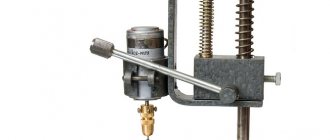
The bar and shock-absorbing device are designed to ensure vertical movement of the drilling head and its spring-loading. Any structure can be used as such a bar (it is better to fix it with a shock absorber) (the only important thing is that it performs the functions assigned to it). In this case, a powerful hydraulic shock absorber can come in handy. If you don’t have such a shock absorber, you can make the bar yourself or use spring structures removed from old office furniture.
The vertical movement of the drilling head is controlled using a special handle, one end of which is connected to the body of the mini-drilling machine, its shock absorber or stabilizing frame.
Lever attachment
The engine mount is mounted on a stabilizing frame. The design of such a device, which can be a wooden block, a clamp, etc., will depend on the configuration and design features of the remaining components of the drilling machine for printed circuit boards. The use of such a mount is determined not only by the need for its reliable fixation, but also by the fact that you must bring the electric motor shaft to the required distance from the movement bar.
Choosing an electric motor that can be equipped with a mini-drilling machine that you assemble yourself should not cause any problems. As such a drive unit, you can use electric motors from a compact drill, cassette recorder, computer disk drive, printer and other devices that you no longer use.
Hair dryer motor
Depending on what kind of electric motor you found, clamping mechanisms for fixing drills are selected. The most convenient and versatile of these mechanisms are the chucks from a compact drill. If a suitable cartridge cannot be found, you can also use a collet mechanism. Select the parameters of the clamping device so that it can hold very small drills (or even micro-sized drills). To connect the clamping device to the motor shaft, it is necessary to use adapters, the dimensions and design of which will be determined by the type of electric motor selected.
Miniature collet chuck
Depending on which electric motor you installed on your mini-drilling machine, you need to select a power supply. When making this choice, you should pay attention to the fact that the characteristics of the power supply fully correspond to the voltage and current parameters for which the electric motor is designed.
Diagram of automatic speed control depending on the load for a 12 V engine (click to enlarge)
Description of design
The design is based on a fairly powerful 12-volt motor from China.
Included with the engine, they also sell a cartridge, a wrench and a dozen drills of different diameters. Most hams simply buy these motors and drill the boards while holding the tool in their hands. I decided to go further and, based on it, make a full-fledged machine for similar engines with open drawings for independent production.
To move the motor linearly, I decided to use 8mm diameter polished shafts and linear bearings. This makes it possible to minimize backlash in the most critical place. These rollers can be found in old printers or purchased. Linear bearings are also widely used and available in 3D printers.
The main frame is made of 5mm thick plywood. I chose plywood because it is very cheap. Both the material and the cutting itself. On the other hand, nothing prevents (if possible) from simply cutting out all the same parts from steel or plexiglass. Some small parts with complex shapes are 3D printed.
To lift the engine to its original position, two ordinary rubber bands were used. In the upper position, the motor switches itself off using a microswitch.
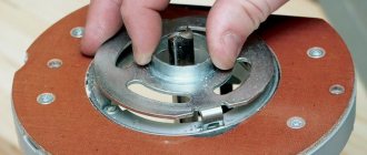
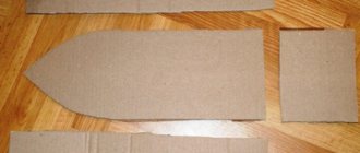
On the reverse side I provided a place to store the key and a small case for drills. The grooves in it have different depths, which makes it convenient to store drills with different diameters.
But it’s easier to see all this once on video:
There is a slight inaccuracy on it. At that moment I came across a defective engine. In fact, from 12V they consume 0.2-0.3A at idle, and not two, as they say in the video.
The procedure for assembling a homemade device
As practice shows, it is most convenient to assemble a homemade machine for drilling holes in printed circuit boards in a certain sequence. You must act in accordance with the following algorithm.
- The frame is installed, and legs are attached to its underside, if they are provided for in the design.
- A movement bar and a holder frame on which the drilling head will be mounted are attached to the assembled frame.
- The holder frame is connected to a shock absorber, which is also fixed to the equipment frame.
- A handle for controlling the movement of the drilling head is installed, connected to a shock absorber or holder frame.
- An electric motor is mounted, the position of which is carefully adjusted.
- A collet or a universal drill chuck is attached to the shaft of the drive motor using adapters.
- A power supply connected to the electric motor via electrical wires is being installed.
- A drill is installed in the chuck and securely fixed in it.
- The assembled homemade machine is tested by trying to drill a hole in a dielectric sheet with its help.
To ensure that your homemade mini-drilling machine can always be disassembled and modified, it is best to use bolts and nuts to connect its structural elements.
If you want to make your own mini-equipment for making holes in printed circuit boards, you can always use the drawings and advice of those who already own such a machine and are actively working on it in their home workshop.
Assembly
The whole process is shown in detail in the video:
If you follow exactly this sequence of actions, then assembling the machine will be very simple.
This is what a complete set of all components for assembly looks like
In addition to them, assembly will require a simple hand tool. Screwdrivers, hex keys, pliers, wire cutters, etc.
Before starting to assemble the machine, it is advisable to process the printed parts. Remove possible sagging, supports, and also go through all holes with a drill of the appropriate diameter. Plywood parts along the cut line may become stained with smoke. They can also be sanded with sandpaper.
Once all the parts are prepared, it's easier to start by installing the linear bearings. They creep inside the printed parts and are screwed to the side walls:
Next, the handle with gear is installed. The shaft is inserted into a large hole, the base of the handle is installed on it and the whole thing is tightened with an 8mm bolt. The handle itself is an M4 screw:
Now you can assemble the plywood base. First, the side walls are installed on the base, and then the vertical wall is inserted. There is also an additional printed piece at the top that defines the width at the top. When driving screws into plywood, do not use too much force.
It is necessary to make a countersink in the table on the front hole so that the head screw does not interfere with drilling the board. A printed fastener is also installed at the end.
Now you can begin assembling the engine block. It is pressed with two parts and four screws to the movable base. When installing it, you must ensure that the ventilation holes remain open. It is secured to the base using clamps. First, the shaft is threaded into the bearing, and then clamps are snapped onto it. Also install an M3x35 screw, which in the future will press the microswitch.
The microswitch is installed on the slot with a button towards the engine. Its position can be calibrated later.
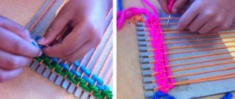
The rubber bands are placed on the bottom of the engine and threaded through to the “horns”. Their tension must be adjusted so that the engine rises to the very end.
Now you can solder all the wires. There are holes on the engine block and next to the microswitch for clamps to secure the wire. This wire can also be routed inside the machine and brought out from the back. Make sure you solder the wires on the microswitch to the normally closed contacts.
All that remains is to install the pencil case for the drills. The top cover must be clamped firmly, and the bottom cover must be tightened very loosely, using a nut with a nylon insert for this.
This completes the assembly!