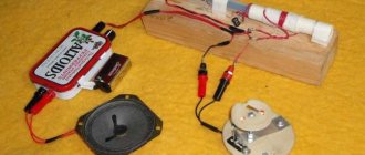
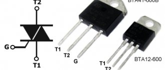
The simplest radio receivers are not suitable for catching the FM range, frequency modulation. Common people say: this is where the name comes from. In English we interpret the letter FM as frequency modulation. A clearly expressed meaning is important for readers to understand: the simplest radio receiver, assembled with your own hands from rubbish, will not accept FM. The question of necessity arises: the cell phone picks up the broadcast. Electronic equipment has a similar capability built into it. Far from civilization, people still want to catch broadcasts the old-fashioned way - they almost said with dental crowns - by constructing efficient devices for listening to their favorite programs. For free…
Preparatory stage
Before mastering the correct techniques for handling solder and a soldering iron at home, you should take a special course that includes training in soldering and everything that precedes this procedure.
You can study on your own, but when mastering the work with jewelry and complex electronic circuits, you cannot do without an experienced mentor. From the point of view of organizing the process, soldering metals using special solders is a set of operations that are quite simple in content. However, despite the apparent ease, not everyone can solder correctly the first time. When you first meet, some difficulties arise due to the lack of a clear idea of what needs to be done and in what order.
It is recommended to follow certain rules for preparing for soldering operations, the essence of which boils down to the following:
- it is necessary to correctly select the main working tool that will be used for soldering;
- you should worry about making a convenient and functional stand, prepare a place where you will have to solder most of the time;
- the student must stock up on suitable consumables, without which no such procedure can be completed (solder, liquid or paste flux).
And finally, a novice user must master the basic soldering techniques, which require a certain sequence of targeted actions.
You can solder with an electric soldering iron, gas torch or blowtorch. It is customary to solder boards and microcircuits with special hair dryers and thermal stations that ensure uniform heating. The choice of a particular type of tool and a stand or holder for it is determined by the temperature conditions under which work operations are expected to be carried out.
The next requirement in order involves the preparation of the required components that allow you to correctly solder any metal connection. These usually include various types of solder, flux additives and special soldering liquids necessary to improve its quality (rosin and alcohol compounds for tinning).
All components of the process must be selected for the specific conditions of formation of the solder joint and taking into account the characteristics of the parts used.
Do-it-yourself powerful radio transmitter for 500 meters
DIY radio microphone for 500 meters
I would like to present the design of a fairly powerful
radio bug,
the range of
which is up to
500 meters
with line of sight.
The device was assembled almost a year ago for my own needs. The beetle showed amazing results
: The frequency hardly fluctuates (every 100 meters by only 0.1-0.3 MHz). The device does not respond to touches of the antenna and other parts (except for the circuit and the frequency-setting circuit) - this is a very important point, since almost all circuits from the Internet have such a problem.
In the practice of creating radio bugs, we often encounter the problem of the minimum possible size of a bug. Today we will talk about just such a bug: NEMESIS-2, as it was named. Nemesis was assembled on SMD components, due to which it became possible to significantly reduce the size
bug several times, the radio bug is so small that it will fit, for example, in one cigarette, lighter or mobile phone.
A little about the parameters: frequency range within 88-108 megahertz
, microphone sensitivity
is about 5 meters
, in a quiet room you can hear the ticking of a wall clock.
So this signal is easy to receive from this bug to the radio receiver, whether it’s on a phone or just a landline one. Let’s move on to the diagram and details. One of the most popular amateur radio designs is the pocket radio.
Of course, in our era of the total proliferation of mobile phones and pagers, the manufacture of homemade communication equipment has lost its relevance. However, in some cases, an FM radio may be indispensable, since it works regardless of the coverage of cellular stations. And the money in the account tends to run out at the most inopportune moment - for example, when listening to a room for a long time. This is where our simple, proven FM radio, based on a 4-transistor transmitter and receiver at a frequency of 100-105 MHz, comes in handy. Recently this design was published on our friendly website elwo.ru, but now we present the circuits in good quality, translated into Lay format by our respected comrade Alex1. The figures below show a diagram of the receiving and transmitting parts of the radio station, respectively. Winding data of coils and chokes: receiving L1 and L2, 8 turns of PEV0.6 each on a 4mm mandrel. Transmitting - 10 turns with a tap from the middle at a diameter of 4 mm. The chokes are 5-10 µH each, they are wound on 0.25-watt resistors 100-500 Ohms with a 0.2 mm wire in the amount of 50 turns. The verified version can be downloaded in the archive.
The FM band was not chosen by chance. It will be easiest for beginning radio amateurs to work with it, since the transmitter can be set up using a regular FM broadcast receiver. And after setting up the transmitter, we ensure that the receiving unit is operational. Also suitable for this is listening to FM radio broadcasting stations 88-108 MHz. Only after this you need to increase the frequency to 110-120 MHz to prevent accidental listening to your conversations on other receivers.
The operation of the units has no special features, and any “bug builder” with little experience will be able to run them without problems. The radio is powered by a 9-12V battery. Moreover, power supply from a stationary power supply is possible. This will turn it into a broadcast radio station (remember about the power limitation, according to the law). Well, the RX part works great as an FM radio receiver, which makes it possible to simply listen to music with it :)
Having looked through many topics, I saw methods for assembling various receivers, including detector ones. But what if after a power supply or in another extreme situation you need to send a signal, for example for help, or something else. But that’s not the point. This method has been tested by me, because I assembled it and everything works. Making a simple walkie-talkie with your own hands is much more difficult than buying a ready-made version in a store, but still. Here are all the materials that will be needed to assemble a homemade walkie-talkie, the signal radius of which is approximately 1.5 km: 3 P416B transistors, 4 MP42 transistors
Resistors for 3K, 160K and 4.7K 2 pieces each, 22K, 36K, 100K, 120K and 270K 1 piece each and as many as 6 resistors of the 6.8K type
Capacitors type 10MK*10V, 3300, 1000, 100, 6, 5-20 2 pieces each, 22, 10 and 0.047MK 1 piece each and as many as 4 capacitors type 5MK*10V and also
Antenna, microphone, speaker, switch, switch, DC source, 2 PCB boards, connecting wires and wire with a diameter of 0.5 and 0.1 mm; multiplied by the number of homemade walkie-talkies that you are going to make with your own hands.
Diagram of a simple homemade walkie-talkie:
Where, A1 is one common antenna for sending and receiving a signal, SA1 is a power switch, and switch SA2 will connect a homemade radio station to a current source: while sending a signal to the transmitter, and accordingly to the receiver while receiving.
The following figure clearly shows the winding diagram of the coils, the basis for which will be plexiglass, polystyrene or, in extreme cases, cardboard cylinders with a diameter of 0.8 cm and a height of 2 cm, and as a winding - 1 layer of copper wire with a diameter of 0.5 mm, laid in what is called turn to turn . Coils L5 and L1 of your simple homemade walkie-talkie with your own hands should have ten turns each, coil L2 should consist of four turns and is located between the halves of winding L3, consisting of eight turns and having a wire tap in the middle. For those who don’t understand simple radio circuits with their own hands, coils L3 and L2 are wound on the same base.
L4 and L6 are a 200-turn winding of 0.1 mm wire around a housing of MLT-0.5 type resistors with a minimum resistance of 1 MOhm.
If you have read to these lines, then you probably understand at least something about electrical engineering, and therefore place the parts on textolite boards (one of them will be with a master oscillator, and the other with a low-frequency amplifier and receiver) on one side and connect them on on the other side with an insulated wire with a diameter of 0.2-0.3 mm, it should not be difficult for you, as well as connecting the batteries using a stranded wire insulated with vinyl chloride. You can make a printed circuit if you have a foil getinax, and the frame of your simple homemade walkie-talkie can be done with centimeter-long scraps of copper wire driven into holes with a diameter of one millimeter.
It remains to make sure that the windings of the chokes and coils are mutually perpendicular, the handle of the capacitor C15 is located on the front panel of the radio station, and the master oscillator is separated from other parts of your simple homemade walkie-talkie with your own hands by a tin screen, which in turn is connected to the “+” power supply.
The absence of a microphone can be successfully corrected by having a pair of high-impedance headphones, and instead of a telescopic antenna from a radio, you can use a meter-long brass tube with a diameter of 0.5 cm.
Setting up and debugging a homemade walkie-talkie
Even if you regularly attended all the classes of the circle of young radio amateurs, it is not a fact that your simple do-it-yourself walkie-talkie will immediately work as it should.
Debugging a homemade walkie-talkie begins with improving the quality of signal reception, for which replace R10 with a variable resistor of 33-47 kOhm and wait until the noise becomes as loud as possible. Now change the level of inductance L5 with a tuning core, achieving better signal quality, and finally change the variable resistor back to a constant one with the desired resistance.
If the timbre of your voice is greatly distorted when transmitting a signal, select resistors R1 and R3 more carefully, and to debug the generator and antenna, assemble a wave meter, the electronic circuit of which is shown below. The basis for a coil L of ten turns of 1.2 mm wire will be a frame with a diameter of 2.2 cm, where the third turn from the bottom is a tap. Capacitor C1 needs to be made tuning, with an air dielectric, and its handle should be placed opposite the current frequency of the signal transmitter of your homemade walkie-talkie, making sure that its coil L3 is located next to the L coil of the wave meter, thereby making it a kind of indicator. Now, instead of C9, trying capacitors of different capacities, you need to achieve the maximum deviation of the needle on the wavemeter division scale, and, bringing the latter directly to the antenna itself and rotating the tuning core L1, adjust the antenna to the resonance frequency of the circuit L3C8C9 until the needle on the wavemeter scale shows the maximum deviation.
Are you tired of paying for mobile communications all the time? Do you want to upgrade to a free plan? Or do you want to have constant, free communication with your boys in the area? Then this walkie-talkie circuit, which you can assemble with your own hands, is for you.
To make one radio you need:
- Transistors: P416B (3 pcs) and MP42 (4 pcs);
- Resistors: 3K (2 pieces), 160K (2 pieces), 4.7K (2 pieces), 22K, 36K, 100K, 120K, 270K, 6.8K (6 pieces);
- Capacitors: 10MK*10V (2pcs), 3300MK (2pcs), 1000MK (2pcs), 100MK (2pcs), 6MK (2pcs), 5-20MK (2pcs), 22MK, 10MK, 0.047MK, 5MK*10V (4pcs);
- Antenna;
- Microphone, speaker;
- Switch, switch;
- DC source;
- Textolite boards (2 pcs);
- Wires;
- Wire with a diameter of 0.1 mm. and 0.5 mm.
Diagram of a simple homemade walkie-talkie:
Basic operating procedures
The technological map or diagram of “correct” soldering using a soldering iron assumes the following order of operations.
Before directly soldering, the surfaces of the objects to be soldered are cleaned of heavy dirt and corrosive deposits, after which they should be cleaned to a characteristic shine.
After this, the places where the parts are soldered are treated with a previously prepared flux, through which it is possible to improve the conditions for the spreading of solder over the contact surface.
Then the contact pad or soldering zone is subjected to protective tinning, the essence of which is to apply solder melted to a liquid state on them. In this case, the consumable material spreads evenly over the surface of the parts that need to be soldered and ensures the formation of a reliable thermal connection.
When preparing parts for tinning, preference is given to paste-like fluxes, which are convenient to apply and easy to wash off. Before processing and soldering, the parts are pre-connected by mechanical twisting or compression with pliers.
After fixing, flux is applied to them again, and then the contact area is heated while simultaneously introducing a solder rod into it (its composition may differ from the material used for tinning).
It is impossible to learn how to solder correctly with your own hands unless you learn how to tin a soldering iron tip. For tinning, after the soldering iron has completely warmed up, the working tip should be pressed firmly against any foil-covered surface and rubbed over the molten rosin with solder.
This operation should be repeated until a characteristic film of solder appears on the edges of the copper tip, ensuring good adhesion to any metal.
The question of how to solder correctly comes along with an interest in why soldering is needed and what can be done with it. Previously, it was mainly pots and samovars that were soldered, but today you can also solder high-tech things.
Detector simplest radio receiver: basics
The story touched on dental fillings for a reason. Steel (metal) is capable of converting ethereal waves into current, copying the simplest radio receiver, the jaw begins to vibrate, the bones of the ear detect the signal encrypted on the carrier. With amplitude modulation, the high frequency repeats the speaker's voice, music, and sound in scope. The useful signal contains a certain spectrum, which is difficult for a layman to understand; it is important that when adding the components, a certain law of time is obtained, following which the speaker of a simple radio receiver reproduces the broadcast. At the dips, the jaw bone freezes, silence reigns, and the ear hears the peaks. God forbid, of course, you should have a simple radio receiver.
The reverse piezoelectric effect changes the geometric dimensions of the bones according to the law of electromagnetic waves. A promising direction: a human radio receiver.
The Soviet Union was famous for launching a space rocket, ahead of the rest, for scientific research. Union times encouraged degrees. The luminaries have brought a lot of benefit here - designing radios - and earn decent money over the hill. The films promoted the smart, not the wealthy, it is not surprising that the magazines are full of various developments. A series of modern lessons on creating simple radios, available on YouTube, is based on magazines published in 1970. Let’s be careful not to deviate from traditions; we will describe our own vision of the situation in the amateur radio industry.
The concept of a personal electronic computer was developed by Soviet engineers. The party leadership recognized the idea as unpromising. Efforts have been devoted to building giant computer centers. It is too much for a worker to master a personal computer at home. Funny? Today you will encounter more amusing situations. Then they complain - America is shrouded in glory, printing dollars. AMD, Intel - have you heard? Made in USA.
Everyone can make a simple radio receiver with their own hands. An antenna is not needed, there is a good stable broadcast signal. The diode is soldered to the terminals of high-impedance headphones (discard computer ones), all that remains is to ground one end. To be fair, let’s say the trick will work with the good old Soviet-made D2, the taps are so massive that they will serve as an antenna. We get the earth in the simplest radio receiver by leaning one leg of the radio element against a heating radiator that has been stripped of paint. Otherwise, the decorative layer, being the dielectric of the capacitor formed by the leg and metal of the battery, will change the nature of the operation. Try it.
The authors of the video noticed: there seems to be a signal, represented by an unimaginable jumble of rustles and meaningful sounds. The simplest radio receiver lacks selectivity. Anyone can understand and understand the term. When we set up the receiver, we catch the desired wave. Remember, we discussed the spectrum. The air contains a bunch of waves at the same time, you will catch the one you need by narrowing the search range. There is selectivity in the simplest radio receiver. In practice, it is implemented by an oscillatory circuit. Known from physics lessons, it is formed by two elements:
- Capacitor (capacitance).
- Inductor.
Let's take a moment to study the details; the elements are equipped with reactance. Due to this, waves of different frequencies have unequal attenuation as they pass by. However, there is some resonance. For a capacitor, the reactance in the diagram is directed in one direction, for an inductance - in the other, and the frequency dependence is shown. Both impedances are subtracted. At a certain frequency, the components equalize, and the reactance of the circuit drops to zero. Resonance sets in. The selected frequency and adjacent harmonics pass through.
The physics course shows the process of choosing the bandwidth of a resonant circuit. Determined by the attenuation level (3 dB below maximum). Let us present the theory, guided by which a person can assemble a simple radio receiver with his own hands. In parallel with the first diode, a second one is added, connected oppositely. It is soldered in series to the headphones. The antenna is separated from the structure by a 100 pF capacitor. Let us note here: the diodes are endowed with pn-junction capacitance, minds apparently calculated the reception conditions, which capacitor is included in the simplest radio receiver endowed with selectivity.
We believe we will slightly deviate from the truth when we say: the range will affect the HF or SV regions. Multiple channels will be received. The simplest radio receiver is a purely passive design, devoid of an energy source; one should not expect great achievements.
A few words about why we discussed remote nooks where radio amateurs crave experiments. In nature, physicists have noticed the phenomena of refraction and diffraction, both of which allow radio waves to deviate from their direct course. Let's call the first one rounding obstacles, the horizon moves away, giving way to broadcasting, the second - refraction by the atmosphere.
LW, SW and HF are caught at a considerable distance, the signal will be weak. Therefore, the simplest radio receiver discussed above is a touchstone.
Soldering capabilities
There are more than enough opportunities to use your ability to correctly solder metal parts and products. This method is used to carry out many assembly and repair operations. Here are a few particularly important ones:
- you can solder copper tubes that are part of the internal lines of heat exchangers and refrigeration units;
- solder elements of various electronic circuits;
- carry out repairs, soldering of jewelry, glasses;
- fix carbide cutting inserts on metalworking tool holders;
- in everyday life, soldering is also often used when it is necessary to fasten flat copper parts on metallized surfaces of sheet blanks;
- the ability to tin high-quality surfaces can be useful for protecting metal structure elements from corrosion.
At the initial stage of learning the art of soldering, it is recommended to use the simplest circuits of electronic devices.
In addition, through the process under consideration, it is possible to solder parts from metals of dissimilar structures, as well as seal various types of rigid connections.
Simple direct gain receiver with loop antenna
A simple direct amplification medium-wave radio receiver, assembled according to the traditional circuit by G. Shulgin (Fig. has a loop antenna [R 12/81-49]. It is wound on a workpiece: a plywood plate measuring 56x56x5 mm. Inductor L1 (350 μH) has 39 turns PEV-0.15 mm wires with a tap from 4 turns at the bottom (according to the diagram).
Rice. 8. Diagram of a radio receiver with a loop antenna for the CB range.
Types of soldering operations
The variety of soldering methods is explained by many different factors that determine the quality and efficiency of its implementation.
Such factors include not only the type of soldering device and the type of solder that is used in the process, but also the technological features of the formation of the seam. To surface mount parts on a board, you need to learn how to use a solder mask correctly. In any case, in order to solder correctly, you need to know the melting temperature of the metal you are working with. It affects the choice of soldering tools, as well as fluxes and solder. In accordance with the specified parameter, solder materials are divided into low-melting (up to 450 degrees) and refractory (more than 450 degrees).
How to assemble a simple radio receiver?
There are several radio receiver circuits:
- detector;
- direct amplification;
- (super) heterodyne;
- on a frequency synthesizer.
Receivers with double and triple conversion (2 or 3 local oscillators in a circuit) are used for professional work at the maximum permissible, ultra-long distances.
The downside of the detector receiver is low selectivity: signals from several radio stations can be heard simultaneously. The advantage is that there is no separate power supply: the energy of the incoming radio waves is enough to listen to the air without powering the entire circuit. At least one repeater must be broadcasting in your area - in the range of long (148-375 kilohertz) or medium (530-1710 kHz) frequencies. When you are 300 km or more away from it, you are unlikely to hear anything. It should be quiet around - it is better to listen to the program using headphones with high (hundreds and thousands of ohms) impedance. The sound will be barely audible, but both speech and music will be understandable.
The detector receiver is assembled as follows. The oscillating circuit consists of a variable capacitor and a coil. One end of it is connected to an external antenna. Grounding is supplied through the building circuit, and the heating network pipes are supplied to the other end of the circuit. Any RF diode is connected in series with the circuit - it will isolate the audio component from the RF signal. A capacitor is connected to the resulting assembly in parallel - it will smooth out the ripples. To extract sound information, a capsule is used - the resistance of its winding is at least 600 Ohms.
If you disconnect the earphone from the DP and send a signal to a simple audio amplifier, then the detector receiver will become a direct amplification receiver. By connecting a MF or LW radio frequency amplifier to the input - to the circuit - you will increase the sensitivity. You can move up to 1000 km from the AM repeater. A receiver with a simple diode detector does not work on the (U) HF band.
To improve adjacent channel selectivity, replace the detector diode with a more efficient circuit.
To ensure selectivity in the adjacent channel, a local oscillator, a mixer and an additional amplifier are needed. A local oscillator is a local oscillator with a variable circuit. The heterodyne receiver circuit works as follows.
- The signal comes from the antenna to a radio frequency amplifier (RFA).
- The amplified RF signal passes through a mixer. The local oscillator signal is superimposed on it. A mixer is a frequency subtractor: the local oscillator value is subtracted from the input signal value. For example, to receive a station on 106.2 MHz in the FM band, the local oscillator frequency must be 95.5 MHz (10.7 remains for further processing). The value 10.7 is constant - the mixer and local oscillator are adjusted synchronously. Mismatch of this functional unit will immediately lead to the inoperability of the entire circuit.
- The resulting intermediate frequency (IF) of 10.7 MHz enters the IF unit. The amplifier itself performs the function of a selector: its bandpass filter cuts the spectrum of the radio signal to a band of only 50-100 kHz. This ensures selectivity on the adjacent channel: in the densely packed FM range of a large city, radio stations are located every 300-500 kHz.
- Amplified IF is a signal that is ready to be transferred from the radio frequency region to the audio frequency region. The amplitude detector converts the AM signal into audio, highlighting the low-frequency envelope of the radio signal.
- The resulting sound signal is sent to a low-frequency amplifier (LF) - and then to a speaker (or headphones).
The advantage of the (super) heterodyne receiver circuit is satisfactory sensitivity. You can move tens of kilometers away from the FM transmitter. Selectivity on the adjacent channel will allow you to listen to the radio station you like, and not to the simultaneous cacophony of several radio broadcasts. The disadvantage is that the entire circuit requires power - several volts and up to tens of milliamps of DC.
There is also selectivity along the mirror channel. For AM receivers (LW, MW, HF bands) the IF is 465 kHz. If in the CB range the receiver is tuned to a frequency of 1551 kHz, then it will “catch” the same frequency at 621 kHz. The mirror frequency is equal to twice the IF value subtracted from the transmitter frequency. For FM (FM) receivers operating in the VHF band (66-108 MHz), the IF is 10.7 MHz.
Thus, a signal from an aviation radio (“mosquito”) operating at 121.5 megahertz will be received when the receiver is tuned to 100.1 MHz (minus 21.4 MHz). To eliminate the reception of interference in the form of a “mirror” frequency, an input circuit is connected between the RF amplifier and the antenna - one or more oscillating circuits (a coil and a capacitor connected in parallel). The disadvantage of a multi-circuit input circuit is a decrease in sensitivity, and with it the reception range, which requires connecting an antenna with an additional amplifier.
The FM receiver is equipped with a special cascade that converts FM into AM waves.
The disadvantage of heterodyne receivers is that the signal from the local oscillator without an input circuit and in the presence of RF feedback enters the antenna and is re-radiated into the air. If you turn on two such receivers, tune them to the same radio station, and place them side by side, close together, a slight whistling of a changing tone will appear in the speakers of both. In a circuit based on a frequency synthesizer, a local oscillator is not used.
In FM stereo receivers, after the amplifier and detector, there is a stereo decoder. Stereo signal encoding at the transmitter and decoding at the receiver is carried out using pilot-tone technology. After the stereo decoder, a stereo amplifier and two speakers are installed (one for each channel).
Receivers that do not have stereo decoding function receive stereo broadcasts in monaural mode.
To assemble the receiver electronics, do the following.
- Drill holes in the workpiece for the radio board, checking the drawings (topology, arrangement of elements).
- Place radio elements.
- Wind the loop coils and magnetic antenna. Place them according to the diagram.
- Draw the tracks on the board, checking the topology from the drawing. Paths are made both by cutting and etching.
- Solder the parts onto the board. Check the correct installation.
- Solder wires to the antenna input, power supply and speaker output.
- Install controls and switches. A multi-range model will require a multi-position switch.
- Connect the speaker and antenna. Turn on the power supply.
- The noise of an untuned receiver will appear in the speaker. Turn the tuning knob. Tune to one of the available stations. The sound of the radio signal should be free of wheezing and noise. Connect an external antenna. You need to adjust the coils and shift the range. Choke coils are adjusted by rotating the core, frameless coils are adjusted by stretching and compressing the turns. They require a dielectric screwdriver.
- Select an extreme frequency on the FM modulator (for example, 108 MHz) and move the turns of the local dyne coil (it is located next to the variable capacitor) so that the upper end of the receiver range stably receives the modulator signal.
Assemble the body:
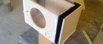
- Mark and cut plywood or plastic into 6 edges of the future body.
- Mark and drill holes for the corners.
- Cut out a large round gap for the speaker.
- From the top and/or side, cut out slots for the volume control, power switch, band switch, antenna and frequency control knob, guided by the assembly drawing.
- Install the radio board on one of the walls using “pile” type screw racks. Align the controls with the technological holes on the adjacent sides of the housing.
- Mount the power supply - or USB board with lithium-ion battery (for the mini radio) - away from the main board.
- Connect the radio board to the power supply board (or to the USB controller and battery).
- Connect and secure the magnetic antenna for AM and the telescopic antenna for FM. Securely insulate all wire connections.
- If a loudspeaker model is being manufactured, install the speaker on the front edge of the case.
- Using the corners, connect all the edges of the body to each other.
For the scale, calibrate the adjustment knob and place a mark in the form of an arrow next to it on the body. Install an LED for illumination.
8 photos
Recommendations for beginners
- To avoid overheating diodes, transistors and microcircuits, do not use a soldering iron with a power of more than 30 watts without flux.
- Do not expose the receiver to precipitation, fog, frost, or acid fumes.
- Do not touch the high voltage terminals of the power supply when the device under test is energized.
