So, what do you need to make a walkie-talkie?
To create a walkie-talkie you will need the following items:
- 4 MP-42 transistors and 3 P416B transistors;
- Resistors. You will need a lot of them: two pieces each. 3K, 160K, 4.7K, one each – 22K, 36K, 100K, 120K, 270K, and six pcs. 6.8 K;
- Capacitors: two 10 MK 10 V, 3300, 1000, 100, 6, 5-20, 22, 10 and one 5 MK 10 V – 4; 0, 0, 47 MK.
- Telescopic antenna;
- Microphones and speakers;
- Textolite boards - 2 pcs.
- Soldering iron;
- Socket;
- Wire cutters.
Almost all of the above is included in the special kit for radio amateurs JC986A. The further algorithm will be based on this set.
It is worth considering that creating your own walkie-talkie requires skills in working with a soldering iron and knowledge of how to determine the values of the elements.
iPTT - walkie-talkie for iOS
Even a small child can figure out how to make a walkie-talkie on an iPhone or iPad using this application - it’s so easy to use. By the way, iPTT is the first application of its kind in the AppStore, and it’s completely free.
Using this program, you can create a direct communication channel with both an individual recipient and a group of people. You can also select the “whisper” mode - confidentially communicate with one person from the group.
An application similar in functionality to iPTT will be TiKL Touch Talk Walkie Talkie. It is available for free not only for gadgets on iOS, but also on Android.
Necessary first steps before opening
The first thing to start with is completing the necessary documentation. First of all, you need to open a legal entity, for example, a company, the charter of which will indicate the following types of activities:
- creation of television and radio projects;
- advertising of a commercial and political nature;
- television and radio broadcasting;
- activities related to the media;
- the possibility of purchasing studio space for radio stations and various facilities used for radio broadcasting.
Preparation for activities
In this paragraph we will tell you how to create your own radio. When the necessary documents are completed, it’s time to register the media and begin developing the frequency. To do this, you will need to write an application for its provision. At all these stages, it is advisable to consult with a lawyer in order to make the best decision.
Before attempting to obtain a frequency, it is necessary to prepare information regarding what power the transmitter will be used, where it is intended to be located, and where the radio station itself will be located.
When calculating possible prospects, it is worth taking into account the fact that you cannot buy a radio frequency, since it is a state resource. It is not sold as a product, but is played out in a competition between applicants. In this regard, it may happen that someone else receives the frequency.
If this happens, don't despair. Sometimes the competition is won by the one who currently does not plan to carry out his own broadcasting on the received frequency. In this case, the conversation about renting it will be relevant.
How to create a radio wave from your phone: you will need an FM transmitter
An FM transmitter is also sometimes called an FM modulator. This is a special gadget that can convert the digital audio signal incoming to it into analog form and transmit it via radio waves. It is precisely such a device, for which they do not ask for too much money, that will be needed to solve the problem of the material - after activating the modulator on the radio, it will be enough to only select the required radio frequency.
An FM transmitter is a great way to use modern streaming services with any radio that is equipped with a radio. They can be cassette or disk: personally, I have not seen a single multimedia system without a radio, even in domestic models from the 80s.
Basic manufacturing rules
A home-made receiver must be mobile or portable. Soviet VEF Sigma and Ural-Auto radios, and the more modern Manbo S-202 are examples of this.
The receiver contains a minimum of radio elements. These are several transistors or one microcircuit, without taking into account the attached parts in the circuit. They don't have to be expensive. A broadcast receiver that costs a million rubles is almost a fantasy: this is not a professional walkie-talkie for the military and special services. The quality of reception should be acceptable - without unnecessary noise, with the ability to listen to the whole world on the HF band while traveling across countries, and on VHF - to move tens of kilometers away from the transmitter.
You need a scale (or at least a marking on the tuning knob) that allows you to estimate which range and frequency you are listening to. Many radio stations remind listeners what frequency they are broadcasting on. But repeating 100 times a day, for example, “Europe Plus”, “Moscow 106.2” is no longer in fashion.
The receiver must be dust- and moisture-proof. This will provide a housing, for example, from a powerful speaker that has rubber inserts. You can also make such a case yourself, but it is hermetically sealed on almost all sides.
Instructions
We will assemble the radio according to a proven scheme:
A1 – common antenna for receiving and sending a signal SA1 – power switch SA2 – switch connecting the power source and the radio station.
1. Making coils:
a. To make a cylindrical base with a diameter of 0.8 cm and a height of 2 cm, plexiglass, polystyrene or cardboard. b. We wrap the base with copper wire with a diameter of 0.5 mm in tight turns. c. We wind ten turns on coils d. We will wind coils L2 and L3 on the same base, observing the conditions: e. We wind four turns onto coil L2 . f. We place L2 between the windings of L3. g. L3 will consist of 8 turns with a wire outlet in the middle. h. Coils L4 and L6 each contain 200 turns . i. For the winding, we take a wire with a diameter of 0.1 mm j. We wind it around the body of an MLT-0.5 type resistor with a resistance of more than 1 MOhm.
2. The result should be as shown in the figure:
3. Now we prepare the printed circuit board 4. We arrange the radio components according to the diagram.
5. We make a printed circuit assembly from foil getinax. 6. We make a frame from centimeter-long scraps of copper wire inserted into holes with a diameter of about one millimeter.
Now you need to configure the radio:
1. We begin debugging by improving the signal:
a. 33-47 kOhm variable resistor . b. We achieve the loudest noise possible. c. We change the inductance level of coil L5 by adjusting the core. d. We are trying to improve the signal. e. We replace the connected variable resistor with R10 with the required resistance.
2. If the voice timbre is distorted during signal transmission, we select resistors R1 and R3 more carefully.
3. We debug the generator and antenna using a wave meter; its electronic circuit is shown below. Wave meter:
4. For the L1 wavemeter coil of ten turns of 1.2 mm wire, we use a frame with a diameter of 22 mm, the third turn from the bottom serves as a tap. 5. Capacitor C1 of the wavemeter must be made variable. 6. We place handle C1 of the wave meter opposite the current frequency of the radio. 7. Place the wave meter so that next to the L3 coil of the radio there is a L1 wave meter coil. 8. Thus, we make it a kind of indicator. 9. Instead of the C9 radio, we try capacitors of different capacities. 10. We achieve the maximum deviation of the wave meter needle. 11. We bring the wave meter to the antenna. 12. Rotate the L1 coil core of the radio. 13. We bring the antenna into resonance with the circuit frequency, tuning L3, C8 and C9. 14. We achieve the maximum deviation of the wave meter needle.
How to assemble a simple radio receiver?
There are several radio receiver circuits:
- detector;
- direct amplification;
- (super) heterodyne;
- on a frequency synthesizer.
Receivers with double and triple conversion (2 or 3 local oscillators in a circuit) are used for professional work at the maximum permissible, ultra-long distances.
The downside of the detector receiver is low selectivity: signals from several radio stations can be heard simultaneously. The advantage is that there is no separate power supply: the energy of the incoming radio waves is enough to listen to the air without powering the entire circuit. At least one repeater must be broadcasting in your area - in the range of long (148-375 kilohertz) or medium (530-1710 kHz) frequencies. When you are 300 km or more away from it, you are unlikely to hear anything. It should be quiet around - it is better to listen to the program using headphones with high (hundreds and thousands of ohms) impedance. The sound will be barely audible, but both speech and music will be understandable.
The detector receiver is assembled as follows. The oscillating circuit consists of a variable capacitor and a coil. One end of it is connected to an external antenna. Grounding is supplied through the building circuit, and the heating network pipes are supplied to the other end of the circuit. Any RF diode is connected in series with the circuit - it will isolate the audio component from the RF signal. A capacitor is connected to the resulting assembly in parallel - it will smooth out the ripples. To extract sound information, a capsule is used - the resistance of its winding is at least 600 Ohms.
If you disconnect the earphone from the DP and send a signal to a simple audio amplifier, then the detector receiver will become a direct amplification receiver. By connecting a MF or LW radio frequency amplifier to the input - to the circuit - you will increase the sensitivity. You can move up to 1000 km from the AM repeater. A receiver with a simple diode detector does not work on the (U) HF band.
To improve adjacent channel selectivity, replace the detector diode with a more efficient circuit.
To ensure selectivity in the adjacent channel, a local oscillator, a mixer and an additional amplifier are needed. A local oscillator is a local oscillator with a variable circuit. The heterodyne receiver circuit works as follows.
- The signal comes from the antenna to a radio frequency amplifier (RFA).
- The amplified RF signal passes through a mixer. The local oscillator signal is superimposed on it. A mixer is a frequency subtractor: the local oscillator value is subtracted from the input signal value. For example, to receive a station on 106.2 MHz in the FM band, the local oscillator frequency must be 95.5 MHz (10.7 remains for further processing). The value 10.7 is constant - the mixer and local oscillator are adjusted synchronously. Mismatch of this functional unit will immediately lead to the inoperability of the entire circuit.
- The resulting intermediate frequency (IF) of 10.7 MHz enters the IF unit. The amplifier itself performs the function of a selector: its bandpass filter cuts the spectrum of the radio signal to a band of only 50-100 kHz. This ensures selectivity on the adjacent channel: in the densely packed FM range of a large city, radio stations are located every 300-500 kHz.
- Amplified IF is a signal that is ready to be transferred from the radio frequency region to the audio frequency region. The amplitude detector converts the AM signal into audio, highlighting the low-frequency envelope of the radio signal.
- The resulting sound signal is sent to a low-frequency amplifier (LF) - and then to a speaker (or headphones).
The advantage of the (super) heterodyne receiver circuit is satisfactory sensitivity. You can move tens of kilometers away from the FM transmitter. Selectivity on the adjacent channel will allow you to listen to the radio station you like, and not to the simultaneous cacophony of several radio broadcasts. The disadvantage is that the entire circuit requires power - several volts and up to tens of milliamps of DC.
There is also selectivity along the mirror channel. For AM receivers (LW, MW, HF bands) the IF is 465 kHz. If in the CB range the receiver is tuned to a frequency of 1551 kHz, then it will “catch” the same frequency at 621 kHz. The mirror frequency is equal to twice the IF value subtracted from the transmitter frequency. For FM (FM) receivers operating in the VHF band (66-108 MHz), the IF is 10.7 MHz.
Thus, a signal from an aviation radio (“mosquito”) operating at 121.5 megahertz will be received when the receiver is tuned to 100.1 MHz (minus 21.4 MHz). To eliminate the reception of interference in the form of a “mirror” frequency, an input circuit is connected between the RF amplifier and the antenna - one or more oscillating circuits (a coil and a capacitor connected in parallel). The disadvantage of a multi-circuit input circuit is a decrease in sensitivity, and with it the reception range, which requires connecting an antenna with an additional amplifier.
The FM receiver is equipped with a special cascade that converts FM into AM waves.
The disadvantage of heterodyne receivers is that the signal from the local oscillator without an input circuit and in the presence of RF feedback enters the antenna and is re-radiated into the air. If you turn on two such receivers, tune them to the same radio station, and place them side by side, close together, a slight whistling of a changing tone will appear in the speakers of both. In a circuit based on a frequency synthesizer, a local oscillator is not used.
In FM stereo receivers, after the amplifier and detector, there is a stereo decoder. Stereo signal encoding at the transmitter and decoding at the receiver is carried out using pilot-tone technology. After the stereo decoder, a stereo amplifier and two speakers are installed (one for each channel).
Receivers that do not have stereo decoding function receive stereo broadcasts in monaural mode.
To assemble the receiver electronics, do the following.
- Drill holes in the workpiece for the radio board, checking the drawings (topology, arrangement of elements).
- Place radio elements.
- Wind the loop coils and magnetic antenna. Place them according to the diagram.
- Draw the tracks on the board, checking the topology from the drawing. Paths are made both by cutting and etching.
- Solder the parts onto the board. Check the correct installation.
- Solder wires to the antenna input, power supply and speaker output.
- Install controls and switches. A multi-range model will require a multi-position switch.
- Connect the speaker and antenna. Turn on the power supply.
- The noise of an untuned receiver will appear in the speaker. Turn the tuning knob. Tune to one of the available stations. The sound of the radio signal should be free of wheezing and noise. Connect an external antenna. You need to adjust the coils and shift the range. Choke coils are adjusted by rotating the core, frameless coils are adjusted by stretching and compressing the turns. They require a dielectric screwdriver.
- Select an extreme frequency on the FM modulator (for example, 108 MHz) and move the turns of the local dyne coil (it is located next to the variable capacitor) so that the upper end of the receiver range stably receives the modulator signal.
Assemble the body:
- Mark and cut plywood or plastic into 6 edges of the future body.
- Mark and drill holes for the corners.
- Cut out a large round gap for the speaker.
- From the top and/or side, cut out slots for the volume control, power switch, band switch, antenna and frequency control knob, guided by the assembly drawing.
- Install the radio board on one of the walls using “pile” type screw racks. Align the controls with the technological holes on the adjacent sides of the housing.
- Mount the power supply - or USB board with lithium-ion battery (for the mini radio) - away from the main board.
- Connect the radio board to the power supply board (or to the USB controller and battery).
- Connect and secure the magnetic antenna for AM and the telescopic antenna for FM. Securely insulate all wire connections.
- If a loudspeaker model is being manufactured, install the speaker on the front edge of the case.
- Using the corners, connect all the edges of the body to each other.
For the scale, calibrate the adjustment knob and place a mark in the form of an arrow next to it on the body. Install an LED for illumination.
8 photos
Recommendations for beginners
- To avoid overheating diodes, transistors and microcircuits, do not use a soldering iron with a power of more than 30 watts without flux.
- Do not expose the receiver to precipitation, fog, frost, or acid fumes.
- Do not touch the high voltage terminals of the power supply when the device under test is energized.
How to set up high-quality music playback from an FM modulator
Of the problems associated with the operation of a repeater, only two fall into the category of mass ones:
- Interference, extraneous noise in the form of wheezing and hissing when playing music in the car.
- Low quality of reproduced audio.
The main dissatisfaction with the first use of an FM transmitter is that the final sound quality is even worse than that of any city radio with a good signal. In particular, the device “cuts” low and high frequencies well. As a result, the audio sounds even worse than from the disc.
That is why competent drivers advise using a wired connection (AUX output). By the way, some FM modulators allow you to establish such a connection with standard acoustics, and thus establish a connection between a USB flash drive and an old car radio.
There is another way out. If you do not belong to the caste of audiophiles, you can improve the situation with the equalizer built into the FM repeater:
- Turn off the high pass filter.
- Lower the low pass filter to 160 Hz.
- Add units to "low" and "high" in the appropriate categories.
If you have preset programs, select “POP” or “JAZZ” in the equalizer menu.
How to make a walkie-talkie with your own hands - a simple diagram
We present a simple and working diagram of a walkie-talkie that you can assemble with your own hands.
Required Parts
- Transistors: 3xP416B and 4xMP42.
- Resistors: 2x3K, 2x160K, 2x4.7K, 22K, 36K, 100K, 120K, 270K, 6x6.8K;
- Capacitors: 2x10MK (10V), 2x3300MK, 2x1000MK, 2x100MK, 2x6MK, 2x5–20MK, 22MK, 10MK, 0.047MK, 4x5MK (10V).
- Antenna.
- Microphone, speaker.
- Switch, switch.
- DC source.
- 2 PCB boards.
- Wires.
- Wire with a diameter of 0.1 mm and 0.5 mm.
Installation sequence
- The common antenna for receiving and sending the signal is A1.
- Power switch - SA1.
- The switch connecting the homemade radio station to the current source while sending the signal to the transmitter and receiver upon receipt is SA2.
Number of turns:
- Coils L1 and L5 - 10 turns.
- Coil L2 has 4 turns and is located between the halves of the winding of coil L3, which contains 8 turns and has a wire tap in the middle.
- Coils L4 and L6 - 200 turns, 0.1 mm wire around the MLE-0.5 resistor with min. resistance 1 Mohm.
Well, the coils for the radio are ready. We continue making the radio with our own hands:
- We place the parts on two boards (one of which has a master oscillator, and the other with a receiver and a low-frequency amplifier) on one side.
- We connect them with an insulated wire (diameter 0.2–0.3 mm) on the reverse side.
- We connect using a stranded wire insulated with vinyl chloride to the battery.
Printed wiring can be done if you have a foil getinax, and for the frame of a homemade walkie-talkie, centimeter-sized pieces of wire driven into holes with a diameter of 1 mm are suitable.
The windings of the coils and chokes should be mutually perpendicular, and the C15 handle should be on the front panel of the radio. The generator must be separated from other parts by a tin screen.
Configuring and debugging the radio
Debugging begins with improving the reception quality; to do this, you need to replace R10 with a variable one with a resistance of 33–47 kOhm and wait for the maximum noise volume. Next, using a tuning core, we change the inductance L5, achieving the highest quality signal. After this, we return the previous resistor.
- Micro-earphone circuit for passing the exam
If the voice timbre of your walkie-talkie is strongly distorted during signal transmission, you need to select R1 and R3 more carefully.
DIY FM radio at home
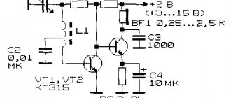
One of the most popular amateur radio designs is the pocket radio. Of course, in our era of the total proliferation of mobile phones and pagers, the manufacture of homemade communication equipment has lost its relevance. However, in some cases, an FM radio may be indispensable, since it works regardless of the coverage of cellular stations. Let's look at how to make a simple, proven FM radio with your own hands based on a 4-transistor transmitter and receiver at a frequency of 100–105 MHz. The figures below show a diagram of the receiving and transmitting parts of the radio station, respectively.
Winding data of coils and chokes: receiving L1 and L2, 8 turns of PEV0.6 each on a 4 mm mandrel. Transmitting - 10 turns with a tap from the middle at a diameter of 4 mm. The chokes are 5–10 μH each, they are wound on 0.25-watt resistors 100–500 Ohms with a 0.2 mm wire in the amount of 50 turns.
The tested printed circuit board can be downloaded in the archive. Files for download: raciya-fm-diapazona.rar The FM band was not chosen by chance. It will be easiest for beginning radio amateurs to work with it, since the transmitter can be set up using a regular FM broadcast receiver. After setting up the transmitter, we ensure that the receiving unit is operational. To do this, you can listen to FM broadcast stations 88–108 MHz. Only after this you need to increase the frequency to 110–120 MHz to prevent accidental listening to your conversations on other receivers.
The operation of the units has no special features, and any “bug builder” with little experience will be able to run them without problems. The radio is powered by a 9–12V battery. Moreover, power supply from a stationary power supply is possible. This will turn it into a broadcast radio station (remember about the power limitation, according to the law). Well, the RX part works great as an FM radio receiver, which makes it possible to simply listen to music with it.
How to connect an FM transmitter to a car radio
Before connecting the gadget to the car stereo, you need to supply power to it. Like a mirror-video recorder with a camera for recording the interior, almost all modern models of repeaters are powered from the cigarette lighter socket. This is convenient, but at the same time causes discomfort, since there is usually only one such outlet in the car. The tee solves this problem, but the final design is bulky and spoils the integrity of the car's interior. The optimal solution is to move the additional 12V socket to a convenient and inconspicuous place and connect the radio wave modulator to it. When the power supply issue is resolved, start setting up.
Conventionally, models of FM transmitters can be divided into two classes with and without Bluetooth function. We introduced the division for a reason - these devices are configured differently, which is why it would not be entirely correct to combine their setup into one manual.
How to configure the radio to receive a signal from a USB/Flash FM modulator
- Install the flash drive into the transmitter.
- Connect the device to the on-board network via the cigarette lighter.
- Turn on the radio on the car radio and find a free frequency. Remember it.
- Configure the repeater to the radio frequency found in the previous paragraph. Settings are performed either using the keys on the gadget itself, or using the remote control that comes with it. The buttons are more commonly referred to as “CH-” and “CH+”.
How to enable the car radio to receive from a Bluetooth FM transmitter
The basic idea of connecting a car multimedia system with a modulator remains the same - both devices must operate on the same radio frequency, which must be free from airwaves. Using the Xiaomi Roidmi 3S as an example, we can note the first feature of setting up this group of devices: the radio channel on the repeater is selected in the mobile application.
To do this, you need to insert the transmitter into the cigarette lighter socket and connect to it from your phone via Bluetooth. By default, a certain frequency will already be set (for Roidmi 3S it is 96.4 MHz). The Bluetooth connection is monitored visually - by the operating mode of the LED on the modulator:
- The lamp blinks - the connection is not established.
- The LED is on - the smartphone has successfully connected to the auto gadget.
In general, there are plenty of settings in the mobile offer. For example, it is possible to activate the function of switching music tracks by shaking the phone, and check the box next to Hands-free mode. You can also play around with the equalizer settings. By the way, experienced owners of FM modulators have high hopes for this instrument, and we will tell you why.
My modernization
I made such a walkie-talkie back in school, but then I already changed all the transistors to more modern ones with a high gain. For example, I replaced VT1, VT2 with KT361, and VT3 with KT315. Now, of course, I would change the polarity of the power supply and the polarity of the capacitors, replace all the transistors from the npn structure to pnp, and pnp to npn. Well, I would install modern transistors. There are no particular requirements for transistors, so absolutely any will do. The author of the diagram says that the range of action of radiums of the same type in open areas is 100-200 meters. I accelerated such radios to 500 meters, for this I used modern transistors, increased the antenna to 900 mm, plus increased the generator current by replacing the 100 Ohm resistor with a 50 Ohm one. Someone will say that it’s all due to the increase in the antenna, with which I disagree and will say that with the “native” antenna I was able to communicate over 300 meters.
Video transmitter circuit
There is nothing special to explain about the operation of the circuit: a SAW master oscillator (surface acoustic wave resonator), UHF, amplitude modulator with adjustable level, linearity and modulation depth. The transmitter power supply is 6 volts, the current consumption is about 180 mA, the power in the antenna is about 100 mW, the signal in the apartment is reliable through 3 walls, the picture quality is excellent! When you pull the antenna, the picture does not break. The antenna was originally taken from PEV-2 1.5 wire, length 20 cm. The dimensions of the board of the first assembly option are 43 x 36 mm, standard size SMD 1206, coils - SMD 1210.
Popular articles Decorating a lantern
A cheap color camera from a video eye was taken as a signal source. A computer webcam will not work here; an analog signal is needed. And the webcam, as you know, is digital.
On the receiving side, an ordinary small black and white TV with low sensitivity was used - on purpose. The video signal transmitter board is double-sided, the bottom layer of foil is a solid screen connected to the ground of the front side.
In the original circuit there was no 4.7 pF capacitor - the generator OS worked on parasitic capacitance, so it may be needed.
After successful tests, I redesigned the board with a mounting seal and a transition to SMD elements of size 0805, inductance size 1008. The surfactant, as SMD planned, has not yet been found, so I had to sculpt a lead-out one (the dimensions of the board do not change). They are in whitefish, they are in keychains for them, they are in Chinese radio calls, but the thing is not very common. You can view the surfactant table here.
The signal is very reliable, even with the antenna on the TV folded, the picture quality is not lost. The quality of the received signal is almost like over a wire. The scheme with modifications started immediately and without configuration. The size of the new board is now 27.5 x 26.5 mm, see what happened in the photo:
This is the board of the latest version, more compact, the arrow indicates the jumper above the transistor. I packed a video transmitter into the case, and then the plan is to build a DC-DC converter from a Li-Ion battery.
Now about the operating range of the video transmitter. The author promises up to 300 meters in color and up to 500 meters in b/w mode. But we conducted an experiment in terms of range and the result was superior! Confident reception range of more than 800 meters! The receiving antenna is a native 50 cm TV telescope. The transmitter power supply is almost 5 volts, the current consumption is 120 mA, it can be raised to 6 V, the current increases to 180 mA. accordingly the range. The transmitter was assembled and tested by the GOVERNOR.
Discuss the article VIDEO SIGNAL TRANSMITTER
Detector simplest radio receiver: basics
The story touched on dental fillings for a reason. Steel (metal) is capable of converting ethereal waves into current, copying the simplest radio receiver, the jaw begins to vibrate, the bones of the ear detect the signal encrypted on the carrier. With amplitude modulation, the high frequency repeats the speaker's voice, music, and sound in scope. The useful signal contains a certain spectrum, which is difficult for a layman to understand; it is important that when adding the components, a certain law of time is obtained, following which the speaker of a simple radio receiver reproduces the broadcast. At the dips, the jaw bone freezes, silence reigns, and the ear hears the peaks. God forbid, of course, you should have a simple radio receiver.
The reverse piezoelectric effect changes the geometric dimensions of the bones according to the law of electromagnetic waves. A promising direction: a human radio receiver.
The Soviet Union was famous for launching a space rocket, ahead of the rest, for scientific research. Union times encouraged degrees. The luminaries have brought a lot of benefit here - designing radios - and earn decent money over the hill. The films promoted the smart, not the wealthy, it is not surprising that the magazines are full of various developments. A series of modern lessons on creating simple radios, available on YouTube, is based on magazines published in 1970. Let’s be careful not to deviate from traditions; we will describe our own vision of the situation in the amateur radio industry.
The concept of a personal electronic computer was developed by Soviet engineers. The party leadership recognized the idea as unpromising. Efforts have been devoted to building giant computer centers. It is too much for a worker to master a personal computer at home. Funny? Today you will encounter more amusing situations. Then they complain - America is shrouded in glory, printing dollars. AMD, Intel - have you heard? Made in USA.
Everyone can make a simple radio receiver with their own hands. An antenna is not needed, there is a good stable broadcast signal. The diode is soldered to the terminals of high-impedance headphones (discard computer ones), all that remains is to ground one end. To be fair, let’s say the trick will work with the good old Soviet-made D2, the taps are so massive that they will serve as an antenna. We get the earth in the simplest radio receiver by leaning one leg of the radio element against a heating radiator that has been stripped of paint. Otherwise, the decorative layer, being the dielectric of the capacitor formed by the leg and metal of the battery, will change the nature of the operation. Try it.
The authors of the video noticed: there seems to be a signal, represented by an unimaginable jumble of rustles and meaningful sounds. The simplest radio receiver lacks selectivity. Anyone can understand and understand the term. When we set up the receiver, we catch the desired wave. Remember, we discussed the spectrum. The air contains a bunch of waves at the same time, you will catch the one you need by narrowing the search range. There is selectivity in the simplest radio receiver. In practice, it is implemented by an oscillatory circuit. Known from physics lessons, it is formed by two elements:
- Capacitor (capacitance).
- Inductor.
Let's take a moment to study the details; the elements are equipped with reactance. Due to this, waves of different frequencies have unequal attenuation as they pass by. However, there is some resonance. For a capacitor, the reactance in the diagram is directed in one direction, for an inductance - in the other, and the frequency dependence is shown. Both impedances are subtracted. At a certain frequency, the components equalize, and the reactance of the circuit drops to zero. Resonance sets in. The selected frequency and adjacent harmonics pass through.
The physics course shows the process of choosing the bandwidth of a resonant circuit. Determined by the attenuation level (3 dB below maximum). Let us present the theory, guided by which a person can assemble a simple radio receiver with his own hands. In parallel with the first diode, a second one is added, connected oppositely. It is soldered in series to the headphones. The antenna is separated from the structure by a 100 pF capacitor. Let us note here: the diodes are endowed with pn-junction capacitance, minds apparently calculated the reception conditions, which capacitor is included in the simplest radio receiver endowed with selectivity.
We believe we will slightly deviate from the truth when we say: the range will affect the HF or SV regions. Multiple channels will be received. The simplest radio receiver is a purely passive design, devoid of an energy source; one should not expect great achievements.
A few words about why we discussed remote nooks where radio amateurs crave experiments. In nature, physicists have noticed the phenomena of refraction and diffraction, both of which allow radio waves to deviate from their direct course. Let's call the first one rounding obstacles, the horizon moves away, giving way to broadcasting, the second - refraction by the atmosphere.
LW, SW and HF are caught at a considerable distance, the signal will be weak. Therefore, the simplest radio receiver discussed above is a touchstone.
How to make a walkie-talkie with your own hands - 3 working diagrams
- Simple scheme
- DIY FM radio
- How to make a walkie-talkie for negotiations - diagram, instructions
- Video
Today we will look at three of the simplest and most working schemes for creating walkie-talkies with your own hands. The first project involves the manufacture of the device by beginners according to the simplest scheme. Recommendations, step-by-step photos and installation instructions will help you understand all the nuances of installation. The second project is an FM radio. This device is a little more complicated to manufacture, but it will not be difficult for novice radio amateurs to set up the transmitter using a regular FM broadcast receiver. The third project is a walkie-talkie. We recommend creating 2 devices at once that can be used for communication in everyday life.
Zello-walkie-talkie application
The most convenient and easiest way to experience the beauty of talking on a walkie-talkie is to install an application with this function on your smartphone. The leader among them is Zello, which can also be installed on a laptop or PC. The program is completely free for all existing operating systems. Zello is often used by mobile software developers - it allows them to add the function of communicating via walkie-talkie to their applications.
Zello uses Wi-Fi or mobile Internet to transmit voice. The application also supports Bluetooth headset. Your voice message is first saved by the system and then sent to the recipient. Zello supports communication between 800 interlocutors, displays their connection status, stores voice message histories, and creates special password-protected channels.
How to make a walkie-talkie with your own hands - a simple diagram
We present a simple and working diagram of a walkie-talkie that you can assemble with your own hands.
Required Parts
- Transistors: 3xP416B and 4xMP42.
- Resistors: 2x3K, 2x160K, 2x4.7K, 22K, 36K, 100K, 120K, 270K, 6x6.8K;
- Capacitors: 2x10MK (10V), 2x3300MK, 2x1000MK, 2x100MK, 2x6MK, 2x5–20MK, 22MK, 10MK, 0.047MK, 4x5MK (10V).
- Antenna.
- Microphone, speaker.
- Switch, switch.
- DC source.
- 2 PCB boards.
- Wires.
- Wire with a diameter of 0.1 mm and 0.5 mm.
Installation sequence
- The common antenna for receiving and sending the signal is A1.
- Power switch - SA1.
- The switch connecting the homemade radio station to the current source while sending the signal to the transmitter and receiver upon receipt is SA2.
Coils L1 and L5 - 10 turns.
- Coil L2 has 4 turns and is located between the halves of the winding of coil L3, which contains 8 turns and has a wire tap in the middle.
- Coils L4 and L6 - 200 turns, 0.1 mm wire around the MLE-0.5 resistor with min. resistance 1 Mohm.
Well, the coils for the radio are ready.
We continue making the radio with our own hands:
- We place the parts on two boards (one of which has a master oscillator, and the other with a receiver and a low-frequency amplifier) on one side.
We connect them with an insulated wire (diameter 0.2–0.3 mm) on the reverse side.
- We connect using a stranded wire insulated with vinyl chloride to the battery.
Printed wiring can be done if you have a foil getinax, and for the frame of a homemade walkie-talkie, centimeter-sized pieces of wire driven into holes with a diameter of 1 mm are suitable.
The windings of the coils and chokes should be mutually perpendicular, and the C15 handle should be on the front panel of the radio. The generator must be separated from other parts by a tin screen.
Configuring and debugging the radio
Debugging begins with improving the reception quality; to do this, you need to replace R10 with a variable one with a resistance of 33–47 kOhm and wait for the maximum noise volume. Next, using a tuning core, we change the inductance L5, achieving the highest quality signal. After this, we return the previous resistor.
- Micro-earphone circuit for passing the exam
If the voice timbre of your walkie-talkie is strongly distorted during signal transmission, you need to select R1 and R3 more carefully.
Sources
- https://tytmaster.ru/raciya-svoimi-rukami/
- https://BusinessMan.ru/new-kak-sozdat-svoe-radio.html
- https://stroy-podskazka.ru/radiopriemniki/svoimi-rukami/
- https://indevices.ru/hi-tech/kak-sdelat/raciju.html
- https://tehnoobzor.com/schemes/transmitters/2855-kak-sdelat-raciyu-svoimi-rukami-3-rabochie-shemy.html
- https://SdelaySam-SvoimiRukami.ru/3941-prostaya-raciya-na-treh-tranzistorah.html
- https://VashTehnik.ru/radioapparatura/radiopriyomnik-svoimi-rukami.html
- https://vsepomode39.ru/vse-stati/kak-sdelat-ratsiyu-iz-bumagi.html
[collapse]