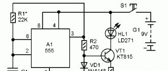
Simple automatic telephone intercom
Let's look at the operation of the device according to its schematic diagram. The initial state of the circuit is when both devices are on-hook. Let’s assume that subscriber AB-1 picks up the phone. A line loop is formed (DC circuit), relay A, relay IN are activated (plus with VD1, relay winding IN, resistor R1, relay winding A, device AB-1, “ground”). Having triggered, relay A will switch its contact 1-2 to position 1-3, and relay IN will close contacts 1-2 and switch the inductor (ringing) voltage from winding III of transformer T1, which through contacts 1-2 of relay B, capacitors C3, C4 will be sent to the second subscriber's telephone. When telephone AB-2 is picked up, relay B will operate, the calling circuit will open, and contacts 1-3 of relay B will create a conversational circuit with AB-1. The voltage for powering telephone microphones is supplied through the IN relay winding, which simultaneously serves as a choke, preventing the conversation circuit from being bypassed by the power source. Capacitors C1 and C4 are needed to pass conversational and calling currents bypassing the relay windings. The circuit automatically returns to its original state when both telephone sets are on-hook. If at the end of the conversation one of the subscribers does not return the handset to its original state, then the other subscriber’s bell will ring. This drawback can be eliminated by complicating the circuit and using relays with other groups of contacts or additional relays, which is hardly justified in this case. Simple correct use of this device is enough.
The length of communication lines can be several kilometers and is limited only by the voltage of the power source (for long lines, the voltage of winding II must be increased). Any relay with one contact group for switching, with an operating current of 5...10 mA and a switching voltage of the contact group not lower than the inductor voltage (in this case, alternating, 80 volts) is suitable as subscriber relays A and B. Possible types of relays used and their parameters are given in the table.
| Relay type and passport number | Winding resistance, Ohm | Triggering current, mA | Release current, mA | Operating voltage, V. |
| RES-9 | ||||
| RS4.524.204 | 9600 | 7 | 1,1 | 8,3…9,3 |
| RS4.524.205 | 3400 | 11 | 1,7 | 13…15 |
| RS4.524.208 | 9600 | 7 | 1,1 | 8,3…9,3 |
| RS4.524.217 | 9600 | 7 | 1,1 | 8,3…9,3 |
| RS4.524.218 | 3400 | 11 | 1,7 | 13…15 |
| RS4.524.230 | 3400 | 11 | 1,7 | 13…15 |
| RES-10 | ||||
| RS4.524.301 | 4500 | 8 | 1,1 | 9,5…10,5 |
| RS4.524.313 | 4500 | 8 | 1,1 | 9,5…10,5 |
| RS4.524.316 | 1600 | 10 | 1,3 | — |
| RES-15 | ||||
| RS4.591.001 | 2200 | 8,5 | 2 | — |
| RS4.591.007 | 1200 | 11,4 | 3 | — |
| RES-22 | ||||
| RF4.500.122 | 2500 | 10,5 | 3,5 | 43,2…52,8 |
| RF4.500.124 | 2800 | 11 | 3,5 | 54…66 |
| RF4.500.125 | 2800 | 11 | 3,5 | 54…66 |
| RF4.500.130 | 2500 | 10,5 | 3,5 | 43,2…52,8 |
| RES-34 | ||||
| RS4.524.371 | 4200 | 8 | 1,2 | — |
| RS4.524.375 | 4200 | 8 | 1,2 | — |
| RES-49 | ||||
| RS4.569.000 | 1900 | 8,3 | 0,8 | 24…30 |
| RS4.569.001 | 1900 | 8,3 | 0,8 | 24…30 |
| RS4.569.423 | 1900 | 8 | 1,6 | 22…36 |
| RS4.569.427 | 1900 | 8 | 1,2 | 22…36 |
| RS4.569.428 | 1900 | 8 | 1,6 | 22…36 |
| RS4.569.429 | 800 | 12 | 2,2 | 16…20 |
| RS4.569.430 | 1900 | 8 | 1,2 | 22…36 |
| RES-54 | ||||
| HP4.500.010 | 4000 | 2,6 | 0,3 | 22…32 |
| HP4.500.011 | 4000 | 3,6 | 0,4 | 24…33 |
| RES-60 | ||||
| RS4.569.436 | 1700 | 8,4 | 1,8 | 22…34 |
The relay pin numbers and their diagram are shown in the attached figures. Any relay can be used as an IN inductor relay, preferably with a large number of winding turns, because the winding of this relay also acts as a choke (as mentioned above). You can use relays of the type RES-6, RES-9, RES-10, RES-15, RES-22 or any others with a switching voltage of the contact group not lower than the inductor voltage. Other types of relays can be used in this design. For example, relays of the type RPN, RES-14 are suitable (relays of this type are used at coordinated telephone exchanges), you can use relays from telephone blockers and diode-relay attachments (DRP).
The transformer can be anything that provides the required output voltages. When choosing a transformer, remember that the inductor voltage winding must provide a current of at least 100 mA. If the device is operated with short communication lines, the voltage of the inductor winding may be below 50 volts, because calls for most telephone sets (including electromechanical ones) can work normally at a reduced ringing voltage, up to 35 - 40 volts. You can use a transformer with the following data: core - Ш16х45, windings: I (network) - 1320 vit. PEV-2, cross-section 0.23 mm., II - 110 vit. PEV-2, cross-section 0.35 mm., III (inductor) - 500 vit. PEV-2, cross-section 0.12 mm.
Capacitors C1 - C4 type MBM, MBGO, operating voltage not lower than 160 volts, their capacity can be in the range of 0.5...4 μF. Instead of resistors R1 and R2, it is better to use chokes with a large number of turns. You can use ready-made ones from old tube TVs. Relay windings, primary windings of network or audio transformers can be used as chokes. Resistor R3 serves to limit the ringing current and also protects winding III of the transformer from a possible short circuit (short circuit) in the event of damage on the line. The resistance of resistor R3 can be in the range of 50...150 ohms. If possible, instead of R3 it is better to use a miniature 60-volt incandescent lamp (the kind used in telephony). This activation will allow you to visually monitor the status of the called subscriber’s line, for example: if the light is dim, the line is working; in bright light - on the K.Z. line; if there is no glow, the line is broken. Diode bridge VD1 - KTs402, KTs405, KTs409 with any letter, you can use rectifier diodes for a current of at least 0.3 A. Installation of the device circuit is carried out using a hinged method. Telephone sets of any type for two-wire communication, without a dialer or with a faulty dialer. No circuit adjustment is required. In some cases, when an inductor (ringing) voltage is applied, the subscriber relay may operate. In this case, you should make sure that the bypass capacitor C1 is working properly if relay A (or C4 for relay B) operates. The relay can also be triggered for another reason: since the relay winding has a high inductance, the parallel connection of the winding and capacitor forms a circuit, the resonant frequency of which can coincide with the frequency of the ringing current (in this case, 50 Hz). In this case, it is enough to change the capacitance of the capacitor. And in conclusion, some advice for those who are dealing with wired telephone communications for the first time.
- To lay telephone lines, use wires manufactured for telephony or radio networks.
- For long communication lines (100 m or more), the wire must be “paired”, i.e. both cores must be located together along the entire length of the line, otherwise all sorts of noise will be heard in the line.
- When laying communication lines in buildings and structures, avoid parallel runs with network wires and radio network wires. The recommended distance between the communication line and network wires for parallel runs is at least 25 cm.
- When crossing power cables and wires, the recommended visible distance between the communication line and the power wire is at least 5 cm.
- When laying communication lines in buildings where there are local computer networks, avoid parallel laying with a network cable, because the inductor current has a large amplitude and can serve as a source of local network failures.
- To organize communications over long distances (several kilometers), it is possible to use unused overhead communication lines and wire broadcasting, which were usually carried out with steel wire. In this case, to protect against lightning and the entry of extraneous voltage into the line, it is necessary to install lightning arresters at both ends of the line, and also install a 0.15 - 0.25 A fuse at the break of each wire.
Literature: Rodichev N. Intercom with automatic calling. - To help the radio amateur, issue 105, pp. 66 - 67. Handbook of the radio amateur - designer, M. Radio and Communications, 1984.
V. Sinitsky “Through life with a soldering iron”
Source: shems.h1.ru
Phone ringing
To test the telephone plug cable, you need to disconnect this cable from the telephone circuit. Here you can notice that the contact connections are numbered, which you should pay attention to when further connecting the cable (photo 4).
This photograph shows an image of the cable connector, the connector of which is connected to the telephone circuit (photo 5).
To check the telephone cable for continuity of the wires, you can use an indicator screwdriver (photo 6). The telephone cable consists of two wires and the photographs show how to use an indicator screwdriver for this test.
That is, the indicator screwdriver must be connected to the contact of the cable connector (photo 5), and the index finger of the second hand must be connected to the pin of the telephone plug. During the inspection, a break was detected in one of the cable wires (photo 6, right).
Call options
The simplest options that are installed on the entrance gate are wired devices. This design is represented by an open electrical circuit. At the moment of its closure, sound occurs.
Complete kit for wired installation
Wired calls
Such calls can be divided into two main types:
- Electromechanical option. During operation, when you press a button, the sound transfers to a coil containing an electric magnet. The main part of this coil is connected to the mechanism, which begins to move. This causes the hammer to strike the plate, creating a signal. Its sound will depend on the size of the resonator itself.
- Wired electronic type device. This variety is similar to the previous one, but there are also differences in internal composition. Thus, after the initial signal, the sound does not come from the hammer hitting the plate, but from the operation of the electronics. This version has several ringing tones and volume control.
Example of placement with a supply voltage of 12V
The main advantages of using wired calls:
- durability;
- reliability;
- low cost.
Scheme of assembly of the structure with power wires
Disadvantages of the device:
- connection to an electrical network is required for operation;
- installing a bell of this type is not easy, so you need to involve an electrician in the work;
- During the installation process it will be necessary to violate the integrity of the walls (drill them).
There is one more feature in installing a wired bell - it is installed before starting all kinds of finishing work or before installing the door, since the walls will be damaged during the work.
Microphone and speaker mount
Wireless calls
A wireless doorbell is often installed in private homes. The button is attached to the gate or wicket, and the notification is sent to the living space itself. If we refer to the principle of operation, it is similar to the operation of a wired device, but in this embodiment, after pressing the button, an alert is transmitted to the main device using a radio signal.
Procedure for installing a wireless signal
Paying attention to the power supply, it is worth noting that the wireless call is charged from a battery or batteries.
Principle of operation
The main components of intercoms are two remote controls installed at sites and a two-wire communication line connecting these remote controls. Each remote control is a communication device with an amplifier and a dynamic head. The last element can be dual purpose. During the transmission of messages, the dynamic head acts as a microphone, and during reception it is used for its intended purpose - to convert an electrical signal of audio frequency into sound.
In most intercoms, the signal amplified by the head travels from one device to the dynamic head of another via a direct communication line. Due to the low resistance of the head, losses occur in the communication lines: the sound volume begins to fall as the distance increases. Therefore, the operation of these systems is limited by distance depending on the scheme used.
It is quite possible to avoid losses on the line if the output signal from one remote control is supplied not to the dynamic head, but to the amplifier of another device, which has a significantly higher resistance. It is this connection that allows signal reception and transmission to reach several kilometers, without any significant losses. A significant advantage of such intercoms is the ability to be powered from a low voltage source.
How to flash
To flash a homemade phone, provide a connector on the board in advance for connecting to a computer, laptop or special programmer. As a rule, such a port is already provided if you buy a partially finished board. Manufacturers already assume that you will have to program it through external devices.
For flashing, you will need another intermediary, even if you are using a computer - a programmer. Here are two as examples:
- ATAVRISP2, comes with its own software, connects to a computer via a USB connector;
- USBASP – suitable for third-party programs for flashing microcircuits, connects similarly to the previous option, uses a 10-pin ISP interface to connect to the microcircuit.
To work, use one of the programs:
- AVRdude;
- AVRdude_Prog;
- Bascom-AVR;
- Khazama AVR Prog;
- eXtreme Burner AVR.
They support modern operating systems of the Windows, Mac, and Linux families. Not all of the programs listed are Russified.
Try programming the AVR using Assembler or C languages.