Add a link to the discussion of the article on the RadioKot forum > Laboratory > Amateur Radio Technologies >
| Article tags: | Add a tag |
Homemade equipment from a radio amateur workshop.
“To do something simple is always much more difficult than to do it difficult.”
The more devices, tools and equipment a radio amateur has, the more his creativity brings positive emotions, satisfaction and the final result. There is no such thing as too many tools. There is a lot you can do yourself and can do. When making the above equipment, I set myself several principles:
1. Easy to manufacture.
2. Minimize machine work.
3. Make maximum use of purchased consumer goods.
4. Use bins.
1. Mounting table. Dimensions: 320mm x 250mm.
Made for soldering SMD components. I found it so comfortable at work that I practically rooted myself to my desk. Soldering, small print, precision cutting of stickers....etc., etc.
It is convenient that the running tool is nearby and does not take up space on the desktop. For repeaters, I recommend increasing the number of tools located on the side wall.
It will be at hand and will not clutter up the work space.
The lens is not secured. It is located in a ring of 10mm plywood and lies freely on a fiberglass ring-board of LEDs. This is more convenient than rigid fastening of the line.
The ring with the lens moves freely on a D=6mm rod in two planes, rotates around the rod and can be raised and lowered by 60mm. This is quite enough.
The design of the lift-and-turn bushing is simple.
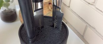
Toothpick - the needle is attached to a steel rod D=4mm made from the spokes of a suspended ceiling.
There is a soldering iron on a rotating stand. The bracket securely holds a soldering iron from 25 to 100W
A block of network sockets is fixed on the outside of the side wall.
It has a built-in backlight switch, an input from the network adapter, and inside there is a simple voltage stabilizer (error in the photo) for ms7805.
The backlight LEDs are powered through this stabilizer from a standard network adapter. I don’t see the point in sculpting a separate power supply.
I recommend installing the socket block as long as the side wall is long enough; during operation there are always a lot of 220V consumers to power. My three pieces are not enough.
From the first day, the table became the most convenient tool in the workplace. I recommend it for production, especially for people of the older generation who have developed vision problems.
2. Winding of UPS transformer coils.
Dimensions: 230mm x 200mm
It was made in one evening, but the quality of the transformer coils and ease of use are not comparable to manual winding. The transformer winds for no more than an hour and is a pleasure. The manufacturing quality of small reels is especially improved. The protective barrier without this winder always turned out to be disgusting.
It is not rational to install counters, drives, stackers for such coils with several dozen turns. The winder is so simple that everything is clear from the photographs. The stand and tee of the winder are from a plumbing store, bearings are from an auto shop. No machine tools were used in production.
- The bearings are inserted into the tee, tightened with a bolt and a twist handle is soldered to it.
- Everything from a plumbing store.
- The threaded bushing is screwed tightly into the socket.
- A thread is cut on a steel spoke from a suspended ceiling D=4mm and the spoke is soldered to the twist bolt.
The attachment of the winding reel to the axis can be done in any way. There are many different options.
- The nests were drilled with a carpenter's pen to the required depth.
The winder is small and very convenient for the manufacture of small-sized UPS transformers.
I always wound them without enthusiasm, but with the winder it became convenient and fast, despite the elementary simplicity of the design. The quality of wire laying and insulation is not comparable to manual winding.
This is not only a subjective assessment, but also measuring the parameters of transformers shows an improvement in the quality of their manufacture.
3. Lifting table for drilling. Dimensions: 150mm x 150mm x 100mm
They gave me the skeleton of a drill. Restored. I replaced the engine, inserted a switching power supply, work area lighting, a cartridge, etc. But the drill turned out to have a congenital defect: a large horizontal play; the drill is fed by a rack and pinion mechanism.
It is impossible to correct this defect with a little blood. But if the mountain does not come to Mohammed, then Mohammed goes to the mountain. A lifting table was made. The height of the table is calculated based on ergonomic considerations.
So that your hands rest on the work table when working, but it is also good for your eyes to see the place of drilling.
- The table is raised on four racks, this reduces backlash.
- The posts and bushings are glued into the surface of the table.
- The lifting mechanism and power microswitch are installed on an L-shaped steel plate.
The microswitch controls the intermediate relay for powering the electric motor. The table rises and the engine turns on. Very convenient. The microswitch button is pressed by a screw screwed into the top surface of the table. He is visible in one of the photographs.
When the plug is disconnected, the motor is controlled by the drill switch. An additional pulse current stabilizer is made on the power supply board to power a 1W LED for illuminating the work area.
The table turned out to be practically play-free, at a convenient height for work, with automatic engine start. Hands and eyes do not get tired when drilling, there are no unnecessary movements.
In addition to the drill, there is a box for storing small drills. The box is made in a perfume box. Doesn't need x.
I posted my homemade products on the site to show that many devices can be made very quickly and cheaply. With a minimum amount of machine work. Every radio amateur has a lot of junk in his bins that will get new life in your crafts. The time it takes to manufacture such devices will pay off on the very first design. Pleasure from work and speed of completion.
Through the site I would like to express my deep gratitude to my friend Alexander Yu. The author of all machine tools. A pharmacist by main profession, a jewelry maker at heart.
All questions in the Forum.
| What do you think of this article? | Did this device work for you? |
Source: https://www.radiokot.ru/lab/hardwork/132/
Stand accessories and tools
If you have plans to make a soldering iron holder with your own hands, then you need to find the necessary tools and things that will help you realize your plans. The main items you may need for this include:
- A metal sheet;
- Wooden board;
- Screwdriver;
- Wire;
- Metal can;
- Screwdriver;
- Electric drill;
- Screws with nuts or self-tapping screws.
Depending on what kind of do-it-yourself soldering iron stand you will make, you may need a different set of tools and parts. But most people choose these options because they are the most convenient.
Top tools and consumables for radio amateurs
CategoriesEquipment Overview Help
How I save 7% on purchases with Aliexpress is described here .
Very good digital oscilloscope DSO5102P. Its main advantages are a bandwidth of 100 MHz, 2 channels, the ability to connect a flash drive, a sampling speed of 1 GV/s and many more functions. This oscilloscope is an indispensable tool for repairing laptops and TVs. Combined with cashback, we get an excellent device at a very affordable price.
I bought it here. Free shipping.
An excellent set for a novice craftsman, consisting of a soldering iron, a set of tips, a sponge, rosin, a tin sucker and other small items. A big plus is that the soldering iron can regulate the temperature.
- You can view it here.
- Separately, a soldering iron with a temperature control function and a set of tips.
- We buy here.
Wire soldering iron stand
Making a wire stand for a soldering iron with your own hands begins by straightening the wire itself.
To get started you need:
- Cut a piece of wire 0.3 meters long;
- Clamp one end of the wire with pliers, and then wrap the remaining length around the tool several times;
- With the other end you need to do the same procedures;
- Stretch the wire from this position in different directions with two pliers
- Next you need to start making the stand. The straight wire must be divided into several parts. It is worth making a rectangle out of it, for example, with sides of 5 and 10 cm. It is advisable to solder this structure so that it retains its shape. At the same time, you need to solder the top part. To do this you will need a few more pieces of wire. Thus, on one of the sides of the resulting rectangle there will be another “U”-shaped structure soldered to its ends. The upper part of the structure can be bent to the bottom so that the soldering iron does not roll off it.
- On the other side of the base rectangle, a similar “U”-shaped structure of the same or a different size should be made. With the same values, a homemade soldering iron stand will hold the soldering iron in a vertical position. Otherwise it will be tilted. The upper parts of the towering forms must be soldered together for stability. Then you need to check the structure for strength by installing a tool on it. If everything is fine, then the do-it-yourself soldering iron stand made of wire is ready.
Soldering iron stand made from fuses
A do-it-yourself soldering iron stand using improvised materials is the simplest and cheapest way to get the desired design. To create a stand from fuses you need:
- Textolite, or as its replacement - a wooden block;
- Circuit breakers.
The block is prepared as a base, so its surface must be flat for greater stability. After preparing the base, the fuse jaws are installed on the product. The distance between them is selected individually according to the size of the soldering iron. They can be secured using self-tapping screws, since there is always a hole on the sponge where they can be located.
How to make a complex stand?
A do-it-yourself soldering iron stand made of wood and other extremely simple varieties often turn out to be of little functionality. For those who are constantly engaged in soldering, more complex options may be required, in which additional devices will be placed, and the holder itself will also look more serious.
First comes the manufacture of the base of the stand, which is best made from a wooden block or board.
- A width of up to 10 cm is quite sufficient; sometimes you can get by with smaller sizes. The length can be 15-20 cm, but this will depend on the size of the soldering iron used. "Important! The main criterion here is the stability of the surface, therefore, the wider it is, the more stable the position of the soldering iron will become.”
- To create supporting elements, two metal strips are cut out. They need to be bent so that they create a frame, the upper part of which will contain a deflection for placing a soldering iron on them. The dimensions of such arms and their location are selected according to the size of the soldering iron. To attach the arms, you need to make holes in them and then secure them with self-tapping screws.
- This is the main part, but to complement it, you can place a jar of rosin in the free space. To do this, it is enough to drill a hole in the prepared container and fix the jar through it to the stand with a self-tapping screw.
- One of the most difficult options may seem to be a do-it-yourself soldering iron stand with a power regulator. This is relevant in cases where a complex product will also serve as a power source, along with an extension cord. Then it is reasonable to first allocate a place for mounting the power regulator. They can be found in specialized stores with various required parameters. A socket is connected to the wooden base, from which a plug is connected to a wire of the required length to connect to the network. The socket housing can also be purchased from relevant stores. After this, the prepared regulator is attached to the board.
Third hand soldering clamp. Help for the radio amateur
Design
Several varieties of this device are produced, which differ in the number of auxiliary clamps (from two to four), as well as the presence of additional components that facilitate the work of the electrician. Let's look at the design of a third-hand soldering clamp with a magnifying glass. It includes:
- Cast aluminum or cast iron bed.
- Bracket with ball joint (all parts are adjustable both in height and in angle of rotation).
- Support axis.
- At least two alligator clips, which are mounted on the support axis consoles.
- An additional bracket for mounting a magnifying glass.
- A magnifying glass that, depending on the manufacturer, has a magnification of 2.5 to 5 times.
All parts of the device are made of anodized aluminum, although for soldering complex circuits with increased dimensions, the “third hand” for soldering can also be steel.
The “third hand” soldering holder is installed on a flat surface of the solder’s workbench. In this case, the dimensions of the soldered microcircuit are determined by the maximum distance between the axes of the clamps.
In a number of designs, an additional bracket for attaching a magnifying glass can be secured in the same way as alligator clips; this is more convenient because the magnifying glass can be placed anywhere.
However, the console mount also has its advantage: in this case, the axis of the bracket will not interfere with the clamping of the board itself.
The flat spring for fastening the magnifying glass allows, if necessary, to replace the magnifying glass with another one that has the same diameter.
The principle of working with the holder
One of the clamps is intended for attaching a soldering iron, and the second can accommodate solder, additional lighting or a circuit board. The frame is made heavy and massive enough so that oversized boards do not lead to the holder for third-hand soldering being tipped over.
Using hinged clamps, the user sets the required distance between them, inclination and height of location. After this, the placement of the magnifying glass is adjusted - the lens can be rotated 360°.
The holder for the soldering iron can also be used to store it between solderings: this is convenient because it prevents accidental burning of the surface of the desktop.
The third-hand soldering clamp can be effectively used in jewelry making, reading documents printed with small pins, deciphering maps, modeling and other purposes.
That is why all the working parts of the device in question have an anti-corrosion coating.
The quality of the soldering itself will also increase: the user does not touch the elements of the printed circuit board or electrical circuit with his hands, and, therefore, the likelihood of oxidation of the solder joints is reduced.
How to choose?
To effectively use a “third hand” for soldering, you should decide on the following parameters:
The price of a complete device - a third-hand soldering clamp with a magnifying glass - ranges from 300 to 440 rubles. Designs with a built-in LED illuminator will cost 1500...1600 rubles.
Source: https://proinstrumentinfo.ru/tretya-ruka-dlya-pajki-zazhim-derzhatel-s-lupoj/
Manufacturing options
There are several options for stands - depending on the specific requirements for soldering functionality, choose any one.
Regular
- First, prepare a wooden board - the base of the stand.
- Select a piece of board - for example, 25*12 cm.
- Mark the points on the board according to the drawing and drill holes in these places. The diameter of the holes should be slightly smaller than the cross-sectional diameter of the wire - it should fit into them with great effort.
- Cut the required piece from a coil of steel wire and mark it with a marker. Bend it along these points, as shown in the drawing. You will get an M-shaped frame - its dimensions can be, for example, as follows: two sidewalls of 5 cm each and two sides (slopes) of 3 cm each. There should be two such frames.
- Press the ends of the frames into these holes.
The simplest homemade soldering iron stand is ready. If desired, it can be modified as follows.
If rosin and solder are sold in ready-made industrial cylindrical capsules, then drill a hole using a core drill of a slightly smaller diameter than the capsule itself. It may not be through.
Press the capsule itself into this hole. Before inserting it, this container can be coated with glue - for example, universal “Moment-1”, then it will not fall out over time. There can be 3 of these capsules: for rosin, solder and flux. It is advisable to choose a glass container for soldering flux.
To prevent the hand-made stand from scratching the varnished surface of the table, legs are attached to it.
Do the following.
- Cut four identical circles with a diameter of no more than 1 centimeter from a piece of thick (from 3 mm) rubber. Here, rubber from old car inner tubes can be used as a consumable material.
- Using an emery block, a sharpening stone, or a grinding machine, sand the rubber on one side and the base underneath where these circles are installed.
- Apply a layer of the same Moment-1 glue to the stand and to the circles themselves. After a few minutes, use a vice or clamp to firmly press them to the piece of wood where they are glued. Compression is also carried out by pressing with your hand on the stand installed on these mugs, and any horizontal surface that can withstand the force applied to the stand serves as a support.
- After a day, the glue will completely dry and harden, and the stand can be used.
- Stands of increased sizes are used for powerful soldering irons of 100 watts or more, as well as for blowtorches running on gas.
How to use
Before we talk about how to use it, we need to remember where a blowtorch is generally used. Among the areas of application are the following:
In almost all cases, the lamp must be used the same way. It is filled with flammable liquid and ignited. The differences relate to the amount of time the flame is exposed to, the adjustment of its intensity and how to properly direct it.
Casket
The box design is the most compact and easy to carry. It is made from any wooden or metal box shaped like a parallelepiped. The soldering folding box is a pencil case with several compartments in which capsules with flux and rosin and a roll of solder are stored.
Fixation of such a pencil case in the closed state is carried out using M-shaped wire inserts. If the pencil case is large enough in size - for example, 25 * 12 * 5 cm, then the soldering iron itself will fit into it. The volume of such a box is enough to, in addition to soldering consumables, accommodate the soldering iron itself, its power cord and plug when folded.
- If you don’t find such a stand on sale, you can make it yourself from wood. Natural wood or plywood with a thickness of no more than 1 cm is suitable as a consumable material.
- Mark and cut a sheet of wood for the parts of the future soldering case.
- Connect them using furniture corner screws made from wood glue. You will get a soldering box with sections.
- Cut another piece of wood or plywood the size of the bottom wall of the pencil case. Attach it to 2 small furniture hinges. You will get a lockable box.
- At the ends of the pencil case, closer to the bottom, drill holes for wire inserts that serve as supports for the soldering iron when the pencil case is open.
- Make these inserts according to the above diagram and install them in the place intended for them.
- Installation of the inserts is carried out the next day - when the glue dries and hardens. The pencil stand is ready for use.
Gasoline and kerosene
A blowtorch running on kerosene, like a gasoline one, consists of a tank in which the fuel is compressed to several atmospheres, and a burner. During compression, the fuel is partially mixed with air.
Reservoir and pump
The reservoir has a volume of 1-2 liters. Its body has a built-in filler plug, a pump to create pressure and a tube that connects the body to the burner, providing fuel to the latter.
To use the maximum amount of fuel from the tank and reduce the number of refills, the free “receiving” end of the tube is located almost at the bottom. All parts are built into the tank in such a way as to ensure tightness.
The simplest pump design is a cylinder with a piston. At the lower end of the cylinder there is a simple check valve that prevents air from escaping from the reservoir.
The piston is a cup-shaped cuff that compresses air when moving towards the cylinder valve, and when moving in the opposite direction, it allows air to flow, filling the cylinder.
Burner device
The burner consists of a nozzle, a control valve, an ejector tube and an ignition cup. From the injector, fuel is injected under pressure into a tube in which it is mixed with air captured from its rear hole.
To ensure complete combustion of the fuel, it must first be heated. This is ensured thanks to the design of the ejector tube. Fuel under pressure, before reaching the injector nozzle, is heated in the “jacket” of the tube, inside which a flame burns.
The initial heating of the tube is carried out when preparing the lamp for operation by igniting the fuel in the bowl. The adjusting screw ensures the required flame temperature by limiting the amount of injected fuel.
Fuel requirements
Fuel for use in a blowtorch must be clean, otherwise mechanical impurities may cause clogging of the nozzle. For the same reason, it is recommended to use gasoline with a low octane number, as it contains fewer additives.
If the hole is clogged, it can be cleaned with a soft wire of suitable diameter. Steel wire should not be used so as not to damage the nozzle by changing its geometry. Very often, gasoline and kerosene blowtorches come with a special wire cleaner.
https://youtube.com/watch?v=gbZ-HmK5O9g
The difference between and on kerosene is the diameter of the nozzle hole. In addition, in older designs of kerosene blowtorches, a small coil was located inside the ejector, which allowed the fuel to be heated more intensively. This design was a consequence of the fact that the combustion temperature of kerosene is slightly lower than that of gasoline.
Start and end of work
To start working, the device must be filled with fuel in an amount of no more than 2/3 of the volume of the fuel tank, and pressure must be created using a pump.
Then you should fill the burner bowl with fuel and carefully set it on fire. As the burner warms up, slowly open the control valve and increase the pressure in the tank.
When the fuel stream ignites, the nozzle nozzle must be directed into a fireproof, refractory surface, such as a brick wall or a sheet of asbestos. This will speed up the heating of the burner.
After completing the work, the flame is extinguished by stopping the fuel supply to the nozzle. Only after the lamp has cooled can the fuel tank be opened. It is allowed to refill the lamp if its temperature does not exceed 50 ℃.
With diode
The purpose of the diode is to reduce the supply voltage by one and a half to two times. This significantly saves the life of the soldering iron.
The fact is that periodically there are significant interruptions in work when the soldering iron is not actively used. In order not to keep it constantly turned on at full power, and also to eliminate the loss of time for its complete, “from scratch”, warming up when it is needed again, a diode - or a step-down regulator - is simply necessary.
Long-term operation of the soldering iron at a temperature significantly lower than 300-odd degrees prevents the nichrome wire from which the active (heating) element is wound from burning out prematurely. Periodic overheating of the soldering iron can also cause the layer of mica to crumble, transmitting heat from the heated spiral of the steel structure to which the copper tip is rigidly connected.
To build a heat control circuit into the stand, do the following:
- Install on the stand a small-sized switch, pre-built into a small rectangular housing. In parallel, a high-voltage diode should be connected to it, designed for industrial mains voltage up to 300-400 volts. This refers to the reverse voltage that a given diode can withstand. The current strength (we are talking about direct current) must be at least 200 milliamps. All these characteristics are indicated in the description of the specific diode.
- Connect an additional power cord to the stand - it is the one that is connected to the 220 volt lighting network. Connect a switch with a diode into its gap.
- Mount a compact, small-sized socket at the output of the stand. Connect it to a switch with a diode.
Reliably insulate all live contacts. The stand with diode is ready for use.
PCB holder
The simplest version of the holder is a pair of electrical installation “crocodiles”. They are positioned so that they are turned in one direction. They are installed on supports made of linear sections of the same wire from which the inserts holding the soldering iron are made. There is also a more advanced device with brackets and guides that allows you to hold printed circuit boards prepared for soldering more firmly and reliably. The PCB retainer can be installed anywhere on the stand.
General requirements for materials and design
You can make a high-quality stand with your own hands, used for soldering various products and metal parts, from any available means that meet the following requirements:
- reliability and stability of the foundation;
- fire resistance of the material of the support posts;
- availability of space for containers with rosin and solder.
The simplicity of the device in question does not mean at all that you can use low-quality parts to assemble it and treat it as something not particularly important.
On the contrary, to make a stand for a soldering iron you will need durable and reliable materials suitable for working at high temperatures, as well as accurate calculation of the dimensions of the base with holders and containers placed on it.
- Jars of rosin and solder attached to the base must be placed in an order corresponding to the sequence of operations performed during soldering and not interfere with the work with the soldering iron.
- Some craftsmen place soldering irons along with a power regulator on such stands, which significantly complicates the design of the entire device as a whole.
- Unlike small-sized factory samples, self-made stands must have dimensions sufficient to accommodate all the elements listed above.
- Sometimes such devices are equipped with a special holder for a soldering iron (the so-called “third” hand), which allows you to fix the workpieces or parts being processed. One of the simplest product options is a crocodile-type holder.
Simple version
To assemble a simple, convenient stand with a minimum of parts yourself, you may need the following consumables:
- a wooden flat piece made of beech or oak measuring approximately 25 by 12 cm, necessary for making the base of the soldering iron stand;
- duralumin plates no more than 1.5 mm thick;
- miniature metal containers (brass cups from an old-style telephone call can be used to make them).
After all this material has been prepared, you can proceed to assembling the stand for the soldering iron itself, starting with preparing the seats for containers with rosin and solder.
In the case of using brass cups from a ringing device (bell), they are simply screwed to a wooden platform in a pre-designated location.
After this, triangular or oval shaped supporting elements are made from a duralumin plate (the distance between them is selected according to the length of the soldering iron).
The supports formed in this way are attached to the base of the stand using self-tapping screws or large screws.
If necessary, the height of the supports for placing a soldering iron can be increased by lengthening them using short metal stands with threads at the ends.
All prepared parts should be carefully processed with a file, and then their surfaces should be cleaned with sandpaper, which will smooth out sharp edges and remove dangerous burrs.
Soldering iron stand - what is it for?
A high-quality part is necessary for those people who do a lot of work with soldering. To make such a device as a soldering iron stand, no special skills or abilities are required. The process uses simple and accessible materials and tools. The finished device is easy to use. A homemade soldering iron stand should consist of separate elements. First of all, special containers are provided for rosin, flux and a department for mixing them. Some models are equipped with a box where small parts are stored. The soldering iron stand is suitable for any device, regardless of its power and degree of heating.
When making the structure, the location of these containers should be taken into account. Everything should be located so that it is convenient for the master to solder.
The principle of operation of a blowtorch
The blowtorch can run on kerosene and gasoline.
After refueling the device, air is pumped into the tank using a pump, which creates increased pressure inside the fuel cylinder. Excessive air pressure forces fuel into the burner, where it burns and forms a flame. To ignite the burner and ensure stable operation, it must be preheated to a certain level. To carry out heating, a fuel cup is used, which is mounted under the burner. The capacity of one cup is usually enough to heat the burner to the desired temperature.
When a certain burner heating temperature is reached, the fuel supplied from the reservoir to the burner evaporates in the evaporator. Gaseous fuel enters the combustion area and forms a flame through a special nozzle. During the combustion of evaporated fuel, oxygen is sucked into the combustion area and the process is maintained.
During the process of heating the burner, air is not pumped into the tank for safety reasons, and the shut-off valve must be closed at this moment. The shut-off valve opens only after the burner and evaporator have warmed up. After opening the shut-off valve, the flame strength is adjusted. After finishing work with the device, turn it off by screwing in the shut-off valve.
Stand with “third hand” device
This design allows you to work with the soldering iron as comfortably as possible, without wasting effort on holding the soldering iron and the two parts being connected at the same time. It is quite deservedly called the “third hand”.
To make it you will need the following available materials and accessories:
- two glasses from decorative candles;
- a leg from an old table lamp or small lamp;
- two alligator clips;
- a magnifying glass that will make it much more convenient to work with small details;
- a spring retainer, which you can make yourself from ordinary steel wire;
- wooden base.
The first step is to prepare the basis for the future stand. To do this, we mill three niches in it. The first two will be used to install candle cups, and the third will be used for a cleaning cloth that removes solder from the soldering iron.
After this, all work is performed in the following sequence:
- We mount the cups in the prepared niches.
- We mount alligator clips onto the flexible lamp rod. It is better to make the distance between them adjustable.
- We install the spiral soldering iron holder in one of the corners of the base.
- We drill holes and screw the rod with clamps to the wooden stand.
- If desired, you can attach a magnifying glass to the top of the “third hand”. Also very often it is made removable or installed on a separate rod.
- This stand does not require significant financial investments, but makes working with a soldering iron easier.
DIY Blowtorch Stand for Cooking
We sell similar “Tagankas” at flea markets for “warming up the car.” the pipe is quite a long L-shaped pipe on two legs, so that the lamp stands at the bumper, in addition, there is no longer a flame in the long pipe, the open fire does not reach the engine directly, but the heat remains. the pipe can be slipped under the engine crankcase. IMHO, this is a device directly related to survival
quote: Originally posted by strannik. ru:
To turn the Lamp into a burner, additional equipment is required
quote: Originally posted by grayfox62:
I’m looking towards multi-fuel burners but the price is confusing
quote: Originally posted by strannik. ru: Sat down in a trench and waiting for stools
Something like a horizontal meter U-shaped copper tube.
quote: Originally posted by strannik. ru:
you can direct the flame under the bottom
And I also discovered that all models come in liter, and one and a half, and two.
—————— “Let everyone create their own creations to the best of their ability, talent, and apparatus. "
quote: it’s not possible, but it’s necessary, otherwise everything will fly out into the chimney, the flame won’t go down like in the picture, the pot needs to be raised higher
in in. I have such a lamp. I took it last winter, it was much colder than this winter. and bought it reluctantly, only because I couldn’t find a “Soviet” lamp. Unfortunately, you and I live in a country that cannot produce a normal blowtorch.
Once I warmed up the car for her (then I actually learned how to warm up the car with a hot air gun in 15 minutes). I threw it in the trunk when I drove far out of town, just in case, but it wasn’t necessary. Now it’s lying around and rusting on the balcony. into her furnace, although after several showdowns she still “came to life.”
quote: porridge soup on a blowtorch is already a big problem because everything will burn.”
quote: Originally posted by Alex_F:
how to regulate power?
quote: The blowtorch was originally intended for something else
quote: The blowtorch was originally intended for something else
quote: Originally posted by Stag-beetle:
everything that was tender was soldered and tinned
for a small crew there is no pump, the weight is not large, it is repairable.
quote: Originally posted by sealdriver:
Cook for a large crowd in a 12 liter cauldron - there is nothing better than a blowtorch
quote: Originally posted by ser4026:
and included with the car.
quote: Originally posted by ser4026:
this is if firewood is not considered as an alternative fuel.
quote: Originally posted by Claude: I tried a pumpless lamp (still standing almost unused) - I didn’t like it. Much better with a pump.
Source
From scrap material
By using materials that are available in the house, you can save the costs required to make the stand.
To build a convenient structure you will need to prepare:
- coarse sandpaper;
- hacksaw for metal;
- Phillips screwdriver (you can use a screwdriver);
- thin screwdriver;
- iron plate;
- a spring that can be removed from the pen;
- a tin covering the board (can be removed from a broken receiver);
- metal retainer from the antenna;
- self-tapping screws 20 mm - 4 pcs.;
- bolts - 4 pcs.;
- Thin-sheet chipboard (up to 18 mm).
Also during the work, in addition to improvised means, you will need pliers and 2 rubber stoppers from chemical test tubes.
For reference! On Avito or Yula you can find craftsmen who make interesting and unusual stands for soldering irons. Such products look almost like works of art.
Step by step guide:
- The cut chipboard sheet is sanded, giving it a rounded shape.
- Rubber plugs are sawn straight. To achieve uniform thickness, you should use sandpaper.
- 1 self-tapping screw is screwed into each rubber leg.
- Holes are made in the structure and legs with screws are screwed in.
- The iron plate is bent, giving the outline of a hook.
- Using a screwdriver, holes are made for a pair of bolts intended to secure the hook.
- The final stage of making a stand from scrap material will be tightening the bolts and checking how well the hook holds.
Soldering iron stand with power regulator
This type of design is equipped with a device that independently adjusts the heating level of the hand tool. This prevents overheating of the device and extends its service life.
In the process of making the stand, the home craftsman will use:
- copper wires;
- a piece of plywood;
- elements for fixation;
- tin boxes;
- rubber feet;
- socket.
You will also need a transformer, diodes and a resistor.
Step by step process:
- During the assembly work, the master assembles a power level control board according to the diagram.
- Using a heat gun, you need to make a plastic blank for the board body and solder the corners of the tin box.
- At the next stage, a tin box is made for the brush, with the help of which the tip is cleaned and the stop for the device is assembled.
- Next, the bolts on the clamp are soldered (like a third hand) and the base of the structure is made of plywood, on which a recess is cut for further placement of rosin melted with a hairdryer.
- Metal boxes, clamps and stands are fixed, after which the board is screwed in and the housing part is secured.
- The final stage of making the stand is to screw the brush box and fix the anti-slip rubber feet on the back side.
The abundance of options for making stands at home allows each craftsman to choose the most suitable method for himself. By strictly following the step-by-step guide, you can quickly build a convenient design that will prevent damage to surfaces when using a soldering iron.
Recommendations
For stands with a diode, select the diode itself in terms of power, with a margin designed for a specific soldering iron. For example, 25 W soldering irons will require a diode with a maximum operating current of 110-120 mA, and taking into account a 2-3-fold reserve to prevent overheating of the part itself, the maximum operating current will reach 0.3 amperes. The use of diodes with a reverse voltage less than 300 V is not allowed - if the voltage is at the limit or slightly beyond the limit, thermal and electrical breakdown will occur.
Do not use plastic as the main material - the heated inserts of the holders, which transfer excess heat in a matter of seconds, will quickly melt it. The holders will fall to the side, and the soldering iron will “move” off the stand onto the table.
It is recommended to use heat-resistant and non-flammable power cables. Ground the soldering iron body separately.