Running turn signals on WS2812 and Arduino tape
Arduino: 1.8.6 Hourly Build 2017/10/20 02:33 (Windows 7), Board: "Arduino/Genuino Uno" D:\arduino\iop\arduino-nightly\arduino-builder -dump-prefs -logger=machine -hardware D:\arduino\iop\arduino-nightly\hardware -tools D:\arduino\iop\arduino-nightly\tools-builder -tools D:\arduino\iop\arduino-nightly\hardware\tools\avr -built -in-libraries D:\arduino\iop\arduino-nightly\libraries -libraries D:\arduino\iop\arduino-nightly\libraries\libraries -fqbn=arduino:avr:uno -ide-version=10806 -build-path C:\Users\305E~1\AppData\Local\Temp\arduino_build_878607 -warnings=none -build-cache C:\Users\305E~1\AppData\Local\Temp\arduino_cache_271047 -prefs=build.warn_data_percentage=75 -prefs =runtime.tools.arduinoOTA.path=D:\arduino\iop\arduino-nightly\hardware\tools\avr -prefs=runtime.tools.avrdude.path=D:\arduino\iop\arduino-nightly\hardware\tools \avr -prefs=runtime.tools.avr-gcc.path=D:\arduino\iop\arduino-nightly\hardware\tools\avr -verbose D:\arduino\arduino-nightly\libraries\ad\ad.ino D :\arduino\iop\arduino-nightly\arduino-builder -compile -logger=machine -hardware D:\arduino\iop\arduino-nightly\hardware -tools D:\arduino\iop\arduino-nightly\tools-builder - tools D:\arduino\iop\arduino-nightly\hardware\tools\avr -built-in-libraries D:\arduino\iop\arduino-nightly\libraries -libraries D:\arduino\iop\arduino-nightly\libraries\ libraries -fqbn=arduino:avr:uno -ide-version=10806 -build-path C:\Users\305E~1\AppData\Local\Temp\arduino_build_878607 -warnings=none -build-cache C:\Users\305E~ 1\AppData\Local\Temp\arduino_cache_271047 -prefs=build.warn_data_percentage=75 -prefs=runtime.tools.arduinoOTA.path=D:\arduino\iop\arduino-nightly\hardware\tools\avr -prefs=runtime.tools .avrdude.path=D:\arduino\iop\arduino-nightly\hardware\tools\avr -prefs=runtime.tools.avr-gcc.path=D:\arduino\iop\arduino-nightly\hardware\tools\avr -verbose D:\arduino\arduino-nightly\libraries\ad\ad.ino Using board 'uno' from platform in folder: D:\arduino\iop\arduino-nightly\hardware\arduino\avr Using core 'arduino' from platform in folder: D:\arduino\iop\arduino-nightly\hardware\arduino\avr Detecting libraries used… “D:\arduino\iop\arduino-nightly\hardware\tools\avr/bin/avr-g++” -c -g -Os -w -std=gnu++11 -fpermissive -fno-exceptions -ffunction-sections -fdata-sections -fno-threadsafe-statics -flto -w -x c++ -E -CC -mmcu=atmega328p -DF_CPU =16000000L -DARDUINO=10806 -DARDUINO_AVR_UNO -DARDUINO_ARCH_AVR "-ID:\arduino\iop\arduino-nightly\hardware\arduino\avr\cores\arduino" "-ID:\arduino\iop\arduino-nightly\hardware\arduino\ avr\variants\standard" "C:\Users\305E~1\AppData\Local\Temp\arduino_build_878607\sketch\ad.ino.cpp" -o "nul" "D:\arduino\iop\arduino-nightly\hardware \tools\avr/bin/avr-g++" -c -g -Os -w -std=gnu++11 -fpermissive -fno-exceptions -ffunction-sections -fdata-sections -fno-threadsafe-statics -flto -w -x c++ -E -CC -mmcu=atmega328p -DF_CPU=16000000L -DARDUINO=10806 -DARDUINO_AVR_UNO -DARDUINO_ARCH_AVR "-ID:\arduino\iop\arduino-nightly\hardware\arduino\avr\cores\arduino" "-ID: \arduino\iop\arduino-nightly\hardware\arduino\avr\variants\standard" "-ID:\arduino\iop\arduino-nightly\libraries\Adafruit_NeoPixel-master" "C:\Users\305E~1\AppData\ Local\Temp\arduino_build_878607\sketch\ad.ino.cpp" -o "nul" "D:\arduino\iop\arduino-nightly\hardware\tools\avr/bin/avr-g++" -c -g -Os - w -std=gnu++11 -fpermissive -fno-exceptions -ffunction-sections -fdata-sections -fno-threadsafe-statics -flto -w -x c++ -E -CC -mmcu=atmega328p -DF_CPU=16000000L -DARDUINO= 10806 -DARDUINO_AVR_UNO -DARDUINO_ARCH_AVR "-ID:\arduino\iop\arduino-nightly\hardware\arduino\avr\cores\arduino" "-ID:\arduino\iop\arduino-nightly\hardware\arduino\avr\variants\standard " "-ID:\arduino\iop\arduino-nightly\libraries\Adafruit_NeoPixel-master" "-ID:\arduino\iop\arduino-nightly\libraries\Adafruit_ADXL345-1.0.0" "C:\Users\305E~1 \AppData\Local\Temp\arduino_build_878607\sketch\ad.ino.cpp" -o "nul" "D:\arduino\iop\arduino-nightly\hardware\tools\avr/bin/avr-g++" -c -g -Os -w -std=gnu++11 -fpermissive -fno-exceptions -ffunction-sections -fdata-sections -fno-threadsafe-statics -flto -w -x c++ -E -CC -mmcu=atmega328p -DF_CPU=16000000L -DARDUINO=10806 -DARDUINO_AVR_UNO -DARDUINO_ARCH_AVR "-ID:\arduino\iop\arduino-nightly\hardware\arduino\avr\cores\arduino" "-ID:\arduino\iop\arduino-nightly\hardware\arduino\avr\ variants\standard" "-ID:\arduino\iop\arduino-nightly\libraries\Adafruit_NeoPixel-master" "-ID:\arduino\iop\arduino-nightly\libraries\Adafruit_ADXL345-1.0.0" "C:\Users\ 305E~1\AppData\Local\Temp\arduino_build_878607\sketch\ad.ino.cpp" -o "C:\Users\305E~1\AppData\Local\Temp\arduino_build_878607\preproc\ctags_target_for_gcc_minus_e.cpp" In file included from D:\arduino\arduino-nightly\libraries\ad\ad.ino:3:0:
D:\arduino\iop\arduino-nightly\libraries\Adafruit_ADXL345-1.0.0/Adafruit_ADXL345_U.h:26:29: fatal error: Adafruit_Sensor.h: No such file or directory
#include
compilation terminated.
We use the Adafruit_NeoPixel-master library version 1.0.3 from the folder: D:\arduino\iop\arduino-nightly\libraries\Adafruit_NeoPixel-master We use the Adafruit_ADXL345-1.0.0 library version 1.0.0 from the folder: D:\arduino\iop\arduino -nightly\libraries\Adafruit_ADXL345-1.0.0 exit status 1 Compilation error for Arduino/Genuino Uno board.
Network adapter, how to choose
A network adapter with the characteristics of 15 W\ 5 V\ 3 A is suitable, not sealed, plastic. This adapter (5 volts 3 amperes 15 watts) is a solution for small projects with quick connection and no fuss with wires. The adapter differs from the power supply, first of all, in the presence of a wire with a connector - 5.5 x 2.5 mm, which is used, in particular, for LED strip.
This small plug can greatly facilitate the process of connecting to the tape, especially if you use controllers - sp104e or sp107e. In addition, such adapters are usually equipped with a plug for quick connection to the network.
The disadvantages of such a power supply include its relatively high cost per 1 watt of power and lower reliability compared to metal power supplies. If you have a large project, it is better to consider more powerful metal units of 60, 100 or even 200 watts.
Connecting the power supply: Insert the plug from the adapter into the controller Connect the tape to the controller Insert the adapter into the socket
Power Supply Operation: This 5 volt power adapter is designed for use with 5 volt LED lighting indoors in a dry environment. To avoid overheating, during operation this adapter should not be covered, placed in a sealed package, or the holes on its body should be allowed to become clogged. Be sure to unplug the adapter before performing any manipulations with it.
Also for assembly you will need a non-latching, normally open button to switch the garland modes.
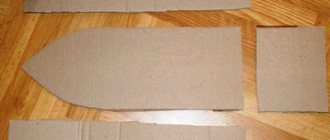
A case where you can place an Arduino board, it can be a black box, which can be ordered from the link below.
Or take the same one as mine, from an old garland, everything fits there.
Operating principle
The device will be assembled using Arduino and installed on the back of the monitor. To determine the direction we will use the accelerometer. In stationary mode, the accelerometer interprets gravity as an upward acceleration of 9.8 m/s2. The accelerometer will communicate with the Arduino via the I2C interface. The Arduino will constantly monitor (interrogate) which direction the accelerometer thinks it is accelerating. When changed, the Arduino will send a signal to the computer via USB. A python script running on the computer will read this change and tell the computer to rotate the display in the appropriate direction.
Rotary device layout
This article explains how to implement this on Windows and Linux. This can probably be done on a Mac as well. However, since I don't have a Mac, I can't try. The only difference is the system command called by the Python script.
Explanations for the code
Understanding the details of the I2C interface is not necessary for this project. But if you want to know more about it, then check out our article “I2C Bus. Basic concepts".
Let's look at MMA7455.h.
typedef enum {Y_POS, Y_NEG, X_POS, X_NEG, Z_POS, Z_NEG, NOT_SURE} orientation;
Enum in C is a data type like int or char. It is used for variables that can definitely be one of the values from a short list of non-numeric variables. In this case, we use enum to store the device orientation in a variable.
Look at the accelerometer. You will see x and y arrows on it. When the x arrow points to the top, then we must specify X_POS. When the x arrow points down, we must indicate X_NEG. The z axis points towards the board. When the board is lying on the table in a horizontal position, this state is designated Z_POS.
When installed on the back of a monitor, the device should always have the x-axis or y-axis facing up or down. In monitor.ino we created a macro called VALID_ORIENTATION to check if a given orientation matches one of 4 possible options. As you can see, we can check the value of an enumeration just like the values of any other data type.
#define VALID_ORIENTATION(o) ((o==Y_POS) || (o==Y_NEG) || (o==X_POS) || (o==X_NEG))
The setup() function is mainly diagnostic. There are three important lines in it:
Serial.begin(9600);
The line above initializes communication on the serial port through which we will interact with the computer.
Wire.begin();
Initializes communication via the I2C bus, through which we will interact with the accelerometer. It initializes settings only on the Arduino side. We initialize the accelerometer using the following line:
error = MMA7455_init(START_ORIENTATION);
When you press the button, its contacts do not close perfectly. They "chatter" and the signal appears as if the user pressed the button several times within a few milliseconds. We wait 100ms to make sure our code doesn't interpret the bounce as a sequence of clicks. There are two approaches to combat contact bounce. We can implement either hardware or software contact debouncing. The hardware method involves adding a low-pass filter, either active or passive, to the circuit. Since this involves purchasing and soldering additional components, I opted for software debouncer instead.
The accelerometer we use has some interrupt functions, but in our case they are not applicable. That's why we resorted to polling (interrupts are preferable from a performance perspective). As a general rule, it is recommended to use interrupts when working with buttons. However, since we are already polling the accelerometer, we can also poll the button at the same time.
Each time in the loop we check to see if the button is currently pressed. If so, and it was not pressed the previous time, then we know that the user just pressed it, and so we run the setup() function again and send START_ORIENTATION to the computer. We then wait 100ms before continuing. This delay is to allow the Arduino to wait for the pins to reach their final state before continuing. Admittedly, this is a rather sloppy and lazy approach to software debouncing because the Arduino doesn't do anything during the delay. A more complex approach would include timers so that while the Arduino waits for the pins to settle, other code can execute. In this particular case, the only thing we're missing out on by using a delay instead of a timer is changing the accelerometer readings. Since this shouldn't happen when the user presses the button, this sloppy method can be considered acceptable. The only advantage of the delay method is its simplicity. Hardware debouncing requires additional components, and writing code for interrupts and delays can be complex.
}else if(!digitalRead(BUTTON_PIN) // the button was pressed && previous_button_state) // and this is the first time it was pressed { // send even if the orientation was changed setup(); // recalibrate sendOrientation(START_ORIENTATION); delay(100); //software contact debouncing previous_button_state = 0; }
The principle of operation of a transistor for smooth control of an LED strip
A transistor works like a water faucet, only for electrons. The higher the voltage applied to the base of the bipolar transistor or the drain of the field effect transistor, the lower the resistance in the emitter-collector circuit, the higher the current passing through the load.
Having connected the transistor to the Arduino analog port, we assign it a value from 0 to 255, and change the voltage supplied to the collector or drain from 0 to 5V. The collector-emitter circuit will pass from 0 to 100% of the load reference voltage.
To control an Arduino LED strip, you need to select a transistor of suitable power. The operating current for powering the LED meter is 300-500mA; a power bipolar transistor is suitable for these purposes. For longer lengths, a field effect transistor will be required.
Connection diagram for LED strip to Arduino:
This is interesting: Choosing ceiling chandeliers with a fan