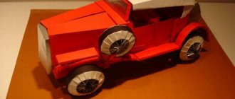
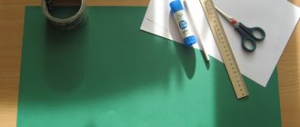
Paper crafts are an interesting and simple activity for children. Here we will look at how to make a paper car with your own hands. Surely you already have all the materials necessary for the work. Origami paper, glue and scissors for crafts are almost all the tools.
If you've never made a paper machine , you should probably start with a very simple design that uses straight lines. The article presents many options, from the simplest paper cars to three-dimensional 3D models and origami racing cars . Although younger children may need your help, don't limit their imagination. Let them surprise you with their creativity again and again.
Setting up the RTC board server
All settings of the control board can be edited in a special control panel for the control board (not to be confused with the Virturilka admin panel). This is what the control panel looks like now (first version)
In the “General Settings” tab, you can set the device name (displayed when the device is detected in applications), specify whether the controller server should be launched automatically when loading Virturilka, and set the configuration type.
The configuration can be local (i.e., the configuration file is permanently located in the controller directory and is available for editing in the control panel), or it can be remote, when the configuration file is downloaded every time the controller is launched from the web server.
Remote config server, by default, https://rc.virt2real.ru/getconfig; only registered users of the forum forum.virt2real.ru are allowed to create and edit configurations there
In the topic I will only talk about the local configuration; you can try the remote configuration yourself if anyone is interested. By the way, when I was driving around Shenzhen (video at the end of the topic), I used the remote config so that I could change the settings. Changing settings from the application is still in the form of sketches, it doesn’t really work yet, but even when I finish it, the remote config will still be useful.
So, what interests us most now is the “Local Configuration” tab. In general, the default config already configures the control board in server mode, you can connect the machine and control it locally (on a local network, from a Windows application, from an Android or from an iPhone/iPad). Unless you may need to swap channels. But for P2P (peer-to-peer) mode, for control via the Internet, the settings will have to be changed.
By default, the universal.so library is responsible for all control, the parameters for which are located at the end of the config, in the “[universal]” section.
The correspondence between control channels and PWM/PPM channels is specified by the axis parameter.
axis=0,1,2,3
By default, 4 PPM channels are configured, which are located on pins CON43, CON44, CON19, CON42. These config lines are responsible for this:
ch0=43,ppm,500,1500,2500,127,0 ch1=44,ppm,500,1500,2500,127,0 ch2=19,ppm,500,1500,2500,127,1 ch3=42,ppm ,500,1500,2500,127,1
The channel setting format is: chX=CON,TYPE,MIN,CENTER,MAX,NEUTRAL,NOAUTOCENTER
Where X
— PWM/PPM channel number, from 0 to 3
CON
— pin number (not GPIO, but pin, see diagram)
TYPE
— signal type, ppm or pwm.
For the typewriter you need ppm, for the pwm type there is a different format for the config line. MIN
— minimum position of the PPM signal, in milliseconds.
MAX
— maximum position of the PPM signal, in milliseconds.
CENTER
— central position of the PPM signal, in milliseconds.
NEUTRAL
- relative neutral value, i.e.
neutral meaning of control commands. Usually = 127 NOAUTOCENTER
- if = 0 - automatically return the signal to the central position, = 1 - do not return. For the gas and steering channels of the car you need to specify 0, for the servo channels that are used to rotate the view camera - you need to specify 1 (if there are any, of course)
If your car has headlights, you can turn them on and off; you will need to assemble a simple transistor amplifier (one field-effect transistor, essentially). To receive a control signal, the “pins” parameter is used. It specifies pins that will be set to 0 or 1 when a button is pressed in Virt2real Player (on the on-screen buttons, on the keyboard, with the mouse or on the gamepad).
pins=1.30,0.0|2.31,0.1
The format is: pins=CHANNEL,CON,DEFVALUE,SAVESTATE|...
where
CHANNEL
is the button channel (from 1 to 32)
CON
is the pin number that needs to be set to 0 or 1 upon receipt of a control command from the buttons
DEFVALUE
is the value to which the given the pin will be set when starting the
SAVESTATE
control board - if = 0 - when the button is pressed, set the pin to 1, when released - set to 0. If = 1 - when the button is pressed, set the pin to 1, when the button is released, do nothing. The next time you press the button, set the pin to 0, and when you release it, do nothing again. And so on in a cycle.
Button channels can be specified in a row using the “|” separator.
A short conclusion from this vague information - if you have the gas and steering channels mixed up, you can swap them by changing the axis parameter to axis=1,0,2,3 
If you need to limit the extreme position of the steering servo, change the MIN and MAX values for the desired channel. If the car moves forward or backward in the neutral position, change the CENTER value for the desired channel.
In the “Additional modules” tab there is a list of active and inactive controller modules.
A module is a separate application (an executable binary) that usually acts as a telemetry source. Active modules are those that start automatically when the controller starts and end when it shuts down. In the control panel, you can move modules from one column to another by clicking on the orange arrow. When you move to the active column, the module starts immediately, no matter whether the controller is running or not. When moving to inactive, the module automatically stops working.
The modules work simply - they read the required parameters and send them via UDP to the local port (ext_telemetry) specified in the config. And there the control board already receives the information and transmits it via the telemetry channel to the Virt2real Player application. At the same time, the same information is transferred to the user library of the device (in our case it is universal.so) so that the application can analyze the information and use it for its intended purpose. For example, I had a library of devices called autobot.so - a controlled cart that, in addition to being controlled by the user, could also drive autonomously, guided by a signal from an ultrasonic rangefinder.
Among the main modules, statuswifi supplies information about the status of the Wi-Fi link to the control board. Airosstatus.php (yes, the module can be written manually) - reads the status of the link from Ubiquity equipment, gps - reads the GPS receiver. The imu module processes information from inertial sensors (forms Euler angles, azimuth and compass), although it currently only works with one type of sensor, so it is not yet suitable for universal use. Nfc - reads NFC tags, but also works only with one type of reader. rc.in - reads PPM signals from the RC receiver, i.e. The machine can also be controlled from a regular app; it has priority over control commands via Wi-Fi. rfid - reads RFID tags. statusyota - reads the status of the 4G link of the Yota modem. usrange - reads ultrasonic rangefinder readings. voltage — determines the board’s supply voltage; a simple voltage divider (2 resistors) is required to be connected to ADC0. In general, there are a lot of interesting modules, each requires a detailed description, so for now we consider that I mentioned them as a starting point
For our recipe for a controlled machine, the statuswifi module is relevant - if we are setting up a connection via Wi-Fi or statusyota - if we are connecting Virturilka via the Yota whistle.
In the Android and iPad/iPhone applications, the settings are simple; they only involve selecting control channels. In Android there is also a choice of button channel (by default the channel is not specified, the buttons are not displayed). But in the Windows application I’ve added so many features that I myself go into a state of slight panic when I realize that all this needs to be documented. For now I can only give a link to the description of the previous version of the application https://wiki.virt2real.ru/wiki/How_to_make_a controlled_cart_2 https://wiki.virt2real.ru/wiki/RCboard
The control protocol has changed noticeably since then, but the settings for the Windows application have not changed much, so it may help when fiddling around. I’ll try to write a detailed description of the current version next year.
By the way, in the earliest version I used the MAVLINK protocol to transmit telemetry, but as the features grew, it became insufficient, so I switched to my own protocol. And I’m thinking of adding MAVLINK as a parallel telemetry channel, but this will already be in the next version of the application.
I’ll just say one thing - it’s best to control the machine from a USB steering wheel and pedals connected to a computer. Well, or at least with an RC app connected with a trainer connector to the computer. And it may be cool to use your fingers on the smartphone screen, but it’s not convenient at all without tactile sensations.
Papercraft machines
Boys often have a desire to design cars using papercraft techniques. This is a technique in which blank parts are cut out according to a ready-made template. But it is not always possible to purchase a book from which car elements are cut out and glued together.
Don’t be upset because modern technologies, such as the Internet, make it possible to find options for cars, transfer the image to paper and make yourself a car. Many people are interested in how to make a toy out of paper using the papercraft technique without having special books with details? Yes, everything is simple here.
The first thing you need to do is find and print a drawing of the car. This could be a sports car, a racing car, special construction equipment and many other options.
The assembly diagram is carried out according to the layout, but in order for the design to turn out correctly, you have the task of cutting out all the parts evenly from the printed image. After printing, you should pay attention that the white elements are the junction points of the parts. Glue is applied to them and the parts are fixed together.
(2)
It is recommended to choose glue for this type of activity, one that does not leave marks, but holds the paper well.
For kids, such a hobby is very interesting; it can captivate him for many years, while he will collect more and more new car models. And who knows, maybe after growing up, childhood fun, he will be attracted to a similar type of activity in the field of mechanical engineering.
Master class “Fun Truck”
Give your child paper or napkins of different colors and let them tear them into small pieces.
Print out the outline of the “Fun Truck” car on cardboard and cover it thickly with PVA glue. Together with your child, randomly scribble pieces of paper onto the outline.
Brush off excess parts. The work is ready
What you will need for assembly
- Machine with motor governor, motor and servo
- Battery (any with a voltage suitable for the regulator)
- Virt2real controller (Virturilka) with camera, USB-OTG adapter, micro-SD flash drive
- Whistle Wi-Fi or Yota (any other 4G modem is also possible)
- Hands of moderate linearity
But first, to demonstrate some use cases
As I already wrote, we have already used the rtsboard in many places, but from the documented cases I found only these:
Testing of a radio board on a buggy in Shenzhen, controlled from Moscow
Testing the digital board on a crawler in St. Petersburg, controlled from Moscow
habrahabr.ru/company/virt2real/blog/223145
Testing the control board on an airplane over St. Petersburg, controlled from Moscow
habrahabr.ru/company/virt2real/blog/223183
Cool snow blower controlled by a control board
By the way, the snow blower itself is the development of Perm guys https://omiplow.ru
The heaviest device controlled by a control board
Joint project with the Open Research Center for Advanced Technologies
Truck
Let us immediately note that a cardboard truck will look more interesting if it is made voluminous.
To make a truck, prepare:
- cardboard or thick paper;
- scissors and glue;
- wooden skewers for canapés;
- double-sided adhesive tape;
- plastic containers;
- compass and pin.
Having collected the entire list of materials and tools, we begin manufacturing:
- We take thick paper or cardboard, cut out 4 squares from it to construct the cabin, 3 identical rectangles and 2 squares to make the body. We put the cut out elements into 2 boxes and fasten them with tape.
- We take the squares that are intended for the cabin and cut out holes in them for the front and side glass. Now we cut out pieces from a plastic bottle and fix them with tape in the cut out areas.
- We glue the cabin and body into a single piece.
We've figured out how to make a car body out of paper, now let's start making wheels. To do this, you need to take black colored cardboard and use a compass to mark eight identical circles. We cut out the circles, and to make them more stable, glue them in pairs. In the middle of each wheel, you need to make holes using a pin.
Similar holes are made in the body and cabin. We insert wooden skewers and put wheels on them.
Upon completion of production, you can paint the craft. If it is necessary for the truck to be more stable, instead of 2 circles, glue 4. If you want your child to learn how to make a truck out of cardboard, you can involve him in the work during production. It’s interesting for you and exciting for your child to participate in the construction of his toy.
Sport Car
Previously, we told you how to make a simple car out of paper, now we will complicate the work and make a racing car. This toy is capable of moving, for which it is enough to place the craft on a slippery and flat surface and blow on it. To make such a model, you only need office paper.
Manufacturing process:
- take a sheet and fold it in half, but not across, but lengthwise;
- we apply the corners located at the top and bottom on the right and left in the middle;
- iron everything well;
- now we form the bend of the upper side with internal triangles according to class=”aligncenter” width=”1024″ height=”680″[/img] (Step 2)
- We bend the already formed triangles to the middle of the workpiece;
- then bend the side parts inward towards the center;
- fold the bottom side of the triangle onto the top of the workpiece and bend the product in half;
- We bend the remaining corners into the resulting pockets.
The car is basically ready, you can paint it if you wish.