Eccentric clamp
Easy to manufacture, with a high gain, a fairly compact eccentric clamp, which is a type of cam mechanisms, has another, undoubtedly, main advantage.
. – instantaneous performance. If in order to “turn on and off” a screw clamp it is often necessary to make at least a couple of turns in one direction and then in the other, then when using an eccentric clamp it is enough to turn the handle only a quarter turn. Of course, in terms of clamping force and working stroke, screw mechanisms are superior to eccentric ones, but with a constant thickness of the parts being fixed in mass production, the use of eccentrics is extremely convenient and effective. The widespread use of eccentric clamps, for example, in stocks for assembling and welding small-sized metal structures and elements of non-standard equipment, significantly increases labor productivity. The working surface of the cam is most often made in the form of a cylinder with a circle or Archimedes spiral at the base. Later in the article we will talk about the more common and more technologically advanced round eccentric clamp.
The dimensions of eccentric round cams for machine tools are standardized in GOST 9061-68*. The eccentricity of the round cams in this document is set to 1/20 of the outer diameter to ensure self-braking conditions over the entire operating range of rotation angles at a friction coefficient of 0.1 or more.
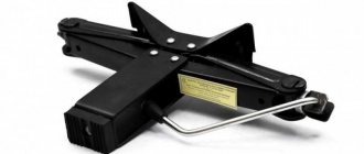
How to make a powerful clamp with a quick clamp
A clamp is a fastening device used to hold and secure objects tightly together to prevent any movement when internal pressure is applied. There are many types of clamps available on the market for many different purposes. Some are temporary, used to hold components while securing them together, while others are intended for permanent use.
Calculation in Excel of an eccentric clamp.
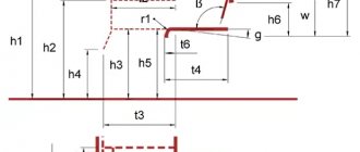
The figure below shows the geometric diagram of the clamping mechanism. The fixed part is pressed against the supporting surface as a result of turning the eccentric handle counterclockwise around an axis rigidly fixed relative to the support.
Program in MS Excel:
In the example shown in the screenshot, based on the given dimensions of the eccentric and the force applied to the handle, the mounting size from the axis of rotation of the cam to the supporting surface is determined, taking into account the thickness of the part, the self-braking condition is checked, the clamping force and the force transfer coefficient are calculated.
The value of the friction coefficient “part - eccentric” corresponds to the case “steel on steel without lubrication”. The value of the friction coefficient “axle - eccentric” is selected for the “steel on steel with lubrication” option. Reducing friction in both places increases the power efficiency of the mechanism, but reducing friction in the area of contact between the part and the cam leads to the disappearance of self-braking.
Algorithm:
9. φ 1 =arctg ( f1 )
10. φ 2 =arctg ( f2 )
11. α =arctg (2* e / D)
12. R = D/ (2*cos ( α ))
13. A = s + R *cos ( α )
14. e ≤ R * f1 + ( d /2) * f2
If the condition is met, self-braking is ensured.
15. F = P * L * cos ( α )/( R * tan ( α + φ1 )+( d /2)* tan ( φ2 ))
16 . _ k = F/P
If, based on a given clamping force or force transfer coefficient, it is necessary to determine the dimensions of the eccentric, then this inverse problem can be easily solved using the Excel “Parameter Selection” service. What it is and how to use this service is described in detail and shown in the video at the end of the article about the heat exchanger.
Eccentric clamp
The eccentric clamp is an improved design clamping element. Eccentric clamps (ECC) are used for direct clamping of workpieces and in complex clamping systems.
The above considerations force, where possible, to replace manual screw clamps with quick-release clamps.
Although the eccentric clamp is fast, it does not provide high clamping force on the part, so it is used only for relatively small cutting forces.
Advantages:
Flaws:
Eccentric Clamp Design
Round eccentric 1, which is a disk with a hole offset relative to its center, is shown in Fig. 113, a. The eccentric is freely mounted on axis 2 and can rotate around it. The distance e between the center C of disk 1 and the center O of the axis is called eccentricity.
A handle 3 is attached to the eccentric, by turning which the part is clamped at point A (Fig. 113, b). From this figure it can be seen that the eccentric works like a curved wedge (see shaded area). To prevent the eccentrics from moving away after clamping, they must be self-braking. The self-braking property of eccentrics is ensured by the correct choice of the ratio of the diameter D of the eccentric to its eccentricity e. The ratio D/e is called the eccentric characteristic.
Thus, all eccentric clamps, whose diameter D is 14 times greater than the eccentricity e, have the property of self-braking, i.e., they provide reliable clamping.
Eccentric clamping mechanisms include eccentric cams, supports for them, trunnions, handles and other elements. There are three types of eccentric cams: round with a cylindrical working surface; curved, the working surfaces of which are outlined along an Archimedes spiral (less often - along an involute or logarithmic spiral); end
Round eccentrics
Due to ease of manufacture, round eccentrics are most widespread.
A round eccentric (in accordance with Figure 5.5a) is a disk or roller rotated around an axis displaced relative to the geometric axis of the eccentric by an amount A, called eccentricity.
Curvilinear eccentric cams (in accordance with Figure 5.5b) compared to round ones provide stable clamping force and a larger (up to 150°) rotation angle.
Cam materials
Eccentric cams are made of steel 20X, carburized to a depth of 0.8...1.2 mm and hardened to a hardness of HRCe 55-61.
Types of eccentric clamps
Eccentric cams are distinguished by the following designs: round eccentric (GOST 9061-68), eccentric (GOST 12189-66), double eccentric (GOST 12190-66), eccentric forked (GOST 12191-66), eccentric double-bearing (GOST 12468-67) .
The practical use of eccentric mechanisms in various clamping devices is shown in Figure 5.7
Calculation of eccentric clamps
The initial data for determining the geometric parameters of the eccentrics are: tolerance δ of the size of the workpiece from its mounting base to the place where the clamping force is applied; angle a of rotation of the eccentric from the zero (initial) position; required force FZ of clamping the part. The main design parameters of eccentrics are: eccentricity A; diameter dc and width b of the eccentric pin (axis); eccentric outer diameter D; width of the working part of the eccentric B.
Calculations of eccentric clamping mechanisms are performed in the following sequence:
Calculation of clamps with a standard eccentric round cam (GOST 9061-68)
1. Determine the stroke hk of the eccentric cam, mm:
If the rotation angle of the eccentric cam is not limited (a ≤ 130°), then
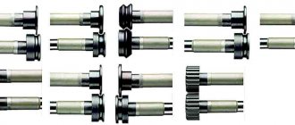
§ 4. Assembling the eccentric mechanism
The eccentric mechanism serves to convert rotational motion into reciprocating motion. It is used in machine tools, stamping presses, and in the spool and valve distribution of machine engines. An eccentric mechanism is a type of crank mechanism with a small crank radius.
The eccentric mechanism is shown in Fig. 91. The detachable eccentric mechanism (Fig. 91, a) has a round disk (eccentric) 2, sitting on a key 8 and on a shaft 3. The axes of the shaft and the disk should not coincide. The distance between the axles (eccentricity) is the radius of the crank. The disk is covered by a detachable clamp 1, fastened with bolts 4. A connecting rod 7 (and rod 6) is connected to the clamp, the fork of which, through pin 5, is pivotally connected to a slider that receives reciprocating motion (for example, with a press slider or with a distribution spool).
Rice. 91. Eccentrics: a - with a detachable clamp, b - with a mechanism for adjusting the eccentricity
The eccentric mechanism can have two eccentrics (Fig. 91, b). The internal eccentric 2 sits on the shaft 3 and is covered by the external eccentric 9. The latter can be rotated and secured in various positions, which leads to a change in eccentricity, and therefore a change in the stroke length of the slider. An eccentric mechanism is used in spool-type steam distributors and oil engine regulators. Eccentrics are made of cast iron or carbon steel. The inner surface of the clamp is filled with babbitt.
Assembly and adjustment of the eccentric mechanism usually begins with seating the eccentric on the shaft. The eccentric is secured to the shaft with a key. The assembled shaft is installed in bearings, after which a clamp is put on the eccentric and secured with bolts. First, the lower half of the clamp is connected to the connecting rod.
Adjust the gap between the eccentric and the clamp using spacers installed between the clamp’s connector planes. As the working surface of the clamp wears out during operation of the eccentric, these spacers are gradually removed.
After assembling and adjusting the eccentric, connect the connecting rod forks to the slider. The connecting rod is adjusted only in length using a coupling nut 6 (Fig. 91, a). This adjustment is necessary to set the end positions of the slider stroke.
Of the control operations when assembling eccentrics, the most important is to check that the eccentric shaft axis is perpendicular to the slider guides. If there are distortions, this will lead to increased wear of the slider guides and the working surfaces of the eccentric and clamp
Introduction
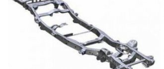
The machine consists of three main structural elements:
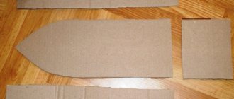
The base and the sawing table itself are not very complex structural elements. Their design is obvious and not so complicated. Therefore, in this article we will consider the most complex element - the parallel stop.
So, the rip fence is a moving part of the machine, which is a guide for the workpiece and it is along it that the workpiece moves. Accordingly, the quality of the cut depends on the parallel stop because if the stop is not parallel, then either the workpiece or the saw blade may become jammed.
In addition, the parallel stop of a circular saw must be of a rather rigid structure, since the master makes efforts to press the workpiece against the stop, and if the stop is displaced, this will lead to non-parallelism with the consequences indicated above.
There are various designs of parallel stops depending on the methods of attaching it to the circular table. Here is a table with the characteristics of these options.
| Rip fence design | Advantages and disadvantages |
| Two-point mounting (front and rear) | Advantages: · Quite rigid design, · Allows you to place the stop anywhere on the circular table (to the left or right of the saw blade); · Does not require the massiveness of the guide itself. Disadvantage: · For fastening, the master needs to clamp one end in front of the machine, and also go around the machine and secure the opposite end of the stop. This is very inconvenient when selecting the required position of the stop and with frequent readjustment it is a significant drawback. |
| Single point mounting (front) | Advantages: · Less rigid design than when attaching the stop at two points, · Allows you to place the stop anywhere on the circular table (to the left or right of the saw blade); · To change the position of the stop, it is enough to fix it on one side of the machine, where the master is located during the sawing process. Disadvantage: · The design of the stop must be massive in order to ensure the necessary rigidity of the structure. |
| Fastening in the groove of a circular table | Advantages: · Quick changeover. Disadvantages: · Complexity of design, · Weakening of the circular table structure, · Fixed position from the line of the saw blade, · Quite a complex design for self-production, especially from wood (made only from metal). |
In this article we will examine the option of creating a parallel stop design for a circular saw with one attachment point.
Do-it-yourself eccentric for a vibrating plate - Metalworker's Guide
Home craftsmen perform construction work as economically as possible. In this case, a pre-assembled homemade tool helps. Components for it are usually selected from available materials.
Recently, a do-it-yourself vibrating plate with an electric motor has been in demand. It is used for laying paving slabs, compacting fine soil, and during the process of laying the foundation.
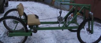
How to make a vibrating plate with a gasoline engine with your own hands
When performing various types of construction and landscaping work, it is always necessary to compact the soil, for which specialized powerful equipment is used.
A self-made vibrating plate will allow you to save on the purchase of professional equipment, while such units are distinguished by their ease of execution, quality, reliability and functionality.
Eccentric clamps
Eccentric clamps . For large production programs, quick-release clamps are widely used. One type of such manual clamps is eccentric, in which clamping forces are created by turning the eccentrics.
Significant forces with a small contact area of the working surface of the eccentric can cause damage to the surface of the part. Therefore, usually the eccentric acts on the part through the lining, pushers, levers or rods.
Clamping eccentrics can have different working surface profiles: in the form of a circle (round eccentrics) and with a spiral profile (in the form of a logarithmic or Archimedean spiral).
A round eccentric is a cylinder (roller or cam), the axis of which is located eccentrically with respect to the axis of rotation (Fig. 176, a, b). Such eccentrics are the easiest to manufacture. A handle is used to turn the eccentric. Eccentric clamps are often made in the form of crank shafts with one or two supports.
Eccentric clamps are always manual, so the main condition for their correct operation is maintaining the angular position of the eccentric after it is rotated for clamping - “self-braking of the eccentric.” This property of the eccentric is determined by the ratio of the diameter O of the cylindrical working surface to the eccentricity e. This ratio is called the eccentric characteristic. At a certain ratio, the condition for self-braking of the eccentric is satisfied.
Typically, the diameter B of a round eccentric is set for design reasons, and the eccentricity e is calculated based on the self-braking conditions.
The line of symmetry of the eccentric divides it into two parts. You can imagine two wedges, one of which secures the part when turning the eccentric. The position of the eccentric when it comes into contact with the surface of a minimum size part.
Design of a circular saw stop
The entire structure consists of two main parts - longitudinal and transverse (meaning relative to the plane of the saw blade). Each of these parts is rigidly connected to the other and is a complex structure that includes a set of parts.
The pressing force is large enough to ensure the strength of the structure and securely fix the entire rip fence.
From a different angle.
The general composition of all parts is as follows:
- The base of the transverse part;
- Longitudinal part
- , 2 pcs.);
- The base of the longitudinal part;
- Clamp
- Eccentric handle
Preparing for work
Before you begin, you need to decide on the necessary set of tools and materials that will be needed during the work process.
The following tools will be used for work:
During the work you will also need the following materials:
Let's look at eccentric clamps. An eccentric is a connection in one part of two elements - a round disk of radius r (Figure 2.39 - Eccentric) and a flat single-bevel wedge. When the eccentric rotates around the axis of rotation of the disk 0, the wedge enters the gap between the disk and the workpiece and develops a clamping force Q.
Figure 2.39 – Eccentric
The working surface of the eccentrics can be a circle (circular) or a spiral (curvilinear). Their difference lies in the fact that in the development of circular eccentrics the flat wedge turns out to be curvilinear with a variable angle α depending on the angle of rotation β (Figure 2.39, b - Eccentric), and for curved eccentrics α does not depend on β. This means that curved eccentrics create a stable clamping force in a batch of workpieces, while circular eccentrics do not. When clamping with circular eccentrics, depending on the fluctuation in the size of the NTn in a batch of workpieces, the working angle of rotation β changes, and, consequently, the angle α and the clamping force Q. At the same time, the manufacturing technology of circular eccentrics is much simpler than curved ones. Therefore, circular eccentrics with an angle β=30÷135° are widely used to reduce vibrations of Q1 in a batch.
Figure 2.40 — Diagram of a clamping mechanism with an end cam
Cam clamps are the fastest acting of all manual clamping mechanisms. In terms of speed, they are comparable to pneumatic clamps.
The disadvantages of eccentric clamps are: small amount of working stroke, limited by the amount of working stroke, limited by the amount of eccentricity; increased fatigue of the worker, since when unfastening the workpiece the worker must apply force due to the self-braking property of the eccentric; unreliability of the clamp when the tool operates with shocks or vibrations due to the danger of self-detachment.
Despite these disadvantages, eccentric clamps are widely used in fixtures, especially for small-scale and mass production.
When designing an eccentric clamp, it is necessary to determine its design and dimensional parameters based on the clamping force Q required to secure the workpiece. The initial data for the calculation are: Tn – tolerance for the size H of the workpiece from the base to the point of application of the clamping force; β – working angle of rotation of the eccentric from the zero (initial) position; Q is the force required to secure the workpiece. The result of the calculation should be: e - eccentricity of the eccentric, d - diameter of the trunnion, R - radius of the working surface of the eccentric, B - width of the working surface, l - length of the handle (with manual clamping).
At angle β
How disc brakes work
Brake mechanism with floating caliper.
1 — brake disc; 2 — brake pads; 3 - piston; 4 - working brake cylinder (caliper) The disc brake mechanism, like any other brake, is designed to change the speed of the vehicle.
Step-by-step diagram of how disc brakes work:
- When the driver presses the brake pedal, it creates pressure in the brake pipes.
- For a fixed caliper mechanism: fluid pressure acts on the pistons of the brake wheel cylinders on both sides of the brake disc, which in turn press the pads against it. For a floating caliper mechanism: fluid pressure acts on the piston and caliper body simultaneously, causing the latter to move and press the pad against the disc on the other side.
- A disc sandwiched between two pads reduces speed due to friction. And this, in turn, leads to braking of the car.
- After the driver releases the brake pedal, the pressure disappears. The piston returns to its original position due to the elastic properties of the sealing lip, and the pads are retracted using slight vibration of the disc during movement.
Eccentric coupler: types, application features and mounting options
The requirements for furniture fasteners are as follows: 1. The fasteners must provide the necessary strength and, no less important, the accuracy of the connection. 2. Be inconspicuous or at least aesthetically attractive. 3. Additive (drilling holes for installing fasteners) should be simple and take as little time as possible. The fewer holes, the better. 4. Furniture assembly should be simple and convenient. 5. The connection should be cheap (you need to consider not only the cost of the fittings, but also the man-hours and machine-hours spent on both the additive and the assembly of the furniture). Often, the use of more expensive fittings can significantly reduce the cost of furniture as a whole + increase its consumer properties (quality) Notes on the topic: Unfortunately, neither “confirmat” nor eccentric ties such as “Minifix” or “Rafix” are self-sufficient, since they do not provide centering of furniture blanks and require the installation of centering dowels nearby. It seems to me that the manufacturers of these eccentric couplers deliberately make them this way, without relying on the accuracy of the additive. Therefore, if we count the holes required for the additive, then 4 holes require (two each in the face and end) require confirmations, 4 holes require Rafix type ties (3 in the face and 1 in the end) and 5 holes require “Minifixes” (3 in end and 2 in face). This is bad. In addition, you can count how many parts a connection consists of using a “minifix”: dowel, liner, rod, eccentric, plug. Even if you do without the futurka, you still get three elements. Therefore, all of the above options for fittings should be considered as something not exactly cheap, but labor-intensive and complex for “garage workers.” Is there anything without the listed disadvantages? The answer is yes. Eat. Some are presented in Russia. Such accessories are not produced in Russia, but are imported. There are different options. They require drilling not 4 or 5 holes, but only 2 (only in the face or in the face and in the end) or 3 (2 in the face, one in the end), and consist of only 1 or 2 elements (maximum). The time for assembling furniture is reduced by 2-5 times. Production time is reduced in proportion to the reduction in quantity, as well as movement from one production site to another. There are options for fittings that have never been imported to Russia. Including, for example, completely hidden ones. The disadvantages of such fittings are the following: it requires a more precise additive and is more expensive. And further. Few people know about such accessories. I have no connection with companies that supply such accessories and therefore there is no reason to advertise sellers and manufacturers of such accessories. Reply
What is a tool needed for, its design and types of tools
The clamp is an additional carpentry tool. The main purpose of clamps is to fix a workpiece on a support surface or several workpieces for gluing them together; therefore, the design of the tool must include at least two elements: a support surface and a movable jaw equipped with a fixation mechanism. The movable jaw is usually moved using a screw or lever, which allows for increased compression and prevents backlash during operation. Depending on the specialization and design features, the following types of clamps are distinguished:
- Screw G-shaped ones are the most common, characterized by their simple design and relatively low cost. They are represented by a metal bracket, on one side of which there is a supporting surface, and on the other - a threaded eyelet with an adjusting screw screwed into it. The inner part of the screw is equipped with a working jaw, the outer part with a handle. The tool is effective when working with heavy, large workpieces of simple shape.
Clamps of this type are suitable for working with large workpieces
Objects are fixed using an auxiliary screw and a stepper mechanism
The clamp is suitable for working with large workpieces
Clamps of this type simplify joining workpieces at right angles
Corner clamp with double-sided corner block
Making a circular saw
Preparation of blanks
A couple of points to note:
We drill a 22 mm hole in the end for the handle.
It is better to do this by drilling, but you can simply hammer it with a nail.
The circular saw used for work uses a homemade movable carriage made of (or, as an option, you can whip up a false table), which is not too bad to be deformed or damaged. We hammer a nail into this carriage in the marked place and bite off the head.
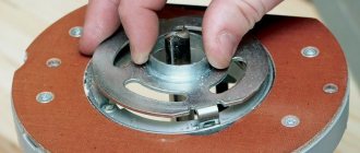
As a result, we get a smooth cylindrical workpiece that needs to be processed with a belt or eccentric sander.
We make a handle - it is a cylinder with a diameter of 22 mm and a length of 120-200 mm. Then we glue it into the eccentric.
Transverse part of the guide
Let's start making the transverse part of the guide. It consists, as mentioned above, of the following details:
Upper transverse clamping bar
Both clamping bars - upper and lower - have one end that is not straight 90º, but inclined (“oblique”) with an angle of 26.5º (to be precise, 63.5º). We have already observed these angles when cutting the workpieces.
The upper transverse clamping bar serves to move along the base and further fix the guide by pressing against the lower transverse clamping bar. It is assembled from two blanks.
Both clamping bars are ready. It is necessary to check the smoothness of the ride and remove all defects that interfere with smooth sliding; in addition, you need to check the tightness of the inclined edges; There should be no gaps or cracks.
With a tight fit, the strength of the connection (fixation of the guide) will be maximum.
Assembling the entire transverse part
Longitudinal part of the guide
The entire longitudinal part consists of:
This element is made from the fact that the surface is laminated and smoother - this reduces friction (improves sliding), and is also denser and stronger - more durable.
At the stage of forming the blanks, we have already sawed them to size, all that remains is to refine the edges. This is done using edge tape.
The edging technology is simple (you can even glue it with an iron!) and understandable.
The base of the longitudinal part
We also additionally fix it with self-tapping screws. Do not forget to maintain a 90º angle between the longitudinal and vertical elements.
Assembly of transverse and longitudinal parts.
It is important to maintain an angle of 90º, since the parallelism of the guide with the plane of the saw blade will depend on it.
Installation of the eccentric
Installing the guide
It's time to attach our entire structure to the circular saw. To do this, you need to attach the cross stop bar to the circular table. Fastening, as elsewhere, is carried out using glue and self-tapping screws.
... and we consider the work finished - the circular saw is ready with your own hands.
Let's start making a vice
Well, now let’s get to work so that the dream turns into reality. We find the rest of the useless channel, mark it with a ruler and marker and cut off the required piece using a grinder. It will become the basis for the movable and fixed jaws of our vice.
From a suitable equal angle corner after marking, we cut off two pieces of equal length, which in a vice will become the base of the jaws of our homemade vice.
In the middle of the shelf of one of the corners - the future movable jaw of the vice - we mark the center of the hole, which we drill on a drilling machine.
On the crosspiece of the channel blank, along its central axis, closer to one end, we mark the boundaries of the slot along which the movable jaw of our vice will move. Mark the marked points and drill holes, which will be the ends of the slot.
Using a grinder, we cut out a strip of metal in the channel bridge between these two holes and knock it out with the tapering head of a hammer. This slot will set the limits of movement of the movable jaw of the vice.
Using a grinder, we cut two pieces from a suitable metal strip, the length of which is equal to the width of the corner shelf. They will serve as limiters for the movable jaw as it moves along the slot.
Next, we connect the angle and channel using a bolt and nut in the position that they will occupy in the finished vice.
We clamp this structure in a bench vice and weld limiters to the corner transversely on both sides of the channel, holding them with pliers. To avoid accidentally welding them to the channel flanges, we place a thin piece of rubber, plastic or other dielectric material between them during welding.
Then, from a used hammer with a round head, we cut off a cylindrical blank with a grinder approximately equal in height to the diameter - the blank for the future eccentric clamp.
We mark a point at its end with some eccentricity - an indentation from the central longitudinal axis of the cylinder. Using the mark, we drill a through hole parallel to the axis of our workpiece.
From a thick strip of metal, after marking, we cut out two pieces of length and height equal to the shelf of the equal-flange angle. These are future jaw pads for quick-release vices.
We drill two holes in these pads in the center closer to the edges. We unfold them from the front side under the heads of the mounting screws. Using a grinder, we make a notch and clean them. We test the quality of fastening the linings to the corner flanges (jaws) with two bolts and nuts.
We weld one corner (fixed jaw) transversely to the channel web on the side opposite the slot. We reinstall the pads on the fixed and movable jaws and finally screw them in place, using a wrench and a screwdriver.
From fairly thick metal we cut out a strip equal in size to the length of the corner, and in width to the distance between the ends of the shelves diagonally. We also weld it to ensure the strength and rigidity of the fixed jaw.
Now we take a thicker strip of metal and drill a hole at one end and cut a thread in it using a tap. Then we cut off a piece from it with a threaded hole of a rectangular shape, slightly different from a square. This homemade rectangular nut will hold the eccentric on the movable jaw, and allow them to move along the channel web (guide) in one direction or another.
To prevent the nut from rotating under the channel jumper, we cut off and weld two limiting guide rods on both sides of it longitudinally along the entire slot with a small gap.
In the side of the eccentric, approximately in the middle of its height, we drill a blind hole and cut a thread in it for fastening the handle. We assemble the movable jaw of the vice with pre-welded stops, screwing the finished cover with notches to the corner with two bolts.
We find a piece of sheet iron of sufficient thickness to ensure rigidity. We mark on it the contours of an octagonal-shaped base with two marks for holes for fastening. Using a grinder we cut it out. We weld a channel (guide) with a fixed jaw to it. We process welds and surfaces with a grinder to remove rust, metal deposits, roughness and rounding of edges.
We seal the sponge overlay and the longitudinal slot with a margin on the sides with construction tape.
With their help, with one movement of the eccentric handle, you can secure any workpiece in them quickly, reliably and without unnecessary effort.
Video: installing a furniture eccentric coupler
Easy to manufacture, with a high gain, a fairly compact eccentric clamp, which is a type of cam mechanisms, has another, undoubtedly, main advantage...
... – instantaneous performance. If in order to “turn on and off” a screw clamp it is often necessary to make at least a couple of turns in one direction and then in the other, then when using an eccentric clamp it is enough to turn the handle only a quarter turn. Of course, they are superior to eccentric ones in terms of clamping force and working stroke, but with a constant thickness of the fastened parts in mass production, the use of eccentrics is extremely convenient and effective. The widespread use of eccentric clamps, for example, in stocks for assembling and welding small-sized metal structures and elements of non-standard equipment, significantly increases labor productivity.
The working surface of the cam is most often made in the form of a cylinder with a circle or Archimedes spiral at the base. Later in the article we will talk about the more common and more technologically advanced round eccentric clamp.
The dimensions of eccentric round cams for machine tools are standardized in GOST 9061-68*. The eccentricity of the round cams in this document is set to 1/20 of the outer diameter to ensure self-braking conditions over the entire operating range of rotation angles at a friction coefficient of 0.1 or more.
The figure below shows the geometric diagram of the clamping mechanism. The fixed part is pressed against the supporting surface as a result of turning the eccentric handle counterclockwise around an axis rigidly fixed relative to the support.
The position of the mechanism shown is characterized by the maximum possible angle α
, while the straight line passing through the axis of rotation and the center of the eccentric circle is perpendicular to the straight line drawn through the point of contact of the part with the cam and the center point of the outer circle.
If you turn the cam 90˚ clockwise relative to the position shown in the diagram, then a gap is formed between the part and the working surface of the eccentric equal in magnitude to the eccentricity e
. This clearance is necessary for free installation and removal of the part.
Program in MS Excel:
In the example shown in the screenshot, based on the given dimensions of the eccentric and the force applied to the handle, the mounting size from the axis of rotation of the cam to the supporting surface is determined, taking into account the thickness of the part, the self-braking condition is checked, the clamping force and the force transfer coefficient are calculated.
The value of the friction coefficient “part - eccentric” corresponds to the case “steel on steel without lubrication”. The value of the friction coefficient “axle - eccentric” is selected for the “steel on steel with lubrication” option. Reducing friction in both places increases the power efficiency of the mechanism, but reducing friction in the area of contact between the part and the cam leads to the disappearance of self-braking.
Source
Self-clamping clamp: how to have fun
zen.yandex.ru A tool for quickly fixing objects! From a steel strip 30 mm wide, we saw off two sections 100 mm long. At the end of one plate we place a steel square with a wall width of 10 mm. We outline the square with a felt-tip pen. We drill holes in the corners of the outlined square, then use a grinder to cut out straight walls - connecting the drilled holes to each other. As a result, we should get a square-shaped hole into which the tenth square will be inserted.
It is more convenient to saw through the straight walls of the hole with a mini drill with a cutting disc. Then finish it with a flat file.
We clamp the plate with a square hole in a vice (between the jaws of the vice you should clamp exactly the end of the plate in which the hole is).
Now, along the clamped edge of the plate (where the plate protrudes from the jaws of the vice), we bend the plate at a small angle - 10 - 15 degrees.
Insert a steel square into the hole in the plate.
Next, place a square vertically on the second plate (without a hole). In this case, the plates, the top bent and the bottom, should be one above the other.
We weld the square to the plate.
We weld an additional overlay cut from a strip of the same size as the plate itself onto the free end of the lower plate.
On another similar overlay, we install a bolt vertically in its center (with the head to the plate), and weld the bolt to the plate.
At the free end of the plate, which is bent at an angle and is the top one, we drill a hole with a diameter of 8 mm for a bolt welded with a head to the lining.
We put a compression spring on the bolt, insert the bolt into the drilled hole in the top plate, and screw on the wing nut.
The wing nut is needed for ease of adjustment - spring compression.
The tool is ready!
We ended up with a self-clamping clamp, which does not need to be tightened with a screw, like with conventional clamps.
We place the object to be fixed on the edge of the workbench and install a clamp on it.
Press on the top plate.
The plate with its curved end with a square hole moves downwards along the vertical square.
The second end of the plate with a plate, a bolt and a spring attached to it, on the contrary, pulls the plate upward.
Thus, the upper plate is engaged (locked) by a square hole, which is made to skew, on the surface of the square.
The fixed object is securely pressed against the workbench!
To release the object from the clamp (in our example it is a wooden block), just press the edge of the top plate again and lift the plate up square with your other hand.