To reliably receive digital terrestrial signals and display television channels, you need the right antenna. The best way is to buy a factory design with an amplifier. This way you will be able to catch up to 30 terrestrial channels of the DVB-T2 standard on the territory of the Russian Federation, even if the repeater is very remote.
An alternative is a homemade antenna. It is possible to produce more than 10 design options that can accept “digital”. One of the designs that provides a good signal is the Kharchenko antenna.
In the circle of radio amateurs it is also called “biquadrat” (double square), “eight”, “diamond-shaped”, “double diamond”, “double zigzag”, “zigzag”.
In order for the biquad to work at the highest level, you need to make an antenna in accordance with the wavelength that is transmitted by the digital repeater. Therefore, it is necessary to make small calculations, since the quality of DVB-T2 signal reception depends on this.
The concept of the Kharchenko antenna
This is a zigzag antenna that looks like two squares fastened together. Each vibrator angle is 90°.
Signal reception at a sufficient level is ensured due to the design, compliance with the values, and wire length. It is for this reason that it is important to calculate the antenna for digital terrestrial television as accurately as possible. It is necessary to calculate the length of the conductor.
The biquad antenna can be used not only for receiving digital TV, but also as an amplifier for other types of signals. You can calculate the design in such a way that it turns out to strengthen the signal of mobile communications, mobile Internet (3G, 4G), Wi-Fi signal. In each case, when calculating, you will need to substitute different values into the formula.
The diamond-shaped antenna, in addition to its wide range of applications, has the following advantages:
- high gain;
- wide scope of application (described in a paragraph earlier);
- broadband – capable of receiving meter and decimeter waves simultaneously, which means you can tune in to digital and analog channels at once;
- ease and low cost of production. Even a beginner can make a Kharchenko antenna with his own hands for digital TV. You just need to make a simple calculation for the specific needs, bend a piece of copper wire according to the template and connect the antenna cable to the structure.
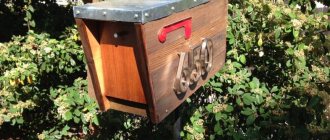
Antenna assembly for DVB-T2
Everything should be clear here. We take our segment VVG or whatever you have. To determine the approximate length of wire required to assemble the antenna, you can L1 * 8 and throw a couple of centimeters. 12*8+2=98 cm was needed to make my antenna.
If you have thick wire 4-5 mm in diameter, then most likely you will not be able to do without a vice. I had enough pliers.
We strip the wire from insulation. Then use pliers to bend the biquadrat. Let's look at the photos. All angles are 90 degrees.
Then we solder the 75 Ohm television cable. We solder the core to one square, the braid to another.
The signal at high frequencies propagates over the surface of the conductor, so it is better to paint the antenna after assembly. I used leftover acrylic exterior paint. It is better to fill the soldering area with hot glue or sealant.
We secure the wire from the soldering point with ties (straps) along the sides of the square, as in the photo. This mandatory action is antenna matching.
Making a biquad antenna with your own hands
The time required for assembling the structure is a maximum of 1 hour. If you know how to handle tools, and have at least some skill in assembling other structures, you can do it in 30-40 minutes. Elements for the structure can often be found at home. As a last resort, the components can be easily purchased at the radio market or at a hardware store.
Materials and tools
Main list:
- copper wire with a cross-section of 1.5-5 mm (it is better not to use an aluminum conductor or other material, since it is difficult to solder on them, and these places directly affect signal loss);
- coaxial cable with a resistance of 75 Ohms (for digital television broadcasting), 3-5 m long (depending on the location of the antenna, the further the installation is from the TV, the longer the cable will be);
- pliers to bend the wire in the right places if the material is thick and making bends with your hands is problematic;
- material for cleaning the places to which the cable will be connected (file or sandpaper);
- tape measure, centimeter or ruler to accurately measure the length of the element;
- soldering iron, materials for easy and high-quality soldering (rosin, tin);
- F-plug, which is mounted on the second end of the cable and inserted into the antenna connector of the TV.
If the antenna is installed on the roof of a private house, you may need a long wooden, plastic or even metal bar. It will serve as a matcha on which Kharchenko’s design will be fixed.
To protect connections when installed outside buildings, it is better to protect the antenna from moisture. The easiest way to wrap the joint and solder joints is with electrical tape. This option is simple, since the electrical tape can be torn off at any time and access to the connections. An option that will reliably close the connections (but tightly) is to fill them with epoxy resin, silicone sealant, hot melt adhesive or varnish.
Video
Manual calculation
You don’t have to calculate the antenna for T2, but then you are not sure that you will be able to watch digital channels at all. Therefore, you need to have accurate data; this will allow you to catch at least 20 channels in your region. Thirty channels (the third multiplex) can only be watched in Moscow, the region and Crimea.
Let's perform the calculation using the example of the city of St. Petersburg.
- First you should find out the frequencies of the channel numbers that are broadcast in the region. Since the biquad antenna must operate in both frequency ranges, you need to find out the channel frequency of the first and second multiplex. Based on the parameters of the repeaters on the TsETV map, the first multiplex (TVK 35) broadcasts at a frequency of 586 MHz, and the second operates at a frequency of 666 MHz (TVK 45).
Using the same map you can find out your frequencies yourself. Enter your exact address in the search bar and click on your home on the map.
- Determine the average value. This will make it possible to make the antenna in an intermediate design and catch the radio signal from both multiplexes at once. We calculate the arithmetic average: (586+666)/2=626 MHz. The value will be used in further calculations.
We calculate the length using the formula: λ = c/F, where
- λ is the desired wavelength;
- C – speed of light (3*108 m/s, which is equal to 300 s);
- F – average frequency determined earlier (626 MHz).
If we substitute the available values into the formula, we get the following:
λ = 300/626 ≈ 0.4792 m ≈ 47.92 cm.
This is a figure that is equal to the length of the copper conductor to make one diamond.
In practice, when making a “biquadrat”, such dimensions can become very large. It is allowed to take a smaller value, exactly two or four times.
We have:
- λ = 47.92 cm/2 = 23.96 cm;
- or λ = 47.92 cm/4 = 11.98 cm.
Now it’s worth calculating the length of each side of the rhombus. We will use the original value of 47.92 cm.
- This means that the side will be equal to L = 47.92/4 = 11.98 cm ≈ 12 cm.
- The total length required to bend the entire antenna (two diamonds) of wire is 47.92*2 = 95.84 cm ≈ 96 cm.
Kharchenko antenna calculator
Instead of manual calculations, you can find out the most accurate dimensions of a digital antenna using the online calculator below. All you need to do is enter the average frequency in the first field of the calculator. Next, click on the “Calculate” button and the calculator will immediately display the final parameters. The advantage of the calculator is that it performs a full calculation, and not just determining the size of the outer side of the vibrator.
All dimensions are indicated in millimeters. The required values are indicated on the left in the figure.
Manufacturing
- On the wire, starting at one end, make 8 equal marks with a marker, with the same distance between each. The distance is equal to the length of the side, calculated earlier - 12 cm.
The last mark can be made a little further (for example, 13 cm), exactly, as well as leaving 1 cm before the first mark. At the end and beginning of the conductor there will be a small “shoot” that can be bent. It will be easier to join and solder to it. You will see an example of the process in the third image below.
- Consistently bend the wire along the marks until you get a “double square”.
- If you previously left small “extra” sections of copper wire, then bend them down, perpendicular to the entire structure. Make sure that there is no short circuit between one corner and another.
- Carefully strip the free ends of the wire and the adjacent solid corner. Use sandpaper or a file. Connect the ends together by winding them with thin copper wire.
- Perform final fixation through soldering.
- Remove approximately 2 cm of the cable's top insulation. Twist the shielding layer. Also remove some of the inner insulation that covers the center copper core. If possible, also strip the cable core and shield to make soldering easier. Solder the core to one center corner and attach the shield to the other fold. Do not allow the bends to close, otherwise the biquad will not work.
To prevent the cable from wobbling, thereby “losing” the connection, secure it to one of the adjacent sides with a plastic clamp or electrical tape. The first option is preferable.
Cable fixation - Cover the soldered areas with insulating agent. For example, varnish, silicone, hot melt adhesive, epoxy. As a last resort, wrap it with electrical tape.
Execution options (photo)
Plug installation
The antenna is connected to the television receiver using an adapter (plug). The part is mounted on the second free end of the antenna wire.
The adapter consists of two parts - the connector itself and the plug. The latter must be unscrewed before installation on the cable, and then screwed back in.
- Remove 10-12 mm of the top PVC layer of the cable. Cut the material carefully so as not to cut the inner insulating layer.
- Bend the entire screen (braid with foil layer, if any) back.
- Strip the cable from the internal insulation until approximately 2 mm of material remains.
- Screw the F-connector onto the cable on top of the screen. It is necessary to screw in until a small part of the central insulation enters the connector and the cable core protrudes from the connector. If putting on the connector is difficult, you can carefully clamp the part with pliers and continue screwing. You should not squeeze the connector too hard, as often the metal is not of the best quality and can crack.
- Screw the F adapter into the connector and insert the cable into the antenna socket (“RF IN”, “ANT IN”) on the rear panel of the TV. If the TV is hung on the wall and there is practically no free space behind it, then it would be wiser to use a corner adapter rather than a straight one.
Connection
One end of the cable with a resistance of 50-75 Ohms is soldered to the finished antenna, the other to the plug. It is better to connect the cable to the upper part of the base, and use the lower part as fasteners.
The quality of image and sound during digital television broadcasting will not depend on the distance at which the transmission will take place, unlike analogue broadcasting. If the antenna is manufactured correctly, signal transmission to the receiver will occur in normal quality and no difficulties should arise.
However, if a failure occurs, the signal will completely disappear (the sound and picture will disappear). Unlike analog television, the digital picture quality on all channels is the same and there can be no differences.
Antenna setup
The assembled antenna according to the instructions above can already pick up DVB-T2 channels.
- After installing the Kharchenko device on the street or inside an apartment or house, set up digital channels on your TV. You can either immediately perform an automatic channel search or check the signal through the manual tuning menu.
- If the auto search does not produce results, then you first need to make sure that the signal is even reaching the TV. Go to manual search on your TV and look at the signal strength scale. Sometimes called "Signal Quality".
To see at least some result, if there is one, you need to select the TVK number (we found out earlier on the interactive TCETV map). If a random channel is selected, then there will most likely be no broadcast on its frequency in your area, and therefore the signal will not appear.
How and where you need to go to see the necessary sections and settings, read the previous link. If the indicator is completely zero, then the problem is clearly in the antenna, cable, or connections. If all calculations are followed, it is most likely that the reason lies in the connections. There may be a short in the central part of the antenna. It is also possible that the antenna receiver may be placed very poorly. If it is located inside the apartment away from the window, then the signal may simply not reach the antenna. At a minimum, it is better to place the structure near a window or on a balcony. - If there is a signal, but the scale shows a weak value, then more precise adjustment is required. Try playing with the antenna, placing it closer to the window. Slowly rotate the receiver in the horizontal and vertical plane. At the same time, look at the scale in the TV settings. If the value changes, then experimentally you can achieve the highest TV signal level. When the maximum signal is reached, securely mount the antenna in the best position and perform the adjustment again.
- If you can’t achieve an acceptable television signal level, take the antenna outside. The best placement option is as high as possible and when there are no obstacles to signal reception. The obstacles are dense, tall house buildings and hills.
You can strengthen the antenna if you equip it with a reflector.
Theoretical part
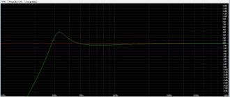
indeed, if we err slightly against the truth and use the fact that the antenna within one range is indeed very broadband, then it works quite acceptably with a 50 or 75 ohm cable without special matching and tuning measures. But, if we look at everything in detail, it turns out that the antenna resistance very much depends on the shape of the frames and, of course, on their size. For example, the graph on the right shows the biquad impedance curves depending on the physical size of the frames. And we already know that the antenna is very broadband and can successfully operate not only at the resonant frequency but also near it. Therefore, biquadrat antennas are sometimes called not a resonant antenna, but a band antenna. Angle “a” is the physical angle between the vertical and the frame elements.
It will be interesting➡ We assemble a step-up transformer with our own hands
In this particular case, the angle is 45 degrees, that is, the shape of the frames are perfect squares. On the graphs you can see that if the perimeter of the frames exactly corresponds to the wavelength (the side of the square is equal to 0.25 of the perimeter), their impedance lies in the range of 50-60 ohms. If the side of the square is increased to 0.33, then the resistance increases to 120 ohms. It is calculated that the maximum gain of the biquad and the best directional properties will be when the length of the side of the square is equal to 0.375. Of course, the resistance increases many times over - up to 600-700 ohms, which is of course a lot even for our idea. The second graph, on the left, shows the dependence of resistance on angle “a”. If we consider the resistance graph with a square side length equal to 0.25 perimeter - directly resonant, but with an angle of the side to the vertical equal to 60 degrees, then we will find that the resistance of the biquadrat, or Kharchenko antenna, will not be 50 ohms, but 100!
Large Kharchenko antenna.
Thus, we obtain an antenna with a circular radiation pattern with minimal difficulties in manufacturing and configuration. If one antenna is rotated 90 degrees not only in the horizontal, but also in the vertical plane, then we get an antenna with circular polarization and a circular radiation pattern. The simplest calculation will show you that to form an angle of 60 degrees between the vertical and the sides of the rhombus (with a perimeter equal to the wavelength, in our case 2000 mm), the height of the biquadrat should be 1000 mm, and the distance between the extreme points 866 mm.
The resistance of one such “biquadratin” will be 100 ohms. To obtain a circular radiation pattern, two biquads are placed at an angle of 90 degrees to each other and connected to each other using a quarter-wave transformer-phase shifter made of a cable with a resistance of 50 Ohms. Taking into account the shortening factor (for RG-58), this is a segment of 34.2 cm. You have probably already noticed my love for copper wire and sewer pipes? So it’s true, I don’t know a better material for modeling and practical manufacturing of VHF antennas.
Although, of course, everything described below can be replaced with your own structure made of wood, for example, or other available insulating material, and the wires with pipes or strips of tin or galvanized steel. Don't forget that there is an easy way to evaluate the quality of the antenna dielectric material.
If I had not been a radio engineer in my youth, I would simply repeat the almost universally repeated phrase that the gain of the Kharchenko antenna is 6-8 dB. But since I understand the issue, I can say that the gain of one Kharchenko antenna (when it is 50 ohm) will not be more than 4 dB. In our case, when the resistance of one antenna is higher and the efficiency is better, maybe a little more. There will be no gain in gain from two antennas forming a circular radiation pattern, but we can safely say that in this antenna, let’s call it conventionally “two diamonds” (in appearance), the gain will be at least 4 dB in all directions.
So, let's move on to the design. Due to the fact that plastic tube sticks from McDonald's balloons are no longer suitable, the idea came to mind to use plastic sticks from children's skis, which the eldest grandson has already outgrown, and the youngest no longer wants red. The length and diameter are suitable, only the color let us down...