Since I spend quite a lot of time in the workshop, I try to arrange it for maximum efficiency. The same goes for various tool improvements. In particular, one day I needed to make a speed controller for the electric motor of a sharpener, since I have to work with different materials, and some of them are sensitive to friction. Plus, the electric motor has a smooth start with simple controls. Assembling the speed controller of a commutator engine with your own hands without loss of power is not very difficult. Next, I will show the progress of the work and show how to improve the existing scheme. After all, as you know, the first principle of electrical engineering is: the simpler, the better.
Source forumcnc.ru
Commutator motor operation
For someone who understands the principles of operation of a commutator engine, starting will not seem like a difficult task.
Let's take a quick look to understand the essence of the problem. The above figure schematically shows: The principle of operation of a commutator motor
- The design of a commutator motor from stator windings (rectangle with oblique lines), commutator (narrow orange rectangles), brushes (vertical gray rectangles).
- The electrical connection diagram is for direct current. The blue line shows the minus (north pole), the red line shows the plus (south pole).
- Along the horizontal row, cross sections of the rotor and stator are given (schematically). For simplicity, the stationary part of the motor is represented by two poles, although in reality there are more. The northern one is marked in blue, the southern one is marked in red. If you disassemble the electric motor, you can observe a similar picture with your own eyes. The cut of the rotor resembles the crossbar of a magnetron.
How it works. The engine manifold is formed by sections, which can be seen schematically in the figure. The copper drum is divided by insulating crossbars into even rows of lamellas. Each section is equipped with leads on strictly opposite sides of the circle. Accordingly, two brushes are suitable. One for each side. One section receives power, and a field appears in the coil. Let's see where this leads.
- In the upper part of the figure we see the direct connection of the stator and rotor. The field is distributed so that the shaft begins to rotate clockwise. Charges of the same signs on the stator and rotor repel, while charges of opposite signs attract. The section will travel a certain distance in a circle, the brushes are transferred to the next one, and it begins to work. The cycle is repeated as long as the supply voltage is supplied.
- By turning on the brushes towards the stator, we change the distribution of charges on the rotor to the opposite one. See what the reverse leads to (lower part of the picture). The motor shaft rotates counterclockwise. As before, charges of the same signs attract, charges of different signs repel.
To change the direction of movement of the washing machine motor, special contactors (power relays) are used. If necessary, the rotor is turned on towards the stator, a reverse is formed
One thing is important: if the shaft does not rotate correctly, change the direction in which the windings are turned on. We’ll tell you how to do it later.
Control principle
When the rotation speed of the motor shaft is set by a resistor in output circuit 5, a sequence of pulses is formed at the output to unlock the triac by a certain angle. The speed of rotation is monitored by a tachogenerator, which occurs in digital format. The driver converts the received pulses into an analog voltage, which is why the shaft speed is stabilized at a single value, regardless of the load. If the voltage from the tachogenerator changes, the internal regulator will increase the level of the output control signal of the triac, which will lead to an increase in speed.
The microcircuit can control two linear accelerations, allowing you to achieve the dynamics required from the engine. One of them is installed on the Ramp 6 output of the circuit. This regulator is used by washing machine manufacturers themselves, so it has all the advantages to be used for domestic purposes. This is ensured by the presence of the following blocks:
- Voltage stabilizer to ensure normal operation of the control circuit. It is implemented at pins 9, 10.
- Rotation speed control circuit. Implemented using MS pins 4, 11, 12. If necessary, the controller can be switched to an analog sensor, then pins 8 and 12 are combined.
- Starting impulse block. It is implemented at pins 1, 2, 13, 14, 15. It adjusts the duration of control pulses, delays, generates them from a constant voltage and calibrates.
- Sawtooth voltage generation device. Pins 5, 6 and 7. It is used to control the speed according to the set value.
- Control amplifier circuit. Pin 16. Allows you to adjust the difference between the set and actual speed.
- Current limiting device at pin 3. When the voltage on it increases, the triggering angle of the triac decreases.
The use of such a circuit ensures full control of the commutator motor in any mode. Thanks to forced acceleration control, it is possible to achieve the required acceleration speed to a given rotation speed. Such a regulator can be used for all modern washing machine motors used for other purposes.
https://youtube.com/watch?v=yLHAaZTr0hQ
Source
Converters on electronic keys
Common thyristor regulators with a simple operating circuit.
Thyristor, works in alternating current network.
A separate type is the AC voltage stabilizer. The stabilizer contains a transformer with numerous windings.
DC stabilizer circuit
24 volt thyristor charger
To a 24 volt voltage source. The principle of operation is to charge a capacitor and a locked thyristor, and when the capacitor reaches voltage, the thyristor sends current to the load.
Proportional Signal Process
Signals arriving at the system input form feedback. Let's take a closer look using a microcircuit.
Chip TDA 1085
The TDA 1085 chip pictured above provides feedback control of a 12V, 24V motor without loss of power. It is mandatory to contain a tachometer, which provides feedback from the engine to the control board. The stabilization sensor signal goes to a microcircuit, which transmits the task to the power elements - to add voltage to the motor. When the shaft is loaded, the board increases the voltage and the power increases. By releasing the shaft, the tension decreases. The revolutions will be constant, but the power torque will not change. The frequency is controlled over a wide range. Such a 12, 24 volt motor is installed in washing machines.
Industrial regulators, consisting of 12, 24 volt controllers, are filled with resin and therefore cannot be repaired. Therefore, a 12V device is often made independently. A simple option using the U2008B chip. The controller uses current feedback or soft start. If the latter is used, elements C1, R4 are required, jumper X1 is not needed, but with feedback, vice versa.
When assembling the regulator, choose the right resistor. Since with a large resistor there may be jerks at the start, and with a small resistor the compensation will be insufficient.
Speed controllers for single-phase and three-phase 24, 12 volt motors are a functional and valuable device, both in everyday life and in industry.
Frequency regulation
Special devices, frequency converters (other names: inverter, frequency converter, driver), are connected to an electrical machine. By rectifying the supply voltage, the frequency converter internally generates the required frequency and voltage values and supplies them to the electric motor.
The converter calculates the necessary parameters for blood pressure control independently, according to internal algorithms programmed by the device manufacturer.
Advantages of frequency regulation
.
- Smooth control of the electric motor rotation speed is achieved.
- Changing the speed and direction of rotation of the engine.
- Automatic maintenance of required parameters.
- Cost-effective control system.
The only drawback that you can put up with is the need to purchase a frequency converter. The prices for such devices are absolutely sky-high, and within 150 euros, you can get a converter for a 2 kW motor.
Advantages and disadvantages
To summarize, we highlight the following advantages of CLEBO A3:
- Navigation based on camera and gyroscope.
- Building a room map.
- Build quality and performance.
- Extended delivery set.
- Several operating modes + polisher mode.
- Setting up a cleaning schedule.
- Control from smartphone and remote control.
- Working with voice assistants.
- Low noise level.
The downside of the iCLEBO A3 is the poorly implemented wet cleaning function, which is just wiping the floor with a dampened cloth without electronic control
It is also important to understand that the device is controlled via Bluetooth, that is, it will not be possible to start it remotely, for example, while at work. Well, the cost of a robot vacuum cleaner at 29,900 rubles, let’s be objective, is not affordable for everyone. Otherwise, there are no complaints about this model.
Otherwise, there are no complaints about this model.
Finally, we recommend looking at the rating of the best robot vacuum cleaners with a camera:
Analogues:
- Xiaomi Mijia LDS Vacuum Cleaner
- GUTREND SENSE 410
- Roborock S6 Pure
- Ecovacs DeeBot OZMO 900
- HOBOT Legee-688
- iRobot Roomba 960
- Okami U90 Vision
Voltage regulation
Speed control in this way is associated with a change in the so-called engine slip - the difference between the rotation speed of the magnetic field created by the stationary engine stator and its moving rotor:
n1—magnetic field rotation speed
n2—rotor rotation speed
In this case, sliding energy is necessarily released - which causes the motor windings to heat up more.
This method has a small control range, approximately 2:1, and can also only be carried out downwards - that is, by reducing the supply voltage.
When regulating speed in this way, it is necessary to install oversized motors.
But despite this, this method is used quite often for low-power motors with a fan load.
In practice, various regulator circuits are used for this.
Autotransformer voltage regulation
An autotransformer is an ordinary transformer, but with one winding and taps from some of the turns. In this case, there is no galvanic isolation from the network, but in this case it is not needed, so savings are achieved due to the absence of a secondary winding.
The diagram shows autotransformer T1, switch SW1, which receives taps with different voltages, and motor M1.
The adjustment is done in steps; usually no more than 5 steps of regulation are used.
Advantages of this scheme:
- undistorted output voltage waveform (pure sine wave)
- good overload capacity of the transformer
Flaws:
- large mass and dimensions of the transformer (depending on the power of the load motor)
- all the disadvantages inherent in voltage regulation
Thyristor engine speed controller
This circuit uses keys - two thyristors connected back-to-back (the voltage is alternating, so each thyristor passes its own half-wave of voltage) or a triac.
The control circuit regulates the moment of opening and closing of the thyristors relative to the phase transition through zero; accordingly, a piece is “cut off” at the beginning or, less often, at the end of the voltage wave.
This changes the rms voltage value.
This circuit is quite widely used to regulate active loads - incandescent lamps and all kinds of heating devices (so-called dimmers).
Another method of regulation is to skip half-cycles of the voltage wave, but at a network frequency of 50 Hz this will be noticeable for the motor - noise and jerking during operation.
To control motors, regulators are modified due to the characteristics of the inductive load:
- install protective LRC circuits to protect the power switch (capacitors, resistors, chokes)
- add a capacitor at the output to adjust the voltage waveform
- limit the minimum voltage regulation power - for guaranteed engine start
- use thyristors with a current several times higher than the electric motor current
Advantages of thyristor regulators:
Flaws:
- can be used for low power engines
- During operation, noise, crackling, and jerking of the engine may occur.
- when using triacs, a constant voltage is applied to the motor
- all the disadvantages of voltage regulation
It is worth noting that in most modern mid- and high-level air conditioners, the fan speed is adjusted in this way.
Transistor voltage regulator
As the manufacturer himself calls it, an electronic autotransformer or PWM regulator.
The voltage is changed using the PWM (pulse width modulation) principle, and transistors are used in the output stage - field-effect or bipolar with insulated gate (IGBT).
The output transistors are switched at a high frequency (about 50 kHz); if you change the width of the pulses and pauses between them, the resulting voltage at the load will also change. The shorter the pulse and the longer the pause between them, the lower the resulting voltage and power input.
For a motor, at a frequency of several tens of kHz, a change in the pulse width is equivalent to a change in voltage.
The output stage is the same as that of a frequency converter, only for one phase there is a diode rectifier and two transistors instead of six, and the control circuit changes the output voltage.
Advantages of an electronic autotransformer:
- Small dimensions and weight of the device
- Low cost
- Clean, undistorted current output waveform
- No hum at low speeds
- 0-10 Volt signal control
Weak sides:
- The distance from the device to the engine is no more than 5 meters (this disadvantage is eliminated when using a remote controller)
- All the disadvantages of voltage regulation
Regulator for 220 Volt motors
A self-made engine speed controller can be mounted in the tool body or made in a separate housing, which significantly improves the convenience and versatility of its use. The self-contained controller can be used as needed for various power tools.
The simplest speed controller for a commutator motor can be made with your own hands in several ways - on a printed circuit board, mounted or mounted on a circuit board.
Main elements of the scheme:
- triac BTA 16;
- dinistor DB 3;
- variable resistor 500 kOhm;
- fixed resistor 2 kOhm;
- capacitance 100 nF;
- foil PCB or circuit board;
- solder;
- rosin;
- ferric chloride;
- laser disc marker and pencil.
Cut a piece of foil PCB of the required size, sand it, degrease it and draw a diagram of the device for subsequent etching in ferric chloride.
After etching, rinse, drill holes for soldering circuit elements, tin the printed tracks and pads, and assemble the circuit.
Instead of making your own printed circuit board, you can buy a ready-made circuit board.
By installing the assembled circuit into an easy-to-use case, you will receive a 220V speed controller made by yourself.
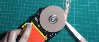
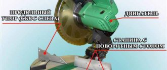
Why adjust the rotation speed of the grinder disc at all?
- When cutting metal of different thicknesses, the quality of work greatly depends on the speed of rotation of the disk. If you are cutting hard and thick material, you must maintain maximum rotation speed. When processing thin sheet metal or soft metal (for example, aluminum), high speeds will lead to melting of the edge or rapid blurring of the working surface of the disk;
- Cutting and sawing stone and tile at high speed can be dangerous. In addition, the disk, which rotates at high speeds, knocks small pieces out of the material, making the cutting surface chipped. Moreover, different speeds are selected for different types of stone. Some minerals are processed at high speeds;
- Grinding and polishing work is in principle impossible without adjusting the rotation speed. By setting the speed incorrectly, you can damage the surface, especially if it is a paint coating on a car or a material with a low melting point;
- The use of discs of different diameters automatically implies the presence of a regulator. Changing a disk Ø115 mm to Ø230 mm, the rotation speed must be reduced by almost half. And holding a grinder with a 230 mm disc rotating at a speed of 10,000 rpm is almost impossible to hold in your hands;
- Polishing of stone and concrete surfaces, depending on the type of crowns used, is carried out at different speeds. Moreover, when the rotation speed decreases, the torque should not decrease;
- When using diamond discs, it is necessary to reduce the number of revolutions, since their surface quickly fails due to overheating. Of course, if your grinder works only as a cutter for pipes, angles and profiles, you won’t need a speed controller. And with the universal and versatile use of angle grinders, it is vital.
Application of electronic regulators
The use of powerful asynchronous motors is impossible without the use of appropriate speed controllers. Such converters are used for the following purposes:
- Stepped acceleration and the ability to reduce engine speed when the load decreases allows you to reduce energy consumption. The use of frequency converters with powerful asynchronous motors allows you to halve your energy costs.
- Protection of electronic mechanisms. Frequency converters allow you to monitor pressure, temperature and a number of other parameters. When using an engine as a pump drive, a pressure sensor can be installed in a container into which liquid or air is pumped, which is responsible for controlling the mechanism and preventing its failure.
- Ensuring a smooth start. When starting the electric motor, when the motor immediately begins to operate at maximum speed, the drive experiences an increased load. The use of a speed controller ensures smooth starting, which guarantees the maximum possible durability of the drive and the absence of serious damage.
- Maintenance costs for pumps and the power units themselves are reduced. The presence of speed regulators reduces the risk of breakdowns of individual mechanisms and the entire drive.
The operating scheme used by frequency converters is similar to that of most household appliances. Similar devices are also used in welding machines, UPSs, power supply for PCs and laptops, voltage stabilizers, lamp ignition units, as well as in monitors and LCD TVs.
Frequency regulation
Just recently (10 years ago), there were a limited number of frequency controllers for motor speeds on the market, and they were quite expensive. The reason was that there were no cheap high-voltage power transistors and modules.
But developments in the field of solid-state electronics have made it possible to bring power IGBT modules to the market. As a consequence, there is a massive appearance on the market of inverter air conditioners, welding inverters, and frequency converters.
At the moment, frequency conversion is the main way to regulate the power, performance, speed of all devices and mechanisms driven by an electric motor.
However, frequency converters are designed to control three-phase electric motors.
Single-phase motors can be controlled by:
- specialized single-phase inverters
- three-phase inverters with the exception of the capacitor
Converters for single-phase motors
Currently, only one manufacturer announces serial production of a specialized inverter for capacitor motors - INVERTEK DRIVES.
This is the Optidrive E2 model
For stable engine starting and operation, special algorithms are used.
In this case, frequency adjustment is possible upward, but in a limited frequency range, this is prevented by a capacitor installed in the phase-shifting winding circuit, since its resistance directly depends on the frequency of the current:
f - current frequency
C - capacitance of the capacitor
The output stage uses a bridge circuit with four output IGBT transistors:
Optidrive E2 allows you to control the motor without removing the capacitor from the circuit, that is, without changing the motor design - in some models this is quite difficult to do.
Advantages of a specialized frequency converter:
- intelligent motor control
- Stably stable engine operation
- Huge capabilities of modern inverters:
- the ability to control the operation of the engine to maintain certain characteristics (water pressure, air flow, speed under changing load)
- numerous protections (motor and device itself)
- sensor inputs (digital and analogue)
- various outputs
- communication interface (for control, monitoring)
- preset speeds
- PID controller
Disadvantages of using a single-phase inverter:
Using a state of emergency for three-phase motors
A standard frequency converter has a three-phase voltage at its output. When connecting a single-phase motor to it, remove the capacitor from it and connect it according to the diagram below:
The geometric arrangement of the windings relative to each other in the stator of an asynchronous motor is 90°:
The phase shift of the three-phase voltage is -120°, as a consequence of this - the magnetic field will not be circular, but pulsating and its level will be less than with a power supply with a shift of 90°.
In some capacitor motors, the additional winding is made of thinner wire and therefore has a higher resistance.
When operating without a capacitor, this will lead to:
- stronger heating of the winding (service life is reduced, short circuits and interturn short circuits are possible)
- different current in the windings
Many inverters have protection against current asymmetry in the windings; if it is impossible to disable this function in the device, operation using this circuit will be impossible
Advantages:
- lower cost compared to specialized inverters
- Huge selection of power and manufacturers
- wider frequency control range
- all the advantages of the inverter (inputs/outputs, intelligent operating algorithms, communication interfaces)
Disadvantages of the method:
- the need for preliminary selection of the inverter and motor for joint operation
- pulsating and reduced torque
- increased heating
- no warranty in case of failure, because Three-phase inverters are not designed to work with single-phase motors
Each of us has some kind of electrical appliance at home that has been working in the house for more than one year. But over time, the power of the technology weakens and does not fulfill its intended purpose.
This is when you should pay attention to the insides of the equipment. Mostly problems arise with the electric motor, which is responsible for the functionality of the equipment.
Then you should turn your attention to a device that regulates engine speed without reducing its power.
How to choose a regulator
There are several characteristics by which you need to choose a speed controller for a car, machine electric motor, or household needs:
- Control type. For commutator motors, there are regulators with a vector or scalar control system. The former are more often used, but the latter are considered more reliable;
- Power. This is one of the most important factors for choosing an electrical frequency converter. It is necessary to select a frequency generator with a power that corresponds to the maximum permissible on the protected device. But for a low-voltage motor it is better to choose a regulator more powerful than the permissible watt value;
- Voltage. Naturally, everything here is individual, but if possible, you need to buy a speed controller for an electric motor, the circuit diagram of which has a wide range of permissible voltages;
- Frequency range. Frequency conversion is the main task of this device, so try to choose a model that will best suit your needs. Let's say, for a manual router, 1000 Hertz will be enough;
- According to other characteristics. This is the warranty period, the number of inputs, the size (there is a special attachment for desktop machines and hand tools).
Devices from the Sinus, E-Sky and Pic brands have proven themselves well.
At the same time, you also need to understand that there is a so-called universal rotation regulator. This is a frequency converter for brushless motors.
Photo - regulator diagram for brushless motors
There are two parts in this circuit - one is logical, where the microcontroller is located on the chip, and the second is power. Basically, such an electrical circuit is used for a powerful electric motor.
Video: electric motor speed controller with SHIRO V2
Changing the speed of an IM with a squirrel-cage rotor
There are several ways:
- Rotation control by changing the electromagnetic field of the stator: frequency regulation and changing the number of pole pairs.
- Changing the slip of the electric motor by decreasing or increasing the voltage (can be used for IMs with a wound rotor).
Frequency regulation
In this case, the adjustment is made using a frequency conversion device connected to the engine. For this purpose, powerful thyristor converters are used. The process of frequency regulation can be considered using the example of the EMF formula of a transformer:
U1=4.44w1k1fΦ
This expression means that in order to maintain a constant magnetic flux, which means maintaining the overload capacity of the electric motor, the supply voltage level should be adjusted simultaneously with frequency conversion. If the expression calculated by the formula is saved:
U1/f1=U'1/f'1
then this means that the critical moment has not been changed. And the mechanical characteristics correspond to the figure below; if you do not understand what these characteristics mean, then in this case the adjustment occurs without loss of power and torque.
The advantages of this method are:
- smooth regulation;
- changing the rotor speed up and down;
- rigid mechanical characteristics;
- efficiency.
There is only one drawback - the need for a frequency converter, i.e. increase in the cost of the mechanism. By the way, on the modern market there are models with single-phase and three-phase input, the cost of which with a power of 2-3 kW is in the range of 100-150 dollars, which is not too expensive for full adjustment of the drive of machine tools in a private workshop.
Switching the number of pole pairs
This method is used for multi-speed motors with complex windings that allow you to change the number of pairs of its poles. The most widely used are two-speed, three-speed and four-speed IMs. The adjustment principle is easiest to consider on the basis of a two-speed IM. In such a machine, the winding of each phase consists of two half-windings. The rotation speed changes when connecting them in series or parallel.
In a four-speed electric motor, the winding is made in the form of two parts independent from each other. When the number of pole pairs of the first winding changes, the speed of the electric motor changes from 3000 to 1500 rpm. Using the second winding, rotation is adjusted at 1000 and 500 rpm.
When the number of pole pairs changes, the critical moment also changes. To keep it unchanged, it is necessary to simultaneously regulate the supply voltage while changing the number of pole pairs, for example, by switching the star-delta circuit and their variations.
Advantages of this method:
- rigid mechanical characteristics of the engine;
- high efficiency.
Flaws:
- step adjustment;
- large weight and overall dimensions;
- high cost of the electric motor.
Engine speed controller from Aliexpress
On the rear panel of the speed controller there is a cable of wires, in which one pair is “phase” and “zero” and the second pair goes to the tachometer of the electronic engine. If only 2 main wires are connected to the motor from the washing machine through the controller, the motor will operate at maximum speed. In order to be able to regulate the speed, it is necessary to connect the wires coming from the tachometer.
You can connect to such a device not only motors from a washing machine, but also motors removed from old drills and other unnecessary power tools. The main thing when preparing for work is to correctly install the electrical system. Work on connecting the control device to the engine must be carried out in the following sequence:
If the speed controller will be used with only one electricity consumer, then after finishing work it is enough to turn off the device on the front panel and also disconnect it from the network.
Many DIYers encounter one problem when connecting a controller of this type. The wires coming from the rheostat are placed in a connector that does not fit into the standard motor socket of most washing machine models. This problem is solved by resoldering a suitable plug block, which can be purchased in specialized stores or removed from the washing machine from which the motor was removed.
Description of 4 electric motor speed controller circuits
First scheme
A sawtooth voltage generator (frequency 150 Hz) is implemented on transistor VT1 (unijunction). Operational amplifier DA1 plays the role of a comparator that creates PWM based on transistor VT2. The result is a PWM engine speed controller.
The rotation speed is changed by variable resistor R5, which changes the duration of the pulses. Since the amplitude of the PWM pulses is constant and equal to the supply voltage of the electric motor, it never stops even at a very low rotation speed.
Second scheme
It is similar to the previous one, but the operational amplifier DA1 (K140UD7) is used as the master oscillator.
This op-amp functions as a voltage generator producing triangular-shaped pulses and having a frequency of 500 Hz. Variable resistor R7 sets the rotation speed of the electric motor.
Third scheme
It is unique, built on the popular NE555 timer. The master oscillator operates with a frequency of 500 Hz. The pulse width, and therefore the engine speed, can be changed from 2% to 98%.
The weak point in all the above schemes is that they do not have an element for stabilizing the rotation speed when the load on the DC motor shaft increases or decreases. You can resolve this problem using the following diagram:
Like most similar regulators, the circuit of this regulator has a master voltage generator that produces triangular pulses with a frequency of 2 kHz. The entire specificity of the circuit is the presence of positive feedback (POS) through elements R12, R11, VD1, C2, DA1.4, which stabilizes the rotation speed of the electric motor shaft when the load increases or decreases.
When setting up a circuit with a specific motor, resistance R12, choose a PIC depth at which self-oscillations of the rotation speed do not occur when the load changes.
Single channel motor controller
The device controls one motor, powered by voltage in the range from 2 to 12 volts.
The main design elements of the regulator are shown in the photo. 3. The device consists of five components: two variable resistance resistors with a resistance of 10 kOhm (No. 1) and 1 kOhm (No. 2), a transistor model KT815A (No. 3), a pair of two-section screw terminal blocks for the output for connecting a motor (No. 4) and input for connecting a battery (No. 5).
The operating procedure of the motor controller is described in the electrical diagram (Fig. 1). Taking into account the polarity, a constant voltage is supplied to the XT1 connector. The light bulb or motor is connected to the XT2 connector. A variable resistor R1 is turned on at the input; rotating its knob changes the potential at the middle output as opposed to the minus of the battery. Through current limiter R2, the middle output is connected to the base terminal of transistor VT1. In this case, the transistor is switched on according to a regular current circuit. The positive potential at the base output increases as the middle output moves upward from the smooth rotation of the variable resistor knob. There is an increase in current, which is due to a decrease in the resistance of the collector-emitter junction in transistor VT1. The potential will decrease if the situation is reversed.
Electrical circuit diagram
A printed circuit board measuring 20x30 mm is required, made of a fiberglass sheet foiled on one side (permissible thickness 1-1.5 mm). Table 1 provides a list of radio components.
For further work, you need to download the archive file located at the end of the article, unzip it and print it. The regulator drawing (termo1 file) is printed on glossy paper, and the installation drawing (montag1 file) is printed on a white office sheet (A4 format).
Next, the drawing of the circuit board (No. 1 in photo. 4) is glued to the current-carrying tracks on the opposite side of the printed circuit board (No. 2 in photo. 4). It is necessary to make holes (No. 3 in photo. 14) on the installation drawing in the mounting locations. The installation drawing is attached to the printed circuit board with dry glue, and the holes must match. Photo 5 shows the pinout of the KT815 transistor.
The input and output of terminal blocks-connectors are marked white. A voltage source is connected to the terminal block via a clip. A fully assembled single-channel regulator is shown in the photo. The power source (9 volt battery) is connected at the final stage of assembly. Now you can adjust the shaft rotation speed using the motor; to do this, you need to smoothly rotate the variable resistor adjustment knob.
To test the device, you need to print a disk drawing from the archive. Next, you need to paste this drawing (No. 1) onto thick and thin cardboard paper (No. 2). Then, using scissors, a disc is cut out (No. 3).
The resulting workpiece is turned over (No. 1) and a square of black electrical tape (No. 2) is attached to the center for better adhesion of the surface of the motor shaft to the disk. You need to make a hole (No. 3) as shown in the image. Then the disk is installed on the motor shaft and testing can begin. The single-channel motor controller is ready!
System design
The commutator type motor consists mainly of a rotor, a stator, as well as brushes and a tachogenerator.
- The rotor is part of the rotation, the stator is an external type of magnet.
- Brushes, which are made of graphite, are the main part of the sliding contact, through which voltage is applied to the rotating armature.
- A tachogenerator is a device that monitors the rotation characteristics of a device. If there is a violation in the regularity of the rotation process, then it adjusts the voltage level entering the engine, thereby making it smoother and slower.
- Stator. Such a part may include not one magnet, but, for example, two pairs of poles. At the same time, instead of static magnets, there will be coils of electromagnets. Such a device is capable of performing work both from direct current and alternating current.
Scheme of the speed controller of the commutator motor
Special frequency converters are used in the form of speed controllers for 220 V and 380 V electric motors. Such devices are considered high-tech, and they help to radically transform the current characteristics (signal shape, as well as frequency). They are equipped with powerful semiconductor transistors, as well as a pulse-width modulator. The entire process of operating the device occurs through the control of a special unit on a microcontroller. The change in speed in the rotation of the motor rotor occurs quite slowly.
It is for this reason that frequency converters are used in loaded devices. The slower the acceleration process occurs, the less load will be placed on the gearbox, as well as the conveyor. In all frequency generators you can find several degrees of protection: by load, current, voltage and other indicators.
Some models of frequency converters supply power from a single-phase voltage (it will reach 220 Volts) and create a three-phase voltage from it. This helps to connect an asynchronous motor at home without the use of particularly complex circuits and designs. In this case, the consumer will not lose power while working with such a device.
Why use such a device-regulator?
If we talk about regulator motors, the required speed is:
- For significant energy savings. So, not every mechanism needs a lot of energy to perform the work of rotating the motor; in some cases, rotation can be reduced by 20-30 percent, which will help significantly reduce energy costs by several times.
- For the protection of all mechanisms, as well as electronic types of circuits. Using the converter frequency, you can exercise certain control over the overall temperature, pressure, as well as other indicators of the device. In the case when the engine operates as a specific pump, then a specific pressure sensor should be inserted into the container into which air or liquid is pumped. When the maximum mark is reached, the motor will simply automatically stop working.
- For the soft start process. There is no particular need to use additional electronic equipment - everything can be done by changing the settings of the frequency converter.
- To reduce device maintenance costs. With the help of such speed controllers in 220 V engines, the possibility of failure of devices, as well as certain types of mechanisms, can be significantly reduced.
The circuits used to create frequency converters in an electric motor are widely used in most household devices. Such a system can be found in wireless power supplies, welding machines, phone chargers, power supplies for personal computers and laptops, voltage stabilizers, lamp ignition units for backlighting modern monitors, as well as LCD TVs.
The easiest way
Many power tools that use commutator motors have a small rheostat installed, which can be used to control the rotor speed with virtually no loss of power. Such an element can be removed from a faulty drill, screwdriver or hammer drill and installed in series with an electric motor. If a suitable rheostat is not available, then such a part can be purchased inexpensively at a specialized store.
A small difficulty is that the working stroke of such an adjustment mechanism is very small and it can be very difficult to set the engine speed at the required level. This problem is usually solved by installing additional mechanical converters of mechanical energy. This way, it will be possible to correctly set the rotor speed, as well as ensure that the device is fixed at the required level.
In addition to rheostats from hand-held electric tools, you can use ready-made store-bought devices that just need to be plugged into an outlet, and the motor leads connected directly to the adjusting device. Such products allow you to change the voltage over a very wide range, so choosing the position of the control toggle switch for certain engine speeds will not be difficult. An important advantage of store-bought rheostats is the ability to use them with other electronic devices, that is, it is enough to purchase a product once, with which you can adjust a large number of devices, not limited to electric motors.
Power speed regulator
Work principles
A 220 V electric motor speed controller without loss of power is used to maintain the initial set shaft speed. This is one of the basic principles of this device, which is called a frequency regulator.
With its help, the electrical device operates at the set engine speed and does not reduce it. The engine speed controller also affects the cooling and ventilation of the motor. With the help of power, the speed is set, which can be either raised or reduced.
Many people have asked the question of how to reduce the speed of a 220 V electric motor. But this procedure is quite simple. One has only to change the frequency of the supply voltage, which will significantly reduce the performance of the motor shaft. You can also change the power supply to the motor by activating its coils. Electrical control is closely related to the magnetic field and motor slip. For such actions, they mainly use an autotransformer and household regulators, which reduce the speed of this mechanism. But it is also worth remembering that engine power will decrease.
Shaft rotation
Engines are divided into:
- asynchronous,
- collector
The speed controller of an asynchronous electric motor depends on the current connection to the mechanism. The essence of the operation of an asynchronous motor depends on the magnetic coils through which the frame passes. It rotates on sliding contacts. And when, when turning, it turns 180 degrees, then through these contacts the connection will flow in the opposite direction. This way the rotation will remain the same. But with this action the desired effect will not be obtained. It will come into force after a couple of dozen frames of this type are added to the mechanism.
The commutator motor is used very often. Its operation is simple, since the transmitted current passes directly - because of this, the power of the electric motor is not lost, and the mechanism consumes less electricity.
The washing machine motor also needs power adjustment. For this purpose, special boards were made that cope with their job: the engine speed control board from a washing machine has multifunctional use, since its use reduces the voltage, but does not lose rotation power.
The circuit of this board has been verified. All you have to do is install diode bridges and select an optocoupler for the LED. In this case, you still need to put a triac on the radiator. Basically, engine adjustment starts at 1000 rpm.
If you are not satisfied with the power regulator and its functionality is lacking, you can make or improve the mechanism. To do this, you need to take into account the current strength, which should not exceed 70 A, and heat transfer during use. Therefore, an ammeter can be installed to adjust the circuit. The frequency will be small and will be determined by capacitor C2.
Next, you should configure the regulator and its frequency. When outputting, this pulse will go out through a push-pull amplifier using transistors. You can also make 2 resistors that will serve as an output for the computer's cooling system. To prevent the circuit from burning out, a special blocker is required, which will serve as double the current value. So this mechanism will work for a long time and in the required volume. Power regulating devices will provide your electrical appliances with many years of service without special costs.
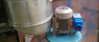
Which engine to choose to make a circular machine
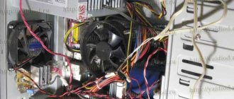
Every owner would like to have a device for working with lumber in a garage, in a country house, in a private house or when renovating a city apartment. But even a hand-held circular saw costs from 10,000 rubles. In this article we will talk about how a circular machine is made from an engine from a washing machine that has served its life. This homemade electric saw, assembled with your own hands at home, is capable of unraveling boards five centimeters thick. At the same time, it weighs just over 20 kilograms and is easily transported in the trunk of a car.
A circular saw is always useful on the farm: at the dacha or in a private house. But not everyone can afford a good expensive tool, and a cheap analogue quickly breaks down. The way out of the situation is to make a circular saw with your own hands. For example, you can make it from an engine from an old automatic washing machine, which is a shame to throw away and takes up space.
The working motor from an automatic washing machine should not gather dust in the garage. Even a home craftsman can find a use for it. We will tell you how to make a homemade circular from a washing machine engine.
This tool will help you cut wood and master carpentry.
However, be careful: careless use of a homemade machine can lead to unpleasant consequences. Therefore, before you take on a job, you must be completely confident in your abilities.
A 350 mm disk will require 1 kW of energy to start. A disk with a diameter of 170 mm will require about 500 W. Therefore, you can install a motor from an old washing machine.
In the washing machine, the speed is controlled by a tachometer, which is controlled by a control module. But it is impossible to connect a module to the circular, so install a voltage regulator. Use the wiring diagram to correctly install the motor.
You have figured out which motor is needed and how to connect it. Now consider the design diagram of a circular saw.
The main load will be on the moving elements. This:
- saw and electric motor shaft;
- motor pulley and saw shaft;
- drive belt.
Let's look at the features of each of them:
- The drive belt does not have to be taken from the washing machine; other belts can be used. The main thing is that they have serrations, like a V-belt.
- Flow grooves need to be made on the small pulley. The belt will cling to them during operation, which will prevent slipping.
- A larger disc is welded onto the large pulley, which will prevent the belt from slipping off.
- To fasten the circular saw, use a shaft into which it is mounted, as well as a washer and nut, which are used to secure it. It is recommended to select or take this kit from the factory to ensure the drive is secured as securely as possible.
When creating a design, you need to take into account that it is designed for a three-hundredth disk. Of course, a self-made circular machine is only suitable for household use. Therefore, try not to overload the engine.
Often such machines are stored in the yard, on the street, so protect the electrical part from moisture.
The frame is made of metal sheet 3 mm thick. Before making the frame, prepare a 30 mm metal corner.
As shown in the photo above, the craftsman installed the frame into homemade pipe racks. Now it is possible to adjust the height of the device. However, it is recommended to make a solid frame by welding pieces of corner together. Strong vibration over time loosens the fastenings of bolts and other elements.
We suggest you read: Zanussi washing machine does not turn on reasons
Please note that the mini circular saw varies in size. It is much smaller than usual and can fit into a pantry when stored.
A washing machine is a useful thing in the household. However, over time the device breaks down. There is an element in the washing machine that should not just be lying around in the garage - this is the motor. It makes an excellent circular saw.
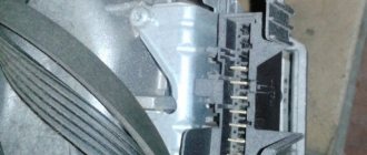
Checking the washing machine motor and determining the assignment of the terminals
Before assembling the speed controller with your own hands, you need to check the performance of the motor. In a washing machine, this part is connected via a terminal block. Typically, the connector has the following electrical terminals:
- 2 wires from the commutator brushes.
- 2 or 3 wires from the stator.
- 2 wires from the tachometer.
If there are 3 wires coming from the stator, then in such a motor it is possible to change the speed by alternately connecting the wires to the current source. Without any additional devices, a motor with two windings can be used in two modes. This feature is explained by the need for higher speeds when operating the washing machine when spinning clothes.
Before connecting the motor to the electrical network, it is recommended to test each winding with a multimeter. The measuring device must be switched to the mode for determining resistance up to 2,000 Ohms and ringing each pair of terminals in turn. If the electrical circuit is not broken, then the multimeter will show a certain value of this parameter, otherwise, the device will not react in any way to connecting the probes to the terminals.
After ringing the windings and making sure of their integrity, you should connect the device to a 220 V network. For this purpose, you need to connect the commutator part of the motor in series with the external winding, and connect the terminals of each of them to an outlet. If everything is done correctly, the engine will start working at full power. To reduce the speed to the required value, you will need to add a speed control circuit.
How to adjust the engine speed of a washing machine
If the malfunction of the washing machine is not caused by a burnt-out motor, then in the case when the household appliance cannot be restored, the motor can be removed and used for various homemade products. The power of this part is not too great, but the rotation speed can be significant, so additional adjustment of the engine speed of the washing machine is often required. The means by which this indicator can be reduced will be discussed in detail below.