Devices for troubleshooting electrical wiring
To find a short circuit or broken wiring, you can use a multimeter.
If you only need to determine the presence or absence of voltage on a section of the circuit, then you can use a special 12 V light indicator. A test lamp that you can make yourself is also suitable. To do this, two wires with a length of at least 50 cm should be soldered to a car lamp (no more than 4 W).
How to find a broken wiring in a car
If there is a break, the electrical circuit opens. Often the cause of lack of voltage is poor contact in the circuit connector. The block body hides oxidized contacts, so troubleshooting can take a long time. A break may be detected when the pads or wires are swayed.
To find a break in the test, you need to set the multimeter in ohmmeter or continuity mode. The terminals of the device are connected to the ends of the circuit being tested:
- If there is no break, the multimeter will beep (in dial mode) or the resistance will be minimal (in ohmmeter mode).
- If there is a break in the wiring, there will be no sound signal (in dial-up mode), but the resistance will be very high (in ohmmeter mode).
How to use a multimeter in a car in different modes
Let's look at the MAS830L as an example.
How to check voltage
To control the voltage on the battery, you need to connect the red (positive) probe to socket 6, the black (negative) probe to socket 5. Next, the mode switch is set to zone 1 for measuring direct voltages to a limit of 20 Volts (20V). The voltage of a normally charged battery is from 12.4 to 12.8 volts. With the engine running, the voltage at the battery terminals should increase to 13.5 - 14.5 Volts. This indicates that the car's generator is working.
How to measure current
Most often, this mode is used to measure leakage currents in the battery circuit.
Current measurement is carried out in an open circuit.
To measure the leakage current, you need to disconnect the positive terminal of the battery, then switch the mode to the 10A position (on mode 8). Connect the positive probe to socket 4, the negative probe to socket 5. Connect the red (positive) probe to the “+” terminal of the battery, the black (negative) probe to the disconnected positive terminal.
Be careful - the positive terminal should not touch metal elements of the body and engine.
The multimeter display will indicate the leakage current. A leakage current of up to 0.2 Amperes is considered normal. For more accurate measurements, you can switch to a lower measurement limit. In this case, switch the red probe to slot 6.
Video - how to measure battery current leakage with a multimeter:
Resistance measurement
To check the serviceability of the light bulb, set the mode switch in resistance measurement zone 2 to a limit of 200 Ohms. Connect the probes to the light bulb. The indicator shows the lamp resistance value.
If the indicator displays 1 in uppercase, it means the light bulb is faulty or has a resistance greater than 200 Ohms.
The resistance of the sensors is measured in a similar way.
"Continuity" of fuses and circuits
The mode switch is set to position 7. The probes are connected to the fuse terminals. If it is working properly, a buzzer will sound. The wires are connected in the same way. The probes should be connected to the stripped areas at the beginning and end of the wire.
Diode check
Required when checking the generator diode bridge. The switch is set to position 3, the probes are directed to the diode being tested. In one connection of the probes, the resistance should be infinite (as in the previous figure - the indicator will display 1), in the other (direct) - from 500 to 700 Ohms.
This multimeter also has a mode for measuring the gain of bipolar transistors, but it is not used in car enthusiast practice.
How to find a short circuit in a car wiring
A short circuit is an unacceptable connection of part of a circuit to ground or another part of the circuit. Often the cause of a short circuit is severe oxidation of the contacts in the block, or damage to the insulation of the wires. If, after replacing a faulty fuse, it blows again, there is likely a short circuit in the wiring.
To find a short circuit, disconnect the section of electrical wiring being tested from the rest of the vehicle wiring. Set the multimeter to dialing mode. We connect one probe of the device to a section of the circuit, and the other to the body (“ground”).
- If there is no short circuit in a section of the circuit, the device will not emit sound signals.
- If there is a short circuit, the multimeter will beep (the circuit will be closed).
We inspect the entire section of the chain for damage.
Let us remind you that it is more convenient to carry out wiring diagnostics when you have the car’s electrical circuit diagrams at hand (for Lada XRAY, Vesta, Largus, Granta, Kalina, Priora, Niva 4×4).
Key words: universal article
An automobile continuity probe (also known as a probe) is a diagnostic device that is widely used in servicing electrical equipment of cars. The main area of application of a continuity probe is as a probe for electrical circuits of a car with high input resistance.
Auto electrician tester for ATmega
Probe specifications:
- Supply voltage 6-12V.
- DC voltage measurement range 10-32V.
- Sound verification.
- Determination of voltage polarity.
- Illuminated probe needle.
- Operating temperature 0 - +60 °C.
- Board dimensions 100x25 mm.
Description of probe operating modes
I made two modes of operation, this is a voltmeter mode and the continuities are switched by a switch on the board, for convenience it can be output to the case.
In the dialing mode, the needle has a constant voltage of no more than 5V. In voltmeter mode there is no voltage on the needle, and the resistance between the minus and the needle is 14 kOhm. Therefore, you cannot use this probe to look at signals on injectors, sensors and other circuit elements! It is designed to test power circuits, charging, and search for broken wires (in other words, it is still a multifunctional light bulb)!
To test electronic signals from sensors, CAN buses, loads, I am developing version ver2.0 of this probe!
Voltmeter mode: LED indication, consists of 7 LEDs divided into measurement ranges—->
- 10V-12V
- 12V-13V
- 13V-24V
- 24V-27V
- 27V-30V
- 30V-32V
- 32V
Dial mode: In this mode, the polarity is determined, if there is a minus on the needle, then the sound signal beeps, if it is positive, then the HL8 LED lights up. In this mode, you shouldn’t hold the plus on the needle for more than 10 seconds (I think this time is enough), since the load resistor R13 heats up (it simulates a light bulb load, the incoming load on the needle depends on its power in this mode) in the stabilizer, so as not to lead to building a microcontroller. Also, by connecting the needle and the crocodile, a signal sounds to check the wires for a break.
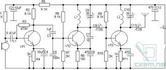
Circuit and assembly: The probe circuit consists of available parts, resistors R1-R7, R12 are selected based on the current consumption of your LEDs, mine are 300 Ohms, resistor R13 with a power of at least 1 Watt. Transistor VT1 Kt3102 or analogues, emitter BA1 with a built-in sound generator, and not just a speaker, zener diodes VD1, VD2 at the probe input are for protection (it is not recommended to supply more than 32V, otherwise you can burn the probe ). Resistors R8.R9 should be chosen with a smaller tolerance spread % and a power of at least 0.25 Watt, for measurement accuracy! A few words about the firmware, just upload the HEX file and that’s it, you don’t need to flash the fuses, we leave the factory ones (works at a frequency of 1 MHz from the internal oscillator), I made it easier, the speed of the probe is of course a little lower, but it will be much easier, especially for beginners, when programming a microcontroller .
Assembly drawing of the board
View from above:
Side of tracks:
Initially I wanted to make an SMD version, but I ran out of photoresist and so I decided to do it the old fashioned way using an iron and printer, which is why the tracks are so thick). I didn’t take a photo of the board, it became too ugly while it was being tested!
Well, as for assembly, everything is extremely simple, the only thing I can advise during installation is to solder jumpers (6 pieces) first into the board, highlight them in red, mark the positive leg of the BA1 emitter with a + on the board, board size 100x25mm. The HL8 LED can be placed in a convenient place on the case to see the positive indication in the wiring. The archive contains a printed circuit board in TIFF format (the print can be opened with any PDF viewer, DjVu, for example, the free STDU Viewer) and firmware in HEX format!
Happy building, my friends!
List of radioelements
| Designation | Type | Denomination | Quantity | Note | Shop | My notepad |
| IC1 | MK AVR 8-bit | ATmega8 | 1 | Search in the Otron store | To notepad | |
| DA1 | Linear regulator | LM78L05 | 1 | Search in the Otron store | To notepad | |
| VT1 | Bipolar transistor | KT3102 | 1 | Or analogues | Search in the Otron store | To notepad |
| VD1, VD2 | Zener diode | 5v1 | 2 | Search in the Otron store | To notepad | |
| R1-R7, R12 | Resistor | 300 Ohm | 8 | Search in the Otron store | To notepad | |
| R8, R10, R13 | Resistor | 2 kOhm | 3 | Search in the Otron store | To notepad | |
| R9 | Resistor | 12 kOhm | 1 | Search in the Otron store | To notepad | |
| R11 | Resistor | 1 kOhm | 1 | Search in the Otron store | To notepad | |
| C1, C2 | Capacitor | 100 nF | 2 | Search in the Otron store | To notepad | |
| C3 | Capacitor | 10uF*10V | 1 | Search in the Otron store | To notepad | |
| HL1-HL8 | Light-emitting diode | 8 | Any select by current | Search in the Otron store | To notepad | |
| HL9 | Light-emitting diode | 1 | Used from a lighter with a flashlight | Search in the Otron store | To notepad | |
| BA1 | Squeaker | TMB12A05 | 1 | Search in the Otron store | To notepad | |
| Add all | ||||||
Attached files:
- avto.rar (4 Kb)
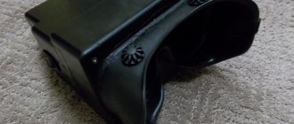
Features of the probe and its operating principle
The continuity probe is structurally a plastic capsule, inside of which a resistor with a high resistance is placed. A metal rod extends from the plastic base, the end of which is used for direct contact with the contacts of electrical equipment. The device shows the presence of voltage; green and red LED lights located on the plastic case act as indicators. The green LED indicates low circuit resistance, the red LED indicates the presence of voltage.
A car test probe, which is essentially a voltmeter, is indispensable when identifying faults in a car's electrical equipment, as well as when installing new electrical equipment on a vehicle.
The diagnostic device makes it possible to determine the integrity of an electrical circuit or a separate section of it, identify locations of broken connections, unreliable contacts, the location of failed parts, as well as identify a number of other damages. To carry out a quick check of current-carrying equipment, the use of a continuity probe is the most rational and expedient solution.
Automotive probe 6-24V 110mm “needle” brass AVTODELO
Automotive tester 6-48V in a FORSAGE bag
Automotive probe for checking the ignition spark JTC
Car probe for checking the ignition spark 0.5m FORSAGE
Automotive probe for checking the ignition spark TEST-M
Car probe 120mm “needle” 6-24V TECHNICIAN
Automotive probe 6-24V FORSAGE
Automotive probe 6-24V 120mm plastic case SPARTA
Automotive probe for checking the ignition spark FORSAGE
Car probe 6-24V reinforced SERVICE KEY
Why is it needed?
A multimeter is a universal electrical measuring instrument for monitoring voltages, currents and resistances in an electrical circuit. Since a modern car is more likely an electronic device than a means of transportation, the presence of a multimeter in its repair kit is necessary, even if the car owner is not an electrical specialist.
You can learn how to use a multimeter in a few minutes. The cost of such a device is small, it can provide disproportionately great help in the event of a malfunction of the vehicle’s electrical equipment.
Currently, automotive multimeters are produced specifically for use by auto electricians and car enthusiasts. They are adapted to measure electrical and other parameters related to the operation of engine systems, battery charge, and vehicle electrical equipment.
Many multimeters are classified as automotive only as a marketing technique. The parameters they measure do not always meet the needs of auto electricians, especially ordinary car enthusiasts.
The use of a continuity probe for testing various types of electrical equipment
Battery check
Using a probe, you can check the presence of voltage at the battery terminals. To do this, using an alligator clip, you need to connect to the battery terminal with the “-” sign, and attach the end of the probe to the terminal with the “+” sign.
Checking the fuse
To check the fuse, touch one end of its terminal to the positive terminal of the battery, and the end of the probe to its second terminal.
Checking the incandescent lamp
To check an incandescent lamp with a continuity probe, place one terminal of its base to the positive terminal of the battery, and attach the end of the probe to the second. When testing a light bulb with two filaments (such as a car headlight bulb), test them one at a time.
Useful do-it-yourself autotester for lamps
To check the functionality of a fuse or lamp, the car enthusiast has to remove them from their sockets. All this takes up quite a lot of precious time. To greatly simplify this task, experienced craftsmen have developed a special tester. It allows you to check lamps without removing them from their sockets. In addition, such a device also has a number of additional, very useful features.
To make a homemade electronic tester you will need two red and green LEDs, a pair of resistors, a round coin cell battery, some stranded wire, an alligator clip and a small plastic box.
The operating principle of the device is very simple. If the lamp or fuse being tested is working, they close the contacts. Current from the battery passes through them and lights up the green LED. If the contact is broken, there will be no green signal. The red LED indicates the presence of external power at the tested object. A detailed diagram of the product can be found on the Internet, on any site dedicated to this topic.
Assembly begins by connecting the parts. For a round battery, it is better to find a special block. Such devices can be found on the remote control of Chinese-made car radios. Two wires are connected to the power source. Then two small holes are drilled in the body of the future tester and LEDs are glued into them. Their legs are connected to resistors.
The tester probe is made from a thick needle from a medical syringe. It is shortened a little and the contact of the resistor from the red LED is inserted into the hole so that it protrudes slightly outward. After this, the base of the needle is glued to the body with a heat gun. All remaining wires are connected according to the diagram. To secure the parts, the internal space in the tester body is filled with hot glue. At the end of the work, close the housing cover.
The tester does not have a switch and is always ready for use. To use it, apply the alligator clip to one fuse contact, and the probe to the other. If the green LED lights up, the part is operational. Lamps in sockets are checked in the same way.
You can check the presence of voltage and its polarity on the wires. To do this, the tester clamp is connected to one contact, and the probe to the other. The red LED that lights up indicates the positive wire on the probe. Indication by a green LED means there is a negative contact on the probe.
Checking a car relay
In addition to the electromagnet winding, an automobile relay also has contacts that, over a long period of operation, can burn out and, as a result, stop switching electrical circuits. Using a continuity probe, you can check both the integrity of the electromagnetic winding and the serviceability of the contacts.
To check the relay winding, you need to attach one of its terminals 85 or 86 to the battery terminal with the “+” sign, and attach the end of the probe to the second terminal. The serviceability of the contacts is determined by touching the terminal of the moving contact 30 to the terminal, and by touching the terminal 87a with a continuity probe.
In the same way, any microswitches and switches are checked.