Hello, dear residents of Datagoria and guests of our cyber city!
Today we are increasingly buying various gadgets, devices, parts, etc. from China. There are a number of reasons for this, the main ones being low cost and wide selection. Not long ago I purchased several devices for my workshop on Aliexpress. But they were all without cases and it was not very convenient to use them in this form. The idea came to combine all the whales in one case, creating one universal device for convenient work. This will be discussed in my article.
Contents
- 1 1. Oscilloscope DSO138
- 2 2. DDS Function Signal Generator Module
- 3 3. Universal tester ESR, MOS/PNP/NPN, L/C/R
- 4 Power supply
- 5 Universal device housing
- 6 Assembly into the housing
- 7 Oscilloscope installation
- 8 Tester installation
- 9 Generator installation
- 10 Food
- 11 Links
- 12 Files
- 13 Total
In the “dormitory” we will put an oscilloscope, a function generator and a universal tester for checking radio components.
DIY electronic (digital) barometers
The factory-calibrated strain gauge and discriminator form the basis of the digital instrument. These and other components can be purchased on Aliexpress, in radio stores, and on the Internet.
A do-it-yourself electronic barometer is assembled on the basis of microsensors and microcircuits (controllers). We will need an MPX 2200 AP strain sensor. At normal pressure 1000 hPa, the voltage at its output is 100 × 0.2 mV = 20 mV. You can also attach a voltmeter to the circuit, but for our situation this is not necessary, since in most cases it is enough to observe changes in the upward/downward direction. We will make the indicator in the form of a scale from several LED elements.
In addition to those indicated, you will need the following elements:
Scheme:
Power is supplied to the sensor from the 9 V crown (pins 1 and 3). To save charge, the circuit contains a regular or micro switch. The pulse from the detector goes to a differential amplifier consisting of 2 operational amplifiers DA2.1 and DA2.2 in a housing, this is an LM324 microcircuit. This element is designed to amplify the amplitude of the strain sensor pulse by 50 times.
R4 is a “variable” for fine adjustment, located between resistors R1 and R2 (the values are the same). Considering the coefficient gain at 1,000 Pa (100 kPa), the output of the amplifier will be 0.2 × 100 × 50 = 1000 mV = 1 V.
With a sensitive voltmeter (digital) with a graduation width of 2 V, it becomes possible to convert the measured voltage taken between outputs 7 and 14 of the LM324 into atm values. pressure To visualize the control, an LM3914 discriminator with 10 comparators is used, each connected by one input to pin (5), the other contacts go to a resistive divider (to its intermediate points).
The potential at the fourth pin indicates the lower threshold of pressure measurement, and the upper one is set by changing the potential with the “variable” R5 at the combined outputs 6 and 7. They need to set a voltage of approximately 1.1 V relative to output 8, thus the upper limit of the atm indication. pressure will be 1060 mbar, which suits us.
How to work with the indicator
The indication has the following order: by rotating the “variable” selector R6, we set the potential at input 5 of the LM3914 controller at which diodes HL5 and 6 turn on. If the measured value increases, then elements from HL7 to HL10 alternately begin to glow, and vice versa, a decrease in pressure, indicating rapid precipitation, is accompanied by a decrease in voltage at the fifth output of the microcircuit. HL4...HL1 will start to turn on one by one downwards.
Board diagram, recommendations
Below is a circuit board template for mounting the board:
It is advisable to take indicator light elements with different colors so that they carry a functional load: white at the bottom, red at the top, and yellow in the middle. The LM circuit for our device works as a DOT point - when pin 9 is deactivated, power is supplied only for the period of pressure indication when the “Measurement” key is pressed. Precise calibration for our purposes is not so important; it is enough to make the sensitivity as high as possible so that the microcircuit responds to the slightest pressure fluctuations.
Digital modules and assemblies on Arduino
Assembly can be done from digital barometric sensor modules. Such devices are made on the basis of an Arduino microcontroller; you also need to purchase a display for such an assembly and all the necessary accompanying parts. Everything you need is available on Aliexpress and similar sites.
Ready-made digital barometric modules with strapping are sold, for example, 32-bit ones, costing about $30.
Let's consider only the basics of such devices, since there are many options and separate articles are devoted to them.
Contact connection diagram (there are different options, so check online, read product instructions, look at diagrams for specific models of microcontrollers and modules):
Homemade digital barometer assembled on a mounting plate:
Options for schematic drawings for assembling a weather station with a barometer on Arduino:
Typically, assemblies on Arduino and similar chips are not just barometers, but mini-weather stations that measure pressure, altitude, temperature, humidity, displaying the clock, date:
↑ 1. Oscilloscope DSO138
I took it here: New Color Screen DSO138 Digital Oscilloscope DIY Kit Circuit Operation Tool high quality free shipping.
The thing is great for simple measurements. Suitable for testing and adjusting audio radio equipment. I won’t describe it; there is a lot of information on the Internet. I can only say that it works very well, stable and correct. Characteristics of DSO138
Analog bandwidth: 0 — 200KHz Sampling rate: 1Msps max Sensitivity: 10mV/Div — 5V/Div Sensitivity error: < 5% Vertical resolution: 12-bit Timebase: 10us/Div — 500s/Div Record length: 1024 points Built-in 1KHz /3.3V test signal Waveform frozen (HOLD) function available Save/recall waveform
↑ 2. DDS Function Signal Generator Module
I ordered it here: DDS Function Signal Generator Module DIY Kit Sine Square Sawtooth Triangle Wave A good generator that can produce signals of different shapes up to 8 MHz (sine wave, rectangle, triangle, saw, etc.). Bipolar power supply. The output signal amplitude is up to 20 Volts with a power supply of ±12 Volts. Display 2x16.
↑ Power supply
I’m making a stationary device for the workshop; I don’t need to move it from place to place; I’ll be powered by 220 Volts. Then you need a small switching power supply that can provide the following voltages: +9 Volts to power the ESR tester; +12 Volts for the oscilloscope; ±12 V and +5 V for generator. I found a switching power supply from a DVD player in my bins, the problem was solved.
From the positive arm of the power supply I supply power to the oscilloscope and from it, through the L7809 (added to the board with two capacitors, seen in the photo in the lower right corner) I supply power to the ESR tester. That's all!
How to make your own humidity sensor
Using a circuit based on a single transistor, you can make a simple humidity sensor. A plate with a sensor that will warn of increased humidity levels. It is made from trimmed fiberglass laminate. The area is divided into two sectors and well tinned.
The essence of the robot: moisture enters the contact of the clinger, they form a rebuff and detect a device that enhances electrical oscillations. And electrically charged particles run through the device.
For robots, an LED kligger and a piezo emitter with a paradigm and a relay winding are suitable. Its contacts will serve as an electrical starter or circuit breaker.
The sensitivity of the device is determined by a construction resistor that responds to any level of passing current.
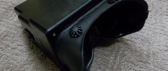
↑ Housing of the universal device
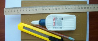
Now the body. It can be made from anything. It's your whim and imagination. To begin with, I placed everything and built it from ordinary cardboard.
Then I built a drawing in AutoCAD for transmission to the factory. Base size 150 mm by 150 mm, height 170 mm. Drawing at the end of the article.
They made me a case from 0.5 mm stainless decorative steel.
PIC16F628A – Page 3 – Meander – entertaining electronics
I once bought an inexpensive floor fan that had two big disadvantages: 1. No remote control. 2. There is no timer to turn off (and I don't want it buzzing all night). So, what is at hand: 1. Microcontroller pic16f628a in a soic package; 2. Two 5V relays for several amperes; 3. Fan; Not bad, it seems like there is somewhere...
Read more
Permanent link to this post:
Most of us spend a lot of time holding a soldering iron. It's no secret that good soldering of components is the key to successful operation of an electronic device. The quality of soldering is determined by its characteristic shine. Grayish and uneven solder joints are a potential cause of poor circuit performance. Another important task is to perform soldering without overheating the components. Good soldering quality is ensured by digital...
Read more
Permanent link to this post: https://meandr.org/archives/10413
I would like to present to your attention a 24 hour timer. A timer was made on the WH-0802 LCD and on the PIC16F628A MK. The timer is very easy to repeat when assembled correctly; no settings are needed. When power is applied, the LCD will display: Using the S1 button, go to the menu and select hours, minutes or seconds. Then use the S2 and S3 buttons to set the desired time...
Read more
Permanent link to this message: https://meandr.org/archives/7222
This craft is a “by-product” after disassembling the FAT16 file system. Everything was done “for ourselves” and is provided “as is”. The main task was to replace the input bell on the UMS8, so battery power was used. Everything was developed on a development board with a more serious microcontroller and was successfully transferred to the 16F628A platform, so the circuit was not drawn separately, due to the lack of...
Read more
Permanent link to this post:
Probably everyone has small relatives - children. The child sooner or later begins to master counting. Training is most effectively carried out in the form of a game. For these purposes, there are various board games in which the number of moves is determined using dice. My little niece shows great interest in electronic toys, especially those with buttons...
Read more
Permanent link to this message: https://meandr.org/archives/3422
↑ Installation of the oscilloscope
The oscilloscope is installed into the device housing using long bolts. The holes on the case match the holes on the board. The bolt is first installed on the housing and tightened tightly with a nut, and then, using two nuts, the installation height of the oscilloscope board is adjusted and the plane of its screen is aligned with the housing. I placed a petal on one of these stands in order to directly remove the minus power of the oscilloscope from the device body.
Accordingly, the minus from the power supply is supplied to the body.
I used external buttons, but initially I cut the case so that instead of the original buttons from the kit, I installed the same ones, but with a 17 mm pusher.
In this case, the buttons will protrude 2-3 mm above the level of the case.
When assembling the oscilloscope and generator boards, I did not solder the buttons, but connected them with wires to external buttons mounted on the case. This is important because desoldering the buttons is not such a simple matter - they snap into the holes of the PCB. It’s even better to connect with wires for testing.
Here you can clearly see how I attached the boards to the case.
In addition to the buttons, I also brought the oscilloscope test generator to the front panel.
Introduction
Breeding chickens requires accuracy in instrument readings. Temperature and humidity values are the most important in such a matter as incubation. In order to monitor the readings qualitatively, you need a device such as a psychrometer. It can be purchased in a store, but not every store has such a device, but you can make a psychrometer with your own hands. I’ll tell you what a psychrometer is and how to make a psychrometer for an incubator with your own hands in this article + thematic video.
↑ Installation of the tester
I made a slight mistake in the dimensions of the installation of external contacts, but I got out of it by sawing off a corner of the board. Lucky. If you repeat, I recommend correcting the position of the holes in the drawing.
External contacts do not come into contact with the device body. To make checking radio elements easier, I made this adapter.↑ Installation of the generator
To reduce the size of the entire device, the board was placed inside the case, connecting everything with wires, and the screen with a cable.
And this is how it looks on the front panel.
↑ Nutrition
Now all that’s left to do is connect the power and solder the oscilloscope input and generator outputs.
Please note that the generator power switch is three-sectional. When turned on, it supplies three voltages at once (described above).
Now we check the functionality of all devices.
We install rubber feet, wooden sides and our device is ready.
To install decorative sidewalls, you can use any available corners.
I used white plastic ones. There are holes in the lower and upper parts for attaching the sides to the body. First, I mark and fasten the corner with a self-tapping screw to the side, and then with a decorative self-tapping screw to the body.
I also install the rubber feet using self-tapping screws.
What is a psychrometer
The “responsibilities” of the device include measuring air parameters. The device is used in poultry farming to accurately determine the humidity value. If the humidity is insufficient, the chicks will not be able to hatch from the shells and all the chicks may be lost at the last stage of incubation. The psychrometer is based on the physical ability of a liquid to evaporate. The result is a difference in temperature between the one shown by the thermometer in a dry environment and the one immersed in a humid environment. Then use the table to find out the exact values.
↑ Links
Oscilloscope DSO138
• New Color Screen DSO138 Digital Oscilloscope DIY Kit Circuit Operation Tool high quality free shipping • Manufacturer's website jyetech.com. Description, manuals in pdf • Assembly and testing (En)
DDS Function Signal Generator Module
• DDS Function Signal Generator Module DIY Kit Sine Square Sawtooth Triangle Wave • Topic on “Soldering Iron”
ESR Meter MOS/PNP/NPN L/C/R
• Mega328 Transistor Tester Diode Triode Capacitance ESR Meter MOS/PNP/NPN L/C/R