The headphone amplifier was created not just as entertainment, but out of real necessity, because you often have to travel by public transport. Unfortunately, listening to music and audiobooks on 32-ohm headphones from a regular mp3 player was pointless. It only produced 2 x 5 mW even at 16 ohms, so at 32 ohms you could hear ambient sounds instead of music.
Stereo sound amplifier on TDA7262
Hi-Fi amplifier for two channels.
This microcircuit has a wide supply voltage range, and the output current reaches 3.5 amperes. A standby function and protection against short circuits and overheating during operation are also available.
Limit characteristics of the microcircuit
| Supply voltage Upit | 25 V |
| Output peak current | 4.5 A |
| Power dissipation Prass | 30 W |
| Working temperature Trab | -20…+85 °C |
Recommendations for properly assembling a sound amplifier with your own hands
A device for enhancing sound quality, assembled at home based on TDA series microcircuits and their analogues, generates a lot of heat. For cooling, you need a radiator grille of a suitable size, depending on the model of the microcircuit itself and the power of the amplifier. There must be a place for it in the case.
The advantage of a self-made device is its low energy consumption, which allows it to be used in cars by connecting to a battery, as well as on the road or at home using a battery. Power consumption depends on the required degree of signal amplification. Some manufactured models require a voltage of only 3 Volts.
We take a serious and responsible approach to assembling a sound amplifier in order to avoid short circuits and failure of components.
Sources
- https://audiogeek.ru/headphone-amp-dual-current/
- https://sdelatlegko.ru/usilitel-zvuka-svoimi-rukami/
- https://baseacoustica.ru/usiliteli/135-svobodu-usham
- https://svoimirykamiinfo.ru/usilitel-zvuka-svoimi-rukami/
- https://usilitelstabo.ru/shemy-usilitelej-dlya-naushnikov.html
Amplifier 50 W
A simple single-channel circuit based on TDA1514.
Chip characteristics
| Parameter | Meaning |
| Upit1 | +10…+30 V |
| Upit2 | -10…-30 V |
| Iout | 5 A |
| Irest | 56 mA |
| Pout | 50 W |
| Rin | 20 kOhm |
| Gain | 30 dB |
| Frequency band | 20-25,000 Hz |
| Harmonic distortion | 0,01 % |
| Rload | 8 ohm |
Pin assignment
| Pin number | Purpose |
| 1 | Non-inverting input |
| 2 | Protection circuit output |
| 3 | Supply Voltage Shutdown Circuit Output |
| 4 | Supply voltage (-27.5 V) |
| 5 | Exit |
| 6 | Supply voltage (+27.5 V) |
| 7 | Power amplifier feedback and correction input |
| 8 | Output shutdown circuit output |
| 9 | Inverting input |
Gain
Gain
The resulting circuit is a non-inverting amplifier. The signal amplification factor is determined by resistors R1 and R2 . Its exact value is determined by the formula:
K= 1+ R2/R1
We will assume that we are applying a signal from the linear output to the input. In this case, the stress force coefficient equal to 3 will be with a good margin. Therefore, we will be equal to three.
The accuracy of resistors R1 and R2 determines how equal the gain of the channels will be. Therefore, it is desirable that resistors have an accuracy of no worse than ±1% . It is not always possible to find a large assortment of resistor values with good accuracy in stores or in home supplies. But in this case, you can get by with resistors of the same value.
So, in the bins of the cabinet, precision resistors of 7.5 kOhm were found, which became resistors R1 . As R2, two 7.5 kOhm resistors were used, which were connected in series. You can do the same thing by connecting in parallel two 15 kOhm resistors as R1 , and one 15 kOhm resistor as R2 .
To change the gain, it is better to change the resistor R2 . For op-amp audio circuits, it is usually recommended to use resistors with a nominal value of 1÷50 kOhm. Any resistor introduces noise into the audio path, and the higher the value of this resistor, the greater the noise it introduces.
TDA8567q 4x25 W
Hi-Fi class bridge amplifier for four channels.
There is protection against short circuit of the output stage and thermal protection with a reduction in output power when overheated. The microcircuit also has protection against voltage fluctuations and a shutdown mode. This microcircuit also has an on/off mode for the input signal (Mute mode), and protection against “clicking” when voltage is applied to the circuit.
Chip characteristics
| Parameter | Meaning |
| Upit | 6-18 V |
| Iout | 7.5 A |
| Irest | 230 mA |
| Pout | 4x25 W |
| Rin | 30 kOhm |
| Gain | 26 dB |
| Frequency band | 20-20000 Hz |
| Harmonic distortion | 0,05 % |
| Rload | 4 ohm |
Pin assignment
| Pin number | Purpose |
| 1 | Supply voltage |
| 2 | Exit 1+ |
| 3 | General |
| 4 | Output 1- |
| 5 | Output 2- |
| 6 | General |
| 7 | Exit 2+ |
| 8 | Supply voltage |
| 9 | Diagnostics |
| 10 | Input 1 |
| 11 | Entrance 2 |
| 12 | General signal |
| 13 | Entrance 3 |
| 14 | Entrance 4 |
| 15 | Mode selection |
| 16 | Supply voltage |
| 17 | Exit 3+ |
| 18 | General |
| 19 | Output 3- |
| 20 | Output 4- |
| 21 | General |
| 22 | Exit 4+ |
| 23 | Supply voltage |
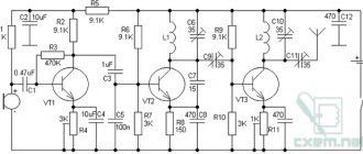
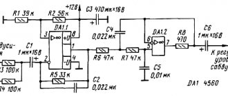
Two-stage ULF with direct coupling between stages
Examples of ULFs with direct connections and minimal selection of operating modes are the circuits shown in Fig. 11 - 14. They have high gain and good stability.
Rice. 11. Simple two-stage ULF for a microphone (low noise level, high gain).
Rice. 12. Two-stage low-frequency amplifier using KT315 transistors.
Rice. 13. Two-stage low-frequency amplifier using KT315 transistors - option 2.
The microphone amplifier (Fig. 11) is characterized by a low level of self-noise and a high gain [MK 5/83-XIV]. An electrodynamic type microphone was used as the VM1 microphone.
A telephone capsule can also act as a microphone. Stabilization of the operating point (initial bias at the base of the input transistor) of the amplifiers in Fig. 11 - 13 is carried out due to the voltage drop across the emitter resistance of the second amplification stage.
Rice. 14. Two-stage ULF with field-effect transistor.
The amplifier (Fig. 14), which has a high input resistance (about 1 MOhm), is made on a field-effect transistor VT1 (source follower) and a bipolar transistor - VT2 (with a common one).
A cascade low-frequency amplifier using field-effect transistors, which also has a high input impedance, is shown in Fig. 15.
Rice. 15. circuit of a simple two-stage ULF using two field-effect transistors.
Stereo amplifier 12 dB
The TDA8199 can be used with both electronic volume controls and simple potentiometers of the appropriate sound class.
Characteristics
| Supply voltage Upit | 10.8 - 13.2 V |
| Current consumption Ipotr | 21 - 28 mA |
| Gain output/input | 12 dB |
| Audio input impedance Rin | 22 - 1000 Ohm |
| Harmonic coefficient Kr | 0,35 — 1 % |
| Audio output impedance Rout | 30 - 1000 Ohm |
| Output noise voltage Uout noise | 30 µV |
Chip Limits
| Supply voltage Upit | 16 V |
| Working temperature Trab | -55…+125 °C |
| Storage temperature | 0…+70 °C |
Step-by-step amplifier assembly process
Having prepared all the necessary tools, understood the diagram and created a layout, you can proceed to the assembly process.
Reference! To improve the sound, they use a wooden chassis rather than a metal one. Plywood would be a good option.
- The first step is to determine the location of the elements. Much attention should be paid to the location of the light bulbs and drilling holes for them.
- All elements that are present in the diagram are arranged according to it.
- First, the filament power buses are applied.
- A filament is connected to each of the lamps.
- Upon completion of these works, passive elements are connected.
This is what concerns the process of assembling a tube amplifier with your own hands.
ULF TDA8198 12 dB
The TDA8198 chip is manufactured in a DIP14 package and is used in high-end equipment.
The dynamic signal level is 90 dB.
There is protection of the output stage from short-circuit and static.
Chip characteristics
| Supply voltage Upit | 10.8 - 13.2 V |
| Current consumption Ipotr | 24 - 32 mA |
| Reference voltage Uref | 6.9 V |
| Output noise voltage Uout noise | 300 µV |
| Harmonic coefficient Kr | 0,3 — 1 % |
| Audio input impedance Rin | 22 kOhm |
| Audio output impedance Rout | 10 - 300 Ohm |
Chip Limits
| Supply voltage Upit | 16 V |
| Working temperature Trab | -55…+125 °C |
| Storage temperature | 0…+70 °C |
↑ Amplifier housing
The housing used is a D-Link switch housing.
Holes are drilled on the side for ventilation. It housed a power supply unit, an ear amplifier and a simple Chinese DAC. The DAC is USB powered, so it works independently of the amplifier. I tried to cover up the logo, but it wasn't worth the effort. The PCB front panel is made using LUT, in a manner described on datagor.ru by comrade AlexD. The original front panel was mercilessly cut with a Dremel. The left LED lights up when the amplifier is turned on, the right one - when the DAC is turned on, that is, when the USB connector is inserted into the computer.
A small toggle switch is used as an input selector; in one position the amplifier is connected to a DAC from Aliexpress on PCM2704, in the other - to the linear input. The digital output of the DAC is located on the rear panel.
You can notice on the front panel there are as many as three amplifier outputs, one 6.3 jack and two 3.5 jacks, all of them are paralleled - in case of a sudden visit from a trio of audiophiles. On the right is the headphone output directly from the DAC board.
If my boards are useful to someone, I recommend increasing the distances between the circuit elements.
ULF TDA8196 12 dB
A simple power amplifier circuit using TDA8196. Scheme for a beginner radio amateur. Doesn't require many parts and is easy to assemble. Miniature bridge low frequency power amplifier with electronic volume control.
There is protection for the output stage against short circuits and thermal protection against overloads. And of course, protection against static. The amplifier can be adjusted either with a potentiometer or with a simple electronic volume control.
Specifications of TDA8196
| Supply voltage Upit | 10.8 - 13.2 V |
| Current consumption Ipotr | 12 mA |
| Reference voltage Uref | 6.6 V |
| Audio input impedance | 10 - 13 kOhm |
| Audio input impedance | 0.2 - 1 kOhm |
| Harmonic coefficient Kr | 0,4 — 1 % |
| Output noise voltage | 40 µV |
Chip Limits
| Supply voltage Upit | 16 V |
| Working temperature Trab | -55…+125 °C |
| Storage temperature | 0…+70 °C |
ULF for headphones. Quality in simplicity, plus silence
I can imagine the simplicity of assembling a headphone amplifier with impedance from 32 ohms to 70 ohms. In this circuit, the background is completely absent, both network and ethereal, despite the proximity of the power transformer to the circuit. For the amplifier, the praised 6s2s triode was chosen, immediately discarding 6n6p, 6n23p and 6n2p.
They say about this lamp that it is the most linear of the driver triodes, as well as its analogue 6s5s with the same pinout and parameters.
Listeners put them in the driver with cool “6s4s” and “2A3” lamps
The input signal must be between 1 Volt and 2 Volt to get sufficient volume from the headphones. The 6S2S triode is designed to amplify voltage in the ULF preliminary stages of high-quality amplifiers. We will try to turn on this lamp in class A with the least amount of parts that distort the sound.
To achieve class A, we need to set the quiescent current to the middle of the linearity of the lamp characteristic, so that the current flows freely in both directions from the given operating point. The setting of the operating point is determined by the voltage on the grid (the operating point of the lamp is marked in red).
For a voltage of 200 volts, the middle of the linear section falls at -3 volts of grid bias. For class A, I choose a fixed grid bias of course, because with automatic bias the voltage on the grid is not stable.
A voltage drop is formed across the cathode resistor, which distinguishes the cathode from the grid by 3 volts while the lamp is standing without load. But under load, the resistor voltage increases, hits the grid and the anode leaves the operating mode point.
Moreover, this voltage fluctuates dynamically repeating the input signal, and does not just deviate 1-2 Volts to the side. Thus, auto-bias distorts the signal. The cathode capacitor spoils the sound because it is an electrolyte, which does not do a good job of transmitting sound.
By switching to a fixed offset, we got rid of unnecessary elements, avoiding deterioration of the sound. A 2.2 µF pass capacitor is needed on the grid so as not to compare the grid with the cathode in voltage. I installed a film “JB” 2.2uF. Also good are FT-3, K-71-7, K-77, K-78 capacitors for sound. The sound passes through a variable resistor, one film capacitor, is amplified and immediately goes to the earphone.
There is no error in this diagram. Below at the end is a diagram without abbreviations, such as “Grounding”, although people are not accustomed to looking at drawn wires intertwined with each other. You will still have to solder the "surface mount". We connect the anode of the lamp through headphones to the plus of the capacitor, which has 200 volts. On headphones at 32 Ohms, the voltage drops to 0.4 Volts, but the current remains 9mA. With such low voltage and low current, the headphones do not burn or heat up. It’s even better to connect high-impedance 50ohm or 70ohm headphones.
At voltages from 12 to 100 volts, the lamps sound the same and are not colorful. Any lamp: 6n6p, 6n2p, 6n23p, 6n8s, 6s3p, 6s19p has not yet given 200 volts - the sound is not the same. I was afraid of burning my headphones with high voltage, but everything works and I listened for several days with 32 ohm headphones. At different volumes, all frequencies are the same - and the bass does not disappear, the high frequencies do not scream, and the mids are not hidden or stick out.
In circuits where the anode is loaded onto a resistor and then transferred through the electrolyte to the headphones, all the power goes to the resistor, leaving the headphones with screaming high and mid frequencies and weak low frequencies. The sound is also distorted by the electrolyte.
And the transformer is the biggest distortion. This option does not work for headphones.
Here all the power goes to the headphones. Nothing spoils the frequency response of beautiful music - not the output transformer, not the electrolyte capacitor, not the anode resistor, which cancels half of the spectrum.
This circuit may seem confusing due to the fixed offset. Fixed bias is a variable resistor with a capacitor, look closely, nothing complicated. Correct power distribution and correct connection of the input signal eliminates the background completely, and the capacitor capacity of 470 microfarads helps to cover all the imperfections with the background. Instead of reading forums, shielding wires, installing kenotrons and chokes in the power supply, figure out this circuit. It is not necessary to ground and connect the negative to the amplifier case, shield the transformer and twist the filament wires into a twisted pair or take the middle point from the filament to the ground.
The bias for the lamp is taken from the 6.3 volt filament winding, rectified and adjusted by a voltage divider minus 2 volts. A 10 kilo-ohm variable resistor acts as a divider. The ends of the resistor from plus to minus of the capacitor are soldered directly, and the middle terminal of the resistor goes to the lamp grid through 470 kilo-ohms. The capacitor responsible for the bias is connected plus or minus the capacitor that powers the lamp anode. Measure the grid voltage between the cathode and the grid. (pins 8 and 5)
The complete circuit is mono. This shows the correct power, input and load connections. The first capacitor (closer to the diode bridge) is common to the two channels; two 500 ohm 1 W resistors go from it to the 470 μF 400 V anode capacitors.
Consider the power supply scheme
All shock currents from the diode bridge are absorbed by capacitor C1.
The ripple filter R1 smoothly transfers current to capacitor C2 without passing shock currents. This is a technique against the network background.
The power supply for the stereo circuit is shown in the figure below.
The power transformer must have a winding voltage of: 6.3V not less than 0.6A 140V not less than 70mA (after rectification it will be 190 volts)
List of radioelements
| Designation | Type | Denomination | Quantity | Note | Shop | My notepad |
| Scheme 1. | ||||||
| Radio tube | 1 | Search in the Otron store | To notepad | |||
| Capacitor | 1 | Search in the Otron store | To notepad | |||
| Electrolytic capacitor | 1 | Search in the Otron store | To notepad | |||
| Resistor | 1 | Search in the Otron store | To notepad | |||
| Speaker | 1 | Search in the Otron store | To notepad | |||
| power unit | 200 V | 1 | Search in the Otron store | To notepad | ||
| Scheme 2. | ||||||
| Radio tube | 1 | Search in the Otron store | To notepad | |||
| Capacitor | 2 | Search in the Otron store | To notepad | |||
| Electrolytic capacitor | 1 | Search in the Otron store | To notepad | |||
| Resistor | 2 | Search in the Otron store | To notepad | |||
| Speaker | 1 | Search in the Otron store | To notepad | |||
| power unit | 200 V | 1 | Search in the Otron store | To notepad | ||
| Scheme 3. | ||||||
| Radio tube | 1 | Search in the Otron store | To notepad | |||
| Capacitor | 1 | Search in the Otron store | To notepad | |||
| Electrolytic capacitor | 1 | Search in the Otron store | To notepad | |||
| Resistor | 2 | Search in the Otron store | To notepad | |||
| Speaker | 1 | Search in the Otron store | To notepad | |||
| power unit | 200 V | 1 | Search in the Otron store | To notepad | ||
| Scheme 4. | ||||||
| Radio tube | 1 | Search in the Otron store | To notepad | |||
| Capacitor | 1 | Search in the Otron store | To notepad | |||
| Electrolytic capacitor | 2 | Search in the Otron store | To notepad | |||
| Resistor | 1 | Search in the Otron store | To notepad | |||
| Variable resistor | 1 | Search in the Otron store | To notepad | |||
| Speaker | 1 | Search in the Otron store | To notepad | |||
| Scheme 5. | ||||||
| Radio tube | 1 | Search in the Otron store | To notepad | |||
| Capacitor | 2.2 µF | 1 | Search in the Otron store | To notepad | ||
| Electrolytic capacitor | 470 µF | 1 | Search in the Otron store | To notepad | ||
| Electrolytic capacitor | 470 µF 400 V | 2 | Search in the Otron store | To notepad | ||
| Resistor | 500 Ohm | 1 | 1 W | Search in the Otron store | To notepad | |
| Variable resistor | 10 kOhm | 1 | Search in the Otron store | To notepad | ||
| Variable resistor | 100 kOhm | 1 | Search in the Otron store | To notepad | ||
| Resistor | 470 kOhm | 1 | Search in the Otron store | To notepad | ||
| Speaker | 1 | Search in the Otron store | To notepad | |||
| power unit | 200 V, 8 V | 1 | Search in the Otron store | To notepad | ||
| Scheme 6. | ||||||
| Radio tube | EF95 | 2 | Search in the Otron store | To notepad | ||
| Electrolytic capacitor | 10 µF | 2 | Search in the Otron store | To notepad | ||
| Resistor | 10 kOhm | 2 | Search in the Otron store | To notepad | ||
| Telephone | 2 | Search in the Otron store | To notepad | |||
| L, R | Input connector | 2 | Search in the Otron store | To notepad | ||
| power unit | 12 V | 1 | Search in the Otron store | To notepad | ||
| Scheme 7. | ||||||
| VL1 | Radio tube | 6N6P | 1 | Search in the Otron store | To notepad | |
| C1 | Capacitor | 4.7 µF | 1 | Search in the Otron store | To notepad | |
| C2 | Capacitor | 4700 µF | 1 | Search in the Otron store | To notepad | |
| C3 | Capacitor | 470 µF | 1 | Search in the Otron store | To notepad | |
| R1 | Resistor | 22 kOhm | 1 | Search in the Otron store | To notepad | |
| R2 | Resistor | 86 Ohm | 1 | Search in the Otron store | To notepad | |
| R3 | Resistor | 3.6 kOhm | 1 | Search in the Otron store | To notepad | |
| Rn | Load resistance | 3G | 1 | Search in the Otron store | To notepad | |
| G1 | Audio source | 1 | Search in the Otron store | To notepad | ||
| E1 | Battery | 220 V | 1 | Search in the Otron store | To notepad | |
| Scheme 8. | ||||||
| Radio tube | 5687WB | 1 | Search in the Otron store | To notepad | ||
| Electrolytic capacitor | 100 µF | 4 | Search in the Otron store | To notepad | ||
| Resistor | 110 Ohm | 2 | Search in the Otron store | To notepad | ||
| Resistor | 3.6 kOhm | 2 | Search in the Otron store | To notepad | ||
| power unit | 12 V | 1 | Search in the Otron store | To notepad | ||
| Scheme 9. | ||||||
| V1, V2 | Radio tube | 6ZH1P | 2 | Search in the Otron store | To notepad | |
| C1 | Electrolytic capacitor | 10 µF | 1 | Search in the Otron store | To notepad | |
| C2, C6 | Capacitor | 0.022 µF | 2 | Search in the Otron store | To notepad | |
| C3 | Capacitor | 0.1 µF | 1 | Search in the Otron store | To notepad | |
| C4 | Electrolytic capacitor | 20 µF | 1 | Search in the Otron store | To notepad | |
| C5 | Capacitor | 1 µF | 1 | Search in the Otron store | To notepad | |
| R1 | Resistor | 240 kOhm | 1 | Search in the Otron store | To notepad | |
| R2 | Resistor | 560 Ohm | 1 | Search in the Otron store | To notepad | |
| R3 | Resistor | 470 kOhm | 1 | Search in the Otron store | To notepad | |
| R4 | Resistor | 3 MOhm | 1 | Search in the Otron store | To notepad | |
| R5 | Variable resistor | 500 kOhm | 1 | Search in the Otron store | To notepad | |
| R6 | Resistor | 1.5 kOhm | 1 | Search in the Otron store | To notepad | |
| Tr1 | Output transformer | 1 | Search in the Otron store | To notepad | ||
| Ls1 | Speaker | 1 | Search in the Otron store | To notepad | ||
| power unit | 125 V | 1 | Search in the Otron store | To notepad | ||
| Scheme 10. | ||||||
| Radio tube | 1 | Search in the Otron store | To notepad | |||
| Diode | 8 | Search in the Otron store | To notepad | |||
| Capacitor | 1 | Search in the Otron store | To notepad | |||
| Electrolytic capacitor | 3 | Search in the Otron store | To notepad | |||
| Resistor | 2 | Search in the Otron store | To notepad | |||
| Variable resistor | 2 | Search in the Otron store | To notepad | |||
| Speaker | 1 | Search in the Otron store | To notepad | |||
| Transformer | 140 V, 6.3 V | 1 | Search in the Otron store | To notepad | ||
| Scheme 11. | ||||||
| Radio tube | 6С2С | 1 | Search in the Otron store | To notepad | ||
| Diode | 8 | Search in the Otron store | To notepad | |||
| Capacitor | 2.2 µF | 1 | Search in the Otron store | To notepad | ||
| Electrolytic capacitor | 470 µF 25 V | 1 | Search in the Otron store | To notepad | ||
| Electrolytic capacitor | 470 µF 400 V | 2 | Search in the Otron store | To notepad | ||
| Resistor | 500 Ohm | 1 | 1 W | Search in the Otron store | To notepad | |
| Variable resistor | 10 kOhm - 50 kOhm | 1 | Search in the Otron store | To notepad | ||
| Variable resistor | 100 kOhm | 1 | Search in the Otron store | To notepad | ||
| Resistor | 470 kOhm | 1 | Search in the Otron store | To notepad | ||
| Terminal clamp | 2 | Search in the Otron store | To notepad | |||
| Speaker | 1 | Search in the Otron store | To notepad | |||
| Transformer | 140 V. 6.3 V | 1 | Search in the Otron store | To notepad | ||
| Scheme 12. | ||||||
| Radio tube | 1 | Search in the Otron store | To notepad | |||
| Diode | 4 | Search in the Otron store | To notepad | |||
| C1, C2 | Capacitor | 2 | Search in the Otron store | To notepad | ||
| R1 | Resistor | 1 | Search in the Otron store | To notepad | ||
| Speaker | 1 | Search in the Otron store | To notepad | |||
| Scheme 13. | ||||||
| Radio tube | 2 | Search in the Otron store | To notepad | |||
| Capacitor | 2.2 µF | 2 | Search in the Otron store | To notepad | ||
| Electrolytic capacitor | 470 µF | 1 | Search in the Otron store | To notepad | ||
| Electrolytic capacitor | 470 µF 400 V | 3 | Search in the Otron store | To notepad | ||
| Resistor | 500 Ohm | 2 | 1 W | Search in the Otron store | To notepad | |
| Variable resistor | 100 kOhm | 2 | Search in the Otron store | To notepad | ||
| Resistor | 470 kOhm | 2 | Search in the Otron store | To notepad | ||
| Variable resistor | 1 | Search in the Otron store | To notepad | |||
| Speaker | 2 | Search in the Otron store | To notepad | |||
| power unit | 200 V, 8 V | 1 | Search in the Otron store | To notepad | ||
| Add all | ||||||
Tags:
- ULF
TDA7265 and two inclusion options
There are two options for turning on the microcircuit.
- Large power range (+-25V);
- Bipolar power supply circuit;
- Power 2x25 W
- There is a silent mode and a standby function;
- Thermal protection against overheating during amplifier operation;
- There is short-circuit protection.
Bridge version of the amplifier on TDA7265
Chip characteristics
| Supply voltage Upit | 25 V |
| Output voltage in idle mode | 80 - 130 mV |
| Current consumption in idle mode Ipotr | 65 - 120 mA |
| Bias current at the non-inverting input Ibias | 500 nA |
| Output power Pout | 20 - 25 W |
| Harmonic coefficient Kr | 0,01 — 0,7 % |
| Gain (Open Loop) | 80 dB |
| Input resistance Rin | 15 - 20 kOhm |
| Shutdown temperature | 145 °C |
Limit parameters of the microcircuit
| Supply voltage Upit | 25 V |
| Output peak current | 4.5 A |
| Power dissipation Prass | 30 W |
| Operating temperature Trab | -20…+85 °C |
| Storage temperature Tstore | -40…+150 °C |
Headphone amplifier circuit
Where this circuit came from and why each specific part was needed was described in detail in the article: Diagram of a headphone amplifier using an op-amp with double the output current .
Bridge to TDA7240
A miniature but quite powerful low-frequency power amplifier, made using a bridge circuit.
The amplifier has:
- Protection of the output stage from short circuit;
- Thermal protection in case of overload;
- Reliable protection against surges up to 28 V.
Chip characteristics
| Upit | 6 - 18 V |
| Iout max | 4.5 A |
| Irest | 150 mA |
| Pout | 20 W |
| Rin | 50 kOhm |
| Gain | 40 dB |
| Frequency band | 30 - 25 kHz |
| Harmonic distortion | 0,5 % |
| Rload | 4 ohm |
Pin assignment
| Pin number | Purpose |
| 1 | Distortion Compensation Circuit Output |
| 2 | Output of correction scheme |
| 3 | Entrance |
| 4 | General |
| 5 | Output 1 |
| 6 | Supply voltage |
| 7 | Exit 2 |
Scheme two, advanced
A headphone amplifier circuit called “Volume and tone control unit for stereo headphones” caught my eye. (Author - Andrzej Kosminski, Hobby Elektronik, No. 2/2000, pp. 48–49). The volume and tone controls themselves are made on the A1 microcircuit - TDA1524A in a typical connection circuit. (This was written in the magazine; in the original description of the microcircuit, the circuit is slightly different. But here the circuit is presented in its “published” form).
A “powerful” amplifier capable of driving low-impedance headphones is assembled on the dual operational amplifier A2.
Depth of volume control (R2) from –80 to +21 dB, bass tone (R4) +/- 12 dB at a frequency of 100 Hz, treble tone (R5) +/- 10 dB at a frequency of 10 kHz.
The maximum input voltage is no more than 2.5 Volts, supply voltage 12 Volts, current consumption 40 mA. The adjusting resistors should be 47 kOhm with a linear dependence of the change in resistance on the angle of rotation of the engine (the so-called group “A”).
There shouldn't be any difficulties in manufacturing. If you want to power the amplifier from a +12 Volt source from the computer's power supply, you will have to take measures to protect against interference in the power circuits (in the same way as car radio manufacturers do - they install special filters).
Fans of shooting games can limit themselves to these designs, but music lovers are encouraged to read the text further.
ULF circuit on TDA7236
The microcircuit is in a minidip (4+4) package.
Chip characteristics
| Supply voltage Upit | 1.8 - 24 V |
| Current consumption with idle mode Ipotr | 5 mA |
| Output power Pout | 1.7 W |
| Harmonic coefficient Kr | 0,3 — 1 % |
| Gain (closed loop) | 38 dB |
| Input resistance Rin | 100 kOhm |
Limit parameters
| Supply voltage Upit | 28 V |
| Output current Iout | 1 A |
| Power dissipation Pdis | 500 mW (SZIP package), 800 mW (SSOP package) |
| Temperature Tb | 40…+150 °C |
↑ Settings
R23 - balancing, i.e. setting “0” at the output.
R15 and R14 set the required quiescent current. With the indicated ratings it is about 100...120 mA. If you need a different quiescent current, you need to proportionally reduce or increase them. If there is a generator and an oscilloscope, then the compensation adjustment is performed by selecting R19 or R20. If not, well, okay, and it will be very good.
“Radio” 1989/12, V. Korol. UMZCH with compensation for the nonlinearity of the amplitude characteristic ... Next, by connecting the equivalent of a load to the output of the amplifier with a variable resistor R23, ensure that there is no constant voltage across the load. Then, by applying a sinusoidal signal with a frequency of 5...8 kHz to the amplifier input, you need to estimate the threshold saturation level of the amplifier using an oscilloscope or an AC voltmeter connected to its output. After this, it is recommended to reduce the input signal to a level of 0.7 from saturation (half power level) and use resistor R19 or R20 to eliminate the constant component (according to the reading) of the microammeter that arose from the quadratic detection of the signal by second-order nonlinearity elements. The experiment showed that this method of amplifier linearization provides fairly high accuracy.
That is, we need to apply this method of adjusting compensation in the realities of our circuit. You can use a sound card + software as a generator, a PK as an oscilloscope, you will also need a device in microampere measurement mode, for example, Ts4315 - 50 m kA.
My supply transformer is TP-20-14, it produces 2×9 V AC. The bipolar stabilizer on LM317/337 produces ±7 V, there is almost no voltage reserve. It will be necessary to do something about this, since when the network voltage is reduced, a hum occurs - the stabilizer leaves the stabilization mode. Otherwise everything is fine.
Amplifier based on TDA7052
Used in portable audio equipment
An amplifier assembled according to this scheme has a number of advantages:
- No external elements needed;
- Minimal interference when turning on and off;
- Sufficiently high stability of operation when amplified;
- Low power consumption;
- No need for an additional radiator
- There is short-circuit protection.
Chip characteristics
| Supply voltage Upit | 3 - 18 V |
| Current consumption in idle mode Ipotr | 4 - 8 mA |
| Gain factor Kusil | 38 - 40 dB |
| output power | 1.2 W |
| Harmonic coefficient Kr | 0,2 — 1 % |
On a laptop
In order to amplify the sound signal, you must purchase the following components:
- Capacitor n/a 0.1 uF 2 pcs
- Capacitor n 100.220, 470 uF 1 pc.
- Fixed resistor 10, 4.7 Ohm, 1 pc.
- Switch.
- Speaker connector.
There are many assembly schemes that are essentially no different. They can be downloaded from the Internet. After everything is connected, it is necessary to make a reliable case in which there will be holes for cooling the radiator.
A pair of amplifiers on the TDA7050 chip
The supply voltage is only 1.6 V and this circuit is excellent for operation on batteries and rechargeable batteries.
The circuits are simple enough to be assembled by novice radio amateurs. It can also be assembled on a breadboard.
Bridge version of the microcircuit amplifier
Advantages of the microcircuit:
- A small number of external elements necessary for the operation of the microcircuit;
- Low current consumption;
- Gain 26 dB;
- Floating differential input;
- The chip has stereo and bridge modes.
Chip characteristics
| Supply voltage (Upit) | 1.6 - 6 V |
| Current consumption in idle mode (I consumption) | 3.2 mA |
| Output power in bridge mode | 140 mW |
| Output power in stereo mode | 75 mW |
| Channel Separation | 40 dB |
Source of schematics
S. R. Bashirov, A. S. Bashirov Modern integrated amplifiers
Specifications
- Supply voltage: 3 - 12 V
- Power consumption: 10 mA / 3 V - 35 mA / 12 V (stereo)
- Output power: 300 mW
This headphone amplifier was built many years ago. And time has shown that this simple circuit is very reliable, it is difficult to burn, it has great power, excellent sound quality, consists of several simple parts and, importantly, consumes very little energy. With two AA batteries, the ULF can work for a very, very long time.
Such a convenient amplifier can find a variety of applications. For example, it can be used as a general purpose stereo amplifier for devices such as iPods, radios, CD players, computers, DVD players, televisions and so on. Or as an excellent audio amplifier for electric guitars, microphones, or as an audio tester.
The sound is really great and there is no shortage of bass. There is a mono version without a potentiometer. The goal was to get the smallest possible board without jumpers or SMD elements.
Transistor mono amplifier circuit
Despite its simple design, the amplifier behaves like a high-class pure transistor ULF. After a few minutes of playback, the details warm up and a little bass is added.
Appearance and design of a single-board 2-channel class AB amplifier based on the TDA2822 chip
Let's look at the amplifier board from different angles (click to enlarge, opens in a new window):
As you can see, the kit even includes a knob for the variable volume resistor.
The input signal is supplied through a socket for a three-pin connector - a 3.5 mm jack.
Next angle:
All external connections, except for the input audio signal, are made without soldering - using screw terminal blocks, which is very convenient.
Next is the top view:
Here you can see that there are really very few details.
And even here, four details are not entirely mandatory; These are two resistor dividers that are installed immediately after the volume control.
A special feature of the mechanical design is the presence of only one screw hole for securing the board. But this is already from the “better than nothing” series. 
Another top view - under “sliding” lighting, so that the chip markings can be seen:
Reverse side of the board:
In the next chapter we’ll look at what’s what and why on this amplifier board.
Circuit design of a single-board stereo headphone amplifier based on the TDA2822 chip
Let's look again at the amplifier board vertically from above:
With the exception of the input circuit, the board corresponds to the typical circuit shown in the datasheet:
As for the input circuit, it includes a variable volume control resistor with a nominal value of 50K; and behind it come voltage dividers consisting of resistors 22K 1% and 1.5K 1%.
In total, the division coefficient is (22+1.5)/1.5 = 15.67.
Accordingly, the gain of the entire board at the maximum position of the volume control will be 89.12/15.67 = 5.69; where 89.12 is the gain of the microcircuit itself (39 dB, converted to “folds”).
During testing, the calculated gain was confirmed with good accuracy.
Let's return to the input circuit.
The value of the electrolytic capacitors connected to pins 5 and 8 of the microcircuit is 10 μF (and not 100, as indicated in the diagram; but this is acceptable here).
The rating of the power supply blocking capacitor is 470 µF * 16 V, which we fully approve of.
At the output, RC circuits C6R3 and C7R4 serve to prevent self-excitation of the amplifier.
Here, in fact, is the whole scheme.
There is also an option in the datasheet to enable this two-channel microcircuit in single-channel bridge amplifier mode (for a stereo amplifier, two microcircuits will be required).
But such a circuit is not suitable for working with standard headphones with three wires (common ground); it can only work with independent speaker connections.
Important note: the board does not have a “foolproof” diode in the power circuit, and therefore the polarity of the power supply should never be reversed!!!