Simple stable radio microphone
I propose a circuit for a very stable radio microphone. The creation of this circuit was prompted by the need for a high-quality beetle, with a stable frequency that does not go away when a person approaches or the device moves. As a result, this scheme was developed and assembled. Even if you turn the device in your hands, twist and untwist the antenna, the frequency does not go away at all. How to achieve stability will be discussed below.
So, the distinctive qualities of this radio microphone: - adjustable sound sensitivity - extremely stable operation - adjustable power
Characteristics: Power: 30-300mW Supply voltage: 3-15V Range: 70-140MHz
Description of the circuit operation
Through R1, power is supplied to the electret capsule, then with the help of C1, the useful signal is separated from the constant component of the power supply and goes to the base VT1. VT1 contains an ultrasonic sounder, which is necessary for pre-amplification of the signal from the microphone. An ordinary cascade with a common emitter, in which R3 sets the bias to the base, and R2 is the load. R4 limits the cascade current, which is necessary to adjust the cascade gain, and C4 shunts it with alternating current, that is, passing only the useful signal. R5 limits the current of the low-frequency part, and together with C2 acts as a G-filter that protects the circuit from self-excitation. Through C3, the signal goes to the VT2 base, on which the HHF is performed. R6 and R7 set the base bias, R8 limits the cascade current. C5 bypasses the base to a common output, which is why such a cascade is called a cascade with a common base. C7 creates feedback, and C8 bypasses R8, allowing the RF signal to pass freely. A parallel oscillatory circuit is assembled at L1 and C6, on which the generation frequency depends. Through C9, the HF signal has already been generated by VT2, and modulated by the LF signal from VT1, it reaches the VT3 base, on which the UHF is assembled. R9 and R10 set the offset based on VT3. R11 limits the cascade current and allows you to change the output power of the device. L2 and C10 form an oscillatory circuit similar and resonant to the HHF circuit. Capacitor C11 is a separation capacitor between the UHF and the antenna. C12 bypasses the circuit via HF, which prevents self-excitation at high frequencies.
Elements used and interchangeability
VT1-9014; VT2, VT3- 9018. L1, L2- 6 turns of 0.5mm wire, on a frame with a diameter of 3mm. Antenna - a piece of wire 20-60cm. All resistors are 0.125-0.5W. Capacitors C1, C2, C3 and C4 are electrolytic, the rest are ceramic.
Power source: any voltage 3-15V, in my case 2 lithium tablets of CR2032 size. VT1 can be replaced with a KT315, BC33740 transistor or almost any low-power NPN structure transistor with sufficient gain. VT2, VT3 can be replaced with a KT368 transistor, or any other low-power ones with a cutoff frequency of at least 200 MHz.
Settings
The setup comes down to setting the microphone sensitivity, setting the frequency and tuning the UHF circuit to resonance. Using R4, it is necessary to adjust the sensitivity of the ULF cascade so that a close conversation does not cause overload, and the sensitivity is still sufficient to hear it within a room or apartment.
Using C6, a rough choice of frequency is made; for more precise adjustment, it is necessary to change the geometry of L1 by stretching the turns. Using C10, the UHF circuit must be adjusted to resonate with the carrier. The output power depends on the value of R11.
Assembly
Assembly must be carried out following the basic rules of RF installation - shorten the terminals of the elements as much as possible, exclude large and thick tracks and contacts capable of stray capacitances, apply shielding.
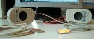
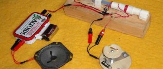
In my assembly version, the device was assembled on double-sided foil fiberglass. On one side there is a direct surface-mount circuit, on the second there are blocks for 2 lithium tablet batteries of the CR2032 type. One of the features is the use of the key as a power switch. In order to activate the device, you need to insert the key into the connector; this was done for convenient and reliable activation.
The photo shows a beetle assembled and covered with a thermal tube, as well as a key. A piece of tin was soldered to the end of the antenna to make it easier to attach the end of the antenna.
You can download the printed circuit board in Sprint-Layout format below
Methods for increasing the stability of radio microphones
Many novice radio amateurs who decide to try simple and interesting bug circuits often cannot configure the circuit after assembly. And when faced with a problem, at best they pester you on the forums, at worst they abandon the idea. One of the most common problems in such designs is unstable operation and frequency drift.
First of all, we will consider the factors influencing the operation of the main frequency generator, on which the stability of the carrier depends. Most “bugs” are created using a three-point type HHF on a single transistor. Let's consider several factors influencing the stability of generation.
1. The case in which the antenna clings directly to the MHF and the influence of the antenna.
An antenna connected through a capacitor or inductive coupling directly to the MHF essentially becomes a receiver, and not just a transmitter, because its capacity, as well as its location in space and extraneous HF currents induced into it are transmitted to the MHF circuit and have a great effect on its operation. It's the same as connecting a source of interference to the HHF.
The solution to this problem is a simple UHF cascade, or a repeater, that is, a UHF with practically no gain, necessary only to limit the UHF from feedback from the antenna. An example of the simplest low-power UHF is given below.
2. Oscillatory circuit. The quality of the oscillating circuit coil also influences the stability of operation. A coil made of too thin wire, which does not have a housing and is not filled with anything, will change its geometry when there is a physical impact on the device, that is, during movements and other vibrations. A change in geometry will cause a change in inductance, which in turn will cause a change in frequency.
The solution to this problem is to glue the coils, wind them on a frame, and wind the coils with thicker wire.
3. Nutrition. The operation of the device in general always depends on the power source. Over the course of their operation, batteries will change their voltage quite significantly, which will also be expressed by a gradual decrease in frequency. The solution is to use stabilizers and circuit solutions that are not strongly dependent on the power source.
4. Shielding. When metal or other electrically conductive objects approach, they affect the inductive and capacitive environment of the circuit. For example, metal shielding passing next to the oscillatory circuit will affect its inductance, increasing it and decreasing the frequency. Permanent shielding with an unchangeable geometry that has a constant impact is not a problem; on the contrary, it protects the device from external influences. Otherwise, when the device is placed on a metal base, it may interfere with operation. The solution is to use shielding, using a thick plastic case that limits the minimum possible distance to the board.
List of radioelements
| Designation | Type | Denomination | Quantity | Note | Shop | My notepad |
| VT1 | Bipolar transistor | 9014 | 1 | KT315, BC33740 | Search in the Otron store | To notepad |
| VT2, VT3 | Bipolar transistor | 9018 | 2 | KT368 | Search in the Otron store | To notepad |
| C1 | Electrolytic capacitor | 0.47 µF | 1 | Search in the Otron store | To notepad | |
| C2, C4 | Electrolytic capacitor | 10 µF | 2 | Search in the Otron store | To notepad | |
| C3 | Electrolytic capacitor | 1 µF | 1 | Search in the Otron store | To notepad | |
| C5 | Capacitor | 100 nF | 1 | Search in the Otron store | To notepad | |
| C6, C9-C11 | Trimmer capacitor | 35 pF | 4 | Search in the Otron store | To notepad | |
| C7 | Capacitor | 15 pF | 1 | Search in the Otron store | To notepad | |
| S8, S12 | Capacitor | 470 pF | 3 | Search in the Otron store | To notepad | |
| R1, R2, R5, R6, R9 | Resistor | 9.1 kOhm | 5 | Search in the Otron store | To notepad | |
| R3 | Resistor | 470 kOhm | 1 | Search in the Otron store | To notepad | |
| R4 | Trimmer resistor | 3 kOhm | 1 | Search in the Otron store | To notepad | |
| R7, R10 | Resistor | 3 kOhm | 2 | Search in the Otron store | To notepad | |
| R8 | Resistor | 150 Ohm | 1 | Search in the Otron store | To notepad | |
| R11 | Trimmer resistor | 1 kOhm | 1 | Search in the Otron store | To notepad | |
| L1, L2 | Inductor | 2 | Search in the Otron store | To notepad | ||
| Antenna | Wire 20-60cm | 1 | Search in the Otron store | To notepad | ||
| Microphone | Electret | 1 | Search in the Otron store | To notepad | ||
| Switch | 1 | Search in the Otron store | To notepad | |||
| Battery | 2xCR2032 | 1 | Search in the Otron store | To notepad | ||
| Add all | ||||||
Attached files:
- radiomic143.rar (17 Kb)
Tags:
- Radio microphone
- Sprint-Layout
Radio microphone circuit
In fact, the radio microphone itself is not something fundamentally new, but is a compilation of well-known blocks that have proven themselves in practice, namely:
- Microphone amplifier, from Christian Tavernier, assembled on a dual, low-noise op-amp TL082 with the ability to adjust the gain;
- Master oscillator and modulator - built on the basis of the MAX1472 transmitter chip, which has proven itself in “R series” radio microphones;
- UHF transistor BFG540, used in a radio microphone on a PIC controller.
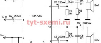
The circuit diagram of the device is simple to the point of disgrace, so please don’t knock it right away:
Radio microphone circuit on two microcircuits
Making a printed circuit board (small digression)
The main difficulty for many beginning radio amateurs in the manufacture of such products is the manufacture of a printed circuit board for a modern element base. Of course, you can order PP in production, but its price will be “golden” given the poorly developed technological base of our enterprises and the desire of businessmen to get 1000% of the profit from any order. Therefore, radio amateurs have to master a variety of methods for producing printed circuit boards at home.
It’s been a couple of years since I switched from the LUT method to manufacturing boards using photoresist technology. With this manufacturing method, the quality of the boards practically depends only on the quality of the pattern that your printer can reproduce. This method is more reliable and effective than LUT, although it requires some initial costs for the purchase of the necessary materials. Beginners are intimidated by the apparent complexity of the technology and the unpredictability of the result. I believe that this is an international conspiracy of capitalists who do not want young talents to develop in our country and global innovations to be born