Laser cutting is the most advanced, but also expensive technology. But with its help you can achieve results that are beyond the power of other metal processing methods. The ability of laser beams to give any material the desired shape is truly limitless.
The unique capabilities of the laser are based on the following characteristics:
- Clear directionality - due to the ideal directionality of the laser beam, the energy is focused at the point of impact with a minimum of losses,
- Monochromaticity - the laser beam has a fixed wavelength and a constant frequency. This allows it to be focused with ordinary lenses,
- Coherence – laser beams have a high level of coherence, so their resonant vibrations increase the energy by several orders of magnitude,
- Power - the above properties of laser beams ensure that the energy of the highest density is focused on a minimal area of material. This allows you to destroy or burn through any material in a microscopically small area.
Design and principles of operation
Any laser device consists of the following components:
- energy source;
- working body that produces energy;
- an optical amplifier, a fiber-optic laser, a system of mirrors that amplify the radiation of the working element.
The laser beam produces precise heating and melting of the material, and after prolonged exposure, it evaporates. As a result, the seam comes out with an uneven edge, evaporating material is deposited on the optics, which reduces its service life.
To obtain smooth thin seams and remove vapors, the technique of blowing melt products from the laser impact zone with inert gases or compressed air is used.
Factory laser models equipped with high-grade materials can provide good indentation rates. But for household use they are too expensive.
Models made at home are capable of cutting into metal to a depth of 1-3 cm. This is enough to make, for example, parts for decorating gates or fences.
Laser cutting of metal
Depending on the technology used, there are 3 types of cutters:
- Solid state. Compact and easy to use. The active element is a semiconductor crystal. Low-power models have quite affordable prices.
- Fiber. Glass fiber is used as the radiation and pumping element. The advantages of fiber laser cutters are high efficiency (up to 40%), long service life and compactness. Since little heat is generated during operation, there is no need to install a cooling system. It is possible to produce modular designs that allow you to combine the power of several heads. The radiation is transmitted via flexible optical fiber. The performance of such models is higher than solid-state ones, but their cost is higher.
- Gas. These are inexpensive but powerful emitters based on the use of the chemical properties of gas (nitrogen, carbon dioxide, helium). With their help you can weld and cut glass, rubber, polymers and metals with a very high level of thermal conductivity.
Driver
Laser power supply must be handled responsibly. As with LEDs, it must be a stabilized current source. On the Internet there are many circuits powered by a battery or accumulator through a limiting resistor. The sufficiency of this solution is questionable, since the voltage on the battery or battery changes depending on the charge level. Accordingly, the current flowing through the laser emitting diode will deviate greatly from the nominal value. As a result, the device will not work efficiently at low currents, and at high currents it will lead to a rapid decrease in the intensity of its radiation.
The best option is to use a simple current stabilizer based on the LM317. This microcircuit belongs to the category of universal integrated stabilizers with the ability to independently set the output current and voltage. The microcircuit operates in a wide range of input voltages: from 3 to 40 volts.
An analogue of LM317 is the domestic chip KR142EN12.
For the first laboratory experiment, the diagram below is suitable.
The only resistor in the circuit is calculated using the formula: R=I/1.25, where I is the rated laser current (reference value).
Sometimes a polar capacitor of 2200 μFx16 V and a non-polar capacitor of 0.1 μF are installed at the output of the stabilizer in parallel with the diode. Their participation is justified in the case of supplying voltage to the input from a stationary power supply, which can miss an insignificant alternating component and impulse noise. One of these circuits, powered by a Krona battery or a small battery, is presented below.
The diagram shows the approximate value of resistor R1. To accurately calculate it, you must use the above formula.
Having assembled the electrical circuit, you can make a preliminary connection and, as proof of the circuit’s functionality, observe the bright red scattered light of the emitting diode. Having measured its actual current and body temperature, it is worth thinking about the need to install a radiator. If the laser will be used in a stationary installation at high currents for a long time, then passive cooling must be provided. Now there is very little left to achieve the goal: focus and get a narrow beam of high power.
Homemade household laser
To carry out repair work and manufacture metal products at home, do-it-yourself laser cutting of metal is often required. Therefore, home craftsmen have mastered manufacturing and successfully use hand-held laser devices.
In terms of manufacturing cost, a solid-state laser is more suitable for household needs.
The power of a homemade device, of course, cannot even be compared with production devices, but it is quite suitable for use for domestic purposes.
How to assemble a laser using inexpensive parts and unnecessary items.
To make a simple device you will need:
- laser pointer;
- battery-powered flashlight;
- CD/DVD-RW writer (an old and faulty one will do);
- soldering iron, screwdrivers.
How to make a handheld laser engraver
Laser cutter manufacturing process
- You need to remove the red diode from the computer disk drive, which burns the disk when recording. Please note that the drive must be a write drive.
After dismantling the upper fasteners, remove the carriage with the laser. To do this, carefully remove the connectors and screws.
To remove the diode, you need to unsolder the diode mountings and remove it. This must be done extremely carefully. The diode is very sensitive and can be easily damaged by dropping it or shaking it sharply.
- The diode contained in it is removed from the laser pointer, and the red diode from the disk drive is inserted in its place. The pointer body is disassembled into two halves. The old diode is shaken out by picking it up with the tip of a knife. Instead, a red diode is placed and secured with glue.
- It is easier and more convenient to use a flashlight as a body for a laser cutter. The upper fragment of the pointer with a new diode is inserted into it. The glass of the flashlight, which is an obstacle to the directed laser beam, and parts of the pointer must be removed.
Laser pointer
When connecting the diode to battery power, it is important to strictly observe the polarity.
- At the last stage, they check how securely all the laser elements are fixed, the wires are connected correctly, the polarity is observed and the laser is level.
The laser cutter is ready. Due to its low power, it cannot be used when working with metal. But if you need a device that cuts paper, plastic, polyethylene and other similar materials, then this cutter is quite suitable.
Gutting a DVD drive or how to make a laser cutter with your own hands
Turn your laser pointer into a cutting laser with a DVD burner emitter! This is a very powerful (245 mW) laser, and it is the perfect size for the MiniMag pointer.
Please note that not all laser diodes (not all DVD or CD-RW models) are suitable for making this laser cutter.
CAREFULLY! As you know, lasers can be dangerous. Never point the pointer at a living creature! This is not a toy and cannot be treated like a regular laser pointer. In other words, don't use it for presentations or playing with animals, and don't let children play with it. This device should be in the hands of a reasonable person who understands and is responsible for the potential hazards posed by the pointer.
Handle laser radiation with extreme caution. Any contact with the eyes, due to refraction in the lens, manages to burn out several cells in the eye. A direct hit will cause loss of vision. The beam reflected from the mirror surface is also dangerous. Absent-minded is not so dangerous, but still does not add sharpness to vision.
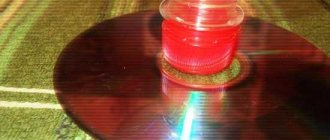
You can conduct interesting experiments with a laser cutter. Lighting matches is not the most effective option. You can burn paper, you can remotely pop balloons at demonstrations. Preferably the ball is dark in color, green or blue; red does not burst.
The focused beam leaves a rather deep groove on the black plastic, and a small spot of white or mirror color appears in the transparent plexiglass at the focal point. If such a diode is attached to the plotter head, then it can be engraved on plexiglass.
The following is detailed information on how to make a laser cutter with your own hands. Be careful and careful!
First, you will need a faulty DVD-RW (with faulty mechanics and not a laser). Although not every DVD can be broken, for example, Samsung is not suitable at all, the diodes there are unpackaged and the crystal is not protected in any way, it is disabled by simply touching the end.
For making a laser cutter with your own hands, LG drives are best suited, only different models have different diodes in power.
The power of the installed diode can be determined by the following characteristic of the drive: you need to look at the speed at which it writes two-layer discs, if at the tenth, then the diode power is one hundred eighty - two hundred, if at the sixteenth - two hundred fifty - two hundred seventy.
If you don’t have a faulty DVD drive, then first try purchasing a separate laser on the radio market. If that doesn’t work, then we buy a faulty DVD from junk dealers.
Next, unscrew the screws from the DVD drive and remove the cover. Below it you will find the laser carriage drive assembly.
Although DVD drives are different, each has two guides along which the laser carriage moves. Remove the screws, release the guides and remove the carriage. Disconnect the connectors and ribbon cables.
Having removed the carriage from the drive, begin disassembling the device by unscrewing the screws. There will be a lot of small screws, so be patient.
Disconnect the cables from the carriage. There may be two diodes, one for reading the disc (infrared diode) and the actual red diode, which is used for burning. You need a second one.
A printed circuit board is attached to the red diode using three screws. Use a soldering iron to CAREFULLY remove the 3 screws.
You can test the diode using two AA batteries, taking into account the polarity. You will have to remove the diode from the housing, which will vary depending on the drive. The laser diode is a very fragile part, so be extremely careful.
This is what your diode should look like after being “released”.
Remove the sticker from the body of the purchased AixiZ laser pointer and unscrew the body into upper and lower parts. Inside the top there is a laser diode (5 mW), which we will replace. I used an X-Acto knife and after two light strikes, the original diode came out. In fact, such actions can damage the diode, but I have managed to avoid this before. Using a very small screwdriver, I knocked out the emitter.
I used some hot glue and carefully installed the new DVD diode into the AixiZ case. Using pliers, I SLOWLY pressed the edges of the diode towards the body until it was flush.
Make sure the polarity of the diode is correct before you install it and connect power! You may need to shorten the wires and adjust the beam focus.
Place the laser pointer in a suitable flashlight with two batteries. Insert the batteries (AA) into place, screw on the top of the flashlight (diffuser), including your new laser pointer! The plexiglass must be removed from the reflector. Attention!! Laser diodes are dangerous, so do not point the beam at people or animals.
How to increase laser power for metal cutting
You can make a more powerful laser for cutting metal with your own hands by equipping it with a driver assembled from several parts. The board provides the cutter with the required power.
The following parts and devices will be needed:
- CD/DVD-RW writer (an old or faulty one will do), with a writing speed of more than 16x;
- 3.6 volt batteries – 3 pcs.;
- 100 pF and 100 mF capacitors;
- resistance 2-5 Ohm;
- collimator (instead of a laser pointer);
- steel LED lamp;
- soldering iron and wires.
You cannot connect a current source to the diode directly, otherwise it will burn out. The diode draws power from current, not voltage.
Laser collimator
The beams are focused into a thin beam using a collimator. It is used instead of a laser pointer.
Sold at an electrical goods store. This part has a socket where the laser diode is mounted.
DIY Laser Pointer
HELLO, DIMON PEOPLE!!! Today, I will tell YOU how to make a powerful laser pointer at home. To do this, we need 17 things: 1- faulty (dead) DVD drive, speed 16-22X (the higher the speed, the more powerful the laser in it) PRICE-50-300R 2- cheap Chinese flashlight (for 3 batteries) PRICE- 50R 3- cheap laser pointer “double-barrel” (laser pointer + LED flashlight) [PRICE-50R 4- soldering iron, power 40W (W), voltage 220V (V) with a thin tip. 5- low-melting solder (type POS60-POS61), pine rosin. 6 - a piece of one-sided fiberglass with dimensions of 35X10mm 7 - ferric chloride (sold in radio stores) price - 80-100 RUR 8 - tools (tweezers, magnifying glass, small screwdrivers, pliers, long-nose pliers, etc.) 9 - these are the terminal lugs (sold in any electrical store) cost from 10-35R 10- tube of super glue 11- alcohol (can be found in a pharmacy) 12- laser printer 13- page of any glossy magazine (necessarily glossy, smooth. You can also use photo paper) 14- electric iron (take at home. Mom, sister, grandmother, wife have not seen it yet) 15-radio components (you can get some from the dead drive itself, in particular Schottky diode, resistors, capacitors) list of parts and their value (ALL SMD PARTS, i.e. for surface mounting (saving space)), the LM2621 R1 chip needs to be selected.. the current on the Laser diode depends on it. I have 78kOhm current 250-300mA NO MORE!!! otherwise it will burn!!! R2 150 kOhm R3 150 kOhm R4 500 Ohm C1 0.1 μF ceramics, for example k10-17 C2 100 μF 6.3 V any C3 33 μF 6.3 V, preferably tantalum. C4 33pF ceramics, for example k10-17 C5 0.1uF ceramics, for example k10-17 VD1 any 3-amp. for example 1N5821, 30BQ060, 31DQ10, MBRS340T3, SB360, SK34A, SR360 L1 in the photo you can see what it looks like... and so, 15 turns on a suitable ferrite ring or frame. You can disassemble either a computer power supply unit, an energy-saving light bulb, or a mobile phone charger, including a car mobile phone charger. All this is not so important, the microcircuit will set everything up as it should. 16-type multimeter DT890G, allowing you to measure capacitance, resistance, voltage and so on. 17- and of course straight HANDS and “friendship with a soldering iron” or a friend who is friends with a soldering iron So, everything is there??? LET'S GET STARTED We take the keychain pointer and disassemble it (CAREFULLY, DO NOT DAMAGE THE INSIDE, we will need them), take out the batteries, and using pliers, carefully swinging them to the sides, pull out the front plastic head (where the flashlight and laser are) Then through the side where this one was (the plug ) we take out the insides, pushing them with a pencil from the side of the battery compartment. Then, very carefully, using a small counter with a flat tip, unscrew the plastic nut in the collimator (the brass tube where the lens and the frameless laser itself are located). We take out the contents (the plastic nut itself, the lens, the spring), warm up the EMPTY collimator with a soldering iron, and disconnect it from the board with the button. We disassemble the drive and take out the carriage of the laser device. EXTREMELY carefully remove the LASER, having previously wrapped the legs of the Laser with wire to prevent static. this is the Laser Diode itself. We take a Chinese lantern and disassemble it. Roughly similar to a flashlight pointer. Now, let’s put all the little things in a safe box, and we’ll make a heat sink for the Laser. We take previously purchased terminals and saw off them piece by piece, so that we get a type of washer equal in length to the length of the collimator, and so that they (the washers fit tightly into each other, including the collimator itself) If they do not fit into each other, we drill out with drills with a diameter of 5.5-12mm for different washers, or we bore. It should look something like this: We push the collimator itself a little further, about 5mm, this is important for fixing the Laser Diode. Yes, we fix the washers themselves with super glue. So, now we mount the Laser Diode by first inserting a 5mm drill into the collimator and pressing the collimator with pliers on the side of the slots where the board was. Solder 2 wires to the LD legs. ATTENTION SOKOLEVKU L.D. We call the device with a multimeter type DT890G (it sounds like a regular diode.) Next, we need to assemble the driver circuit. HERE IS THE DIAGRAM for assembly HERE is an approximate drawing of the conductors on the board (I can send the drawing in a personal message) We transfer the board drawing onto glossy paper with a laser printer (laser-iron method, read on the Internet), we make a board, and we solder the parts onto it. It should look like this: Assembly method, your imagination. I assembled the driver in the battery compartment, in place of the third battery. I used VARTA 800mA/H batteries. I used the lens from a flashlight pointer, but you can also use the original one from the drive, only it has a shorter focal length, you will have to install another spring to prop the lens closer to the Laser Diode. Attention! LASER RADIATION IS EXTREMELY DANGEROUS TO THE EYES! NEVER TURN AWAY PEOPLE OR ANIMALS! 100% LOSS OF VISION! This is the device I came up with: DO NOT turn on the LD itself without a radiator, it gets very hot and will burn out. Set the CURRENT consumption of the Laser Diode to 250-300mA using resistor R1 (it is advisable to temporarily install a 100k resistor, and instead of the Laser Diode (so as not to burn the LD), a chain of 4 KD105 diodes connected in series) Sincerely, T3012, aka KILOVOLT.
Assembly Tips
To check the operation of the driver, use a multimeter to measure the current supplied to the diode. To do this, connect a non-working (or second) diode to the device. For most homemade devices, a current of 300-350 mA is sufficient.
If you need a more powerful laser, the indicator can be increased, but not more than 500 mA.
It is better to use an LED flashlight as a homemade housing. It is compact and convenient to use. To prevent the lenses from getting dirty, the device is stored in a special case.
Important! A laser cutter is a kind of weapon, so it should not be pointed at people, animals, or given to children. Carrying it in your pocket is not recommended.
It should be noted that do-it-yourself laser cutting of thick workpieces is impossible, but it can cope with everyday tasks.
How we made a laser from a DVD-RW drive
Without much prelude, I’ll start with which drive is best to use.
- First, it must be a write drive (RW);
- Secondly, the higher the write speed, the more powerful the laser will be;
- Well, thirdly, the more unnecessary it already is, the more satisfaction you can get from it. I noticed a direct correlation

So, let's select the right drive.
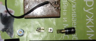
Removing the laser module
We disassemble and get to the laser head.
Remove the laser head.
Our goal is the laser module.
Before removing the module itself, we short-circuit all three of its terminals with a thin copper wire (we took one thread from a stranded one). This is necessary to protect against static.
The laser module can now be removed. It “sits” there quite well, so you need to work hard and balance the efforts between “unbreaking” and “not breaking.”
This is how it should work out somehow.
Circuit assembly
Now let's move on to the diagram. It is necessary to control the laser power. Otherwise it will simply burn out.
We didn’t bother and did a wall-mounted installation.
Nutrition
You need to power it from 3.7V. Mobile phone batteries connected in parallel are ideal for a portable laser.
We used a stabilized power supply.
Warning
You should be warned in advance about the ruthlessness of the laser to the retina.
When working with a laser, you must use special glasses. You may ask why I am writing all this, because no one will do this anyway? Well, what if! Perhaps there will be at least one reasonable person who will wear special glasses when handling a laser. And these lines will save one or even two eyes!
We didn’t have such glasses and we did everything at our own peril and risk. But red glasses, unlike safety glasses, will allow you to better see the laser beam itself. For beauty, you can add smoke, as we did in the intro for the video.
Trial run
Having connected the power, we see a consumption of 200mA and a beam of bright light.
In the dark it works like a flashlight.
Focus lens
The beam turned out to be not “laser” at all. You need a lens to adjust the focal length. For starters, a lens from the same drive is quite suitable. Through the lens it is possible to focus the beam, but without a rigid body the task is tedious.
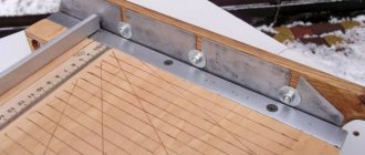
Case manufacturing
I came across a description on the Internet where people used laser pointers or a flashlight as a body. Moreover, there are already lenses there. But, firstly, we did not have a laser pointer of the required size on hand. And, secondly, it would increase the budget of the event. And I already said that for me personally this reduces the pleasure from the result obtained. We started sawing the aluminum profile.
Everything needs to be isolated.Lens
The lens was attached to plasticine to adjust its position.
By the way, this lens works better if it is turned over with the convex part facing the laser diode.
We adjust and get a more or less collected beam.
It's probably possible to fine-tune it, but for us this was enough for the black plastic to start melting.
The match instantly ignited.
This laser would make a great gun for playing toy soldiers.
Video
The video shows the speed of the laser's impact on some materials (a white sheet, writing on paper with a marker, black plastic and black electrical tape, thread, plasticine).
You can subscribe to new HI-TESTING experiments on VKontakte or follow new video stories on the channel’s website.