High voltage converter circuit
Let's assemble everything on a breadboard without soldering.
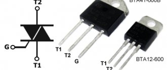
I’ll just show you the work, and if you like it, you can transfer it to a more reliable board and solder all the elements. Connecting a transistor, if anyone doesn’t know. We need to wind the transformer winding. The high-voltage winding will be original. We take a regular, not very thin wire and wind it with 14-16 turns. We will make a tap in the middle of the winding. Now we connect everything to our circuit. The last thing to do is connect the power. Be careful as you are working with high voltage. Do not put your hands near the switched on transformer. Make a distance of approximately 1 cm between the high voltage output of the transformer and the terminals of the other side. And only then serve food. If it sparks, it means the generator is excited and everything works fine. If you will use it for a long time, it is advisable to install the transistor on the radiator. And if the spark is small, then you can increase the voltage to 10 or 15 V.
Video of work
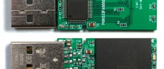
This compact cylindrical converter is capable of delivering up to 400 kV.
It can be used as a shock device to scare away dogs... or people! Also, based on this module, it is possible to create a compact electronic lighter, which is now so popular. This boost converter is capable of punching up to 20 mm of air, which, you see, is quite a lot. The current consumption is quite high, can reach several amperes - stock up on a powerful energy source. With an input voltage of 3-7.2V, this module outputs 200,000V high voltage at some frequency. The converter can be used to demonstrate the action of high voltage, a negative ion generator and for any scientific experiments as a high voltage source. At 4.2 V and an electrode distance of 3 mm, the current consumption was 2.9 A, while the output frequency was very high. At a distance of 23 mm, which is slightly larger than stated at U = 4.5 V, the current came out to 3 A. But this step-up converter could not handle 25 mm, only the contacts sparked. Naturally, the passage of current through the air is accompanied by a loud crackling sound (the greater the distance, the lower the frequency), which, to put it mildly, excites. It is recommended to use two banks of lithium-ion batteries connected in series with a capacity of at least 2000 mA*h or 5-6 NiMH/NiCd rechargeable batteries for power supply. Despite its impressive power, the dimensions of this boost module are more than modest: 24 by 64 mm.
Simple High Voltage Powder Coating Unit
Good afternoon
I wrote about problems with a high-voltage powder coating unit, see Post #7:
In the description of making a spray gun:
in Post #11 Aldar Kose wrote:
at the same time very good I wanted to understand how a 30 kV power supply works.. and how to make it..
Here's what I got.
In those days I did not have the Internet, PCAD and time. I had to quickly come up with something. I think I found an idea in Radio magazine.
I assembled the diagram:
and it worked.
ATTENTION:
The circuit is galvanically connected to the supply network. To ensure correct connection of the phase and neutral wires of the power supply network, there is a power cord with three contacts.
To isolate from the network, you can use a 220V to 220V transformer.
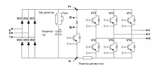
Circuit operation:
When the unit is connected to the network, the left LED lights up. When the circuit is switched by the foot switch, both LEDs light up and the circuit begins to work.
With a negative half-cycle of the supply voltage, current cannot pass to the collectors of the transistors and the output voltage switch VR1 (closing diodes). The diode in the circuit of transistor VT1 protects the base junction of the transistor from a negative voltage at a level of about -0.6V.
After the supply voltage passes through 0 to the positive half-cycle and reaches approximately 0.6V at the base, transistor VT1 opens and the voltage at the collector decreases to the saturation voltage of the transistor. At the same time, capacitor C5 and capacitors C6, C7 are charged. When the point of maximum positive amplitude of the supply voltage (+311V) is reached, C5 is charged to the maximum (311V minus the voltage drop across the two open diodes). C6, C7 are charged to a voltage determined by voltage divider VR1 and accompanying resistors and diodes. After the maximum amplitude of the supply voltage has passed, capacitor C5 begins to gradually discharge through the VT1 circuit and the resistance in the collector circuit is M16. Since VT1 is open, transistor VT2 is closed. When the supply voltage passes through 0 to the negative region, transistor VT1 closes, transistor VT2 opens and the capacitor quickly discharges through VT2 and opens the thyristor. In this case, the charged capacitors C6, C7 are discharged through the primary winding of a six-volt ignition coil for a motorcycle. A high voltage pulse appears on the secondary winding of the ignition coil. The KD202D diode allows several oscillations after the thyristor is opened in the circuit of the primary winding of the coil. After the voltage multiplier, a negative high-voltage DC voltage arrives at the output of the unit. This voltage is supplied through a shielded high-voltage wire to the electrode of the sawing gun. The metal part of the gun body is grounded through the wire shield. The part to be painted is connected to the block body by a separate wire.
Display oscillograms at different points.
The oscillograms are displayed from top to bottom:
1. Supply voltage output.
2. Voltage on capacitor C5.
3. Collector voltage VT1
5. Voltage on capacitors C6, C7 when the output voltage switch is in the lower position.
6. Voltage on capacitors C6, C7 when the output voltage switch is in the upper position.
(Misunderstanding (forgotten) about 4. - it seems like the voltage at the control terminal of the thyristor, but then at the 4V location there should be approximately 3.5V).
Design.
1. Photo of a buried block
2. Photo without cover and front
3. Photo from behind.
4. Foot switch with connection wire.
5. Sawing gun. At the back there is a cord for connecting to the power supply and a wire for connecting the part to be painted (wire with a crocodile).
To be continued.
Advantages and disadvantages
For TVs that support digital television in a specific region, you will have to pay impressive sums in the future. But in addition to such an additional payment, you will also have to pay additionally for the module itself.
In particular, the fee will often be directly comparable to the cost of a full-fledged receiver.
When using a cammodule, TVs will be able to not only receive a TV signal, but also record programs and other content, thus creating an up-to-date archive of TV programs. In the future, it is proposed to re-watch the program or even pause it to watch without stopping.
Improving Models
There are many similar inventions, but their power is not high enough. To charge a phone, you need at least 2 W at the output of such a motor for an old model of a mobile device and at least 5 W for a modern smartphone.
Where can I get a high-voltage module with good power? Let's try to do it ourselves. We will select a convenient rotation handle for the stepper, and connect all the wire leads according to the diagram. The resulting DC outputs will go to the wattmeter and to the load, which is selected for this engine and the speed according to the optimal parameters.
What kind of power can be developed on a large stepper motor at a speed of 120 per minute? Let's start the experiment. The wattmeter shows 0.8 W at a voltage of 6 volts and a current of 0.11–0.12 amperes. At faster rotations, the peak figure reaches 1 ampere, but this is at very fast speeds.
Therefore, such a device requires improvement. You need a converter that increases the speed by 3-4 times so that you can successfully charge your phone while traveling.
For this, a commutator motor is used. You can make a belt drive for this engine to increase its speed by 3 times. The result is an installation with a pulley diameter that is 3 times larger than that installed on the stepper motor. Now such a device will rotate 3 times faster, which will allow it to reach 2–2.2 W. In this case, the voltage is 17 volts, the current is 0.12-0.13 amperes. This power is already more significant. If the device is mounted on a table, turning the handle is quite simple.
The higher the rpm, the more useful power the generator can produce.
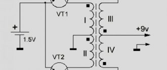
Manufacturing a high-voltage module from an energy-saving lamp
And such a device can be easily made with your own hands. But where can I get a high-voltage module? You can use a regular incandescent light bulb. At first we wind no more than 80 skeins. The second layer is 400-600 turns. Between each layer, do not forget to insulate with tape.
To test the device, we connect it through a 35 W limit light bulb. The result is a fairly powerful high-voltage ignition module.
Replacement of high voltage transformers
The most common cause of high-voltage power supply failure in a laser tube is the burnout of high-voltage transformers. The power supply of a laser tube usually has two transformers, and if one of them fails, the laser tube loses power, and if both transformers fail, the laser tube does not light up. High-voltage transformers for tube power supplies can be re-soldered. In the assortment of the SINE SERVICE company they are available:
- High voltage transformer for power supply 100, 150 W
- High voltage transformer for power supply 40 W
- High voltage transformer for power supply 60 W
- High voltage transformer for power supply 80 W
- High voltage transformer for power supply unit Reci DY10
- High voltage transformer for power supply unit Reci DY13
- High voltage transformer for power supply unit Reci DY20
- High voltage transformer for Yueming 100 W power supply
- High voltage transformer for Yueming 80 W power supply
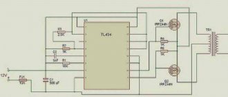
Testing the converter in action
The inverter can withstand 10 minutes of continuous operation, after which the transformers begin to require cooling. The transistors do not heat up too much - the heatsinks remain almost cold. Most of the heat is generated on the bridge rectifier, which can get quite hot - it also has a large heatsink.
The inverter is capable of delivering large discharges due to its significant current efficiency. The maximum length of an extended zipper is just over 20 cm.
We will also show oscillogram signals: The first is a sinusoid on an LC circuit without a lit arc. The last screenshot shows a sequence of pulses on one of the field keys.
AliExpress - Products from China at wholesale prices - Opt-aliexpress.ru
5pcs/lot IERNA Power Steering Switch Sensor for Peugeot 206 307 306 406 Citroen C4 Partenaire 1
Sale
CAN Bus Adapter Gateway Simulator VW Jetta Passat B5 Golf MK4 Polo 9N RCN210 Conversion Cable
Sale
Parktronic 1EW63CDMAA PDC Remote control sensor 1EW63KARAA parking 4ps radar
Sale
Digital Pressure -Sensor DP-102 Detection Range-0.1-1 MPA | Home improvement
Sale
Sandblaster High Pressure Washer Karcher K2 K3 K4 K5 K6 K7 | Cars
Sale
LED Car Door Light Logo Peugeot 206 207 806 807 208 3008 RCZ 307 508 408
Sale
10 pieces. car emblem 14 mm 16 | Cars and motorcycles
Sale
Multi-function steering wheel control button for RCN210 CAN decoder
Sale
Transparent Soft Cases Covers ET The Extra-Terrestrial For iPod Touch iPhone 4 4S 5 5S 5C SE 6 6S 7 8 X XR XS Plus MAX |
Sale
Stickers for car keys with emblem emblem 5 pcs. 16mm accessories for Peugeot
Sale
New Map Sensor 9639418880 for CITROEN Xsara Picasso 1 6 2 0 PEUGEOT 206 4 0261230057 0261230034 19201K 1920AN 9631813680 |
Sale
Case 360 Degree Silicone Clear Cover for Huawei HONOR 7C PRO 7CPRO LND-AL29 LND-AL30 LND-AL40 Hard PC Back Soft TPU Front |
Sale
Waterproof O-ring for scuba diving MK
Sale
Glass Jar for Ventotherapy Home Single Vacuum Care Cup
Sale
3D Squishy Cat Cases For Huawei P smart P8 p9 lite mini 2017 Liquid Glitter Cover Honor 8 pro 9 10 V10 6A 6X 5A 5X 5C 4A |
Sale
90*90*90mm/3.54in right-angle reflection laser experimental optical prism without aluminum coating | Tools
Sale
Metal candlesticks black/gold candle stand round iron
Sale
Vintage Knitted Cardigan with Diamonds Women's Long Sleeve Winter
Sale
Urijk Wardrobe Storage Bags Transparent Dress Clothes Coat Garment Suit Cover Case Dustproof Covers Home Zipper | A house and a garden
Sale
EX16 Smart Watch Men Sports Watch Notification Remote Control
Sale
Glitter Crystal Texture Cases for iPhone 7 8 Plus Smooth TPU Women Cases
Sale
Gold Custom Photo Iced Out Wings Medallions Necklace and Pendant
Sale
Handmade pink mini dress 1 piece | Toys and hobbies
Sale
Baby Summer Rompers for Newborn Children Little Girls Cute
Sale
Winding instructions
The core must be wrapped with tape (5 layers), a wire with the calculated diameter must be inserted into the groove, and the number of turns calculated for the primary winding must be wound along the entire length. Both ends of the winding are brought out to one side and insulated with vinyl.
The last turn must be secured (simple threads will do) to prevent unwinding.
Next, 4-5 layers of tape are wound, the structure is placed in the body of a disposable syringe 3 cm long. 2 rows of tape and the number of turns calculated for the secondary are wound on the syringe, the width of the winding is approximately 1.5 cm. Each layer must be insulated with tape or two layers of fluoroplastic tape. The ends of the second winding are brought out on both sides. As a result, three outputs are obtained from one end, and one from the other.
The finished structure is insulated with tape (5 layers), flexible wires (leads) are soldered, and another 5 layers of tape are wound.
If the wire breaks during the winding process, the ends must be stripped, twisted, soldered and insulated. The electrical strength is increased by impregnation of each layer of winding with varnish based on acrylic or epoxy resin.
In order to make a transformer with your own hands, it is not necessary to buy a new wire. The old one is also suitable if the segments are connected correctly (twisted and soldered). When winding, the turns should be pressed tightly against each other. It is not advisable to lay them perpendicular to the core (a slight tilt is required). Kinks and folds are not allowed, so a certain amount of tension is required. The insulation tape should be cut into 1.5 cm wide strips to make it easier to cover the wire.