It is common for a car to break down; simple breakdowns related to electrical equipment can be repaired by a car owner who is familiar with electrical engineering on his own. But for this you need a device with which you can measure voltage in various parts of the electrical circuit, resistance, and make continuity tests.
That is why many car enthusiasts, among other tools, carry a multimeter with them. However, if the machine does not break down often, the multimeter may lie idle for a long time, and as soon as it is needed, it may turn out that its battery does not work.
In this case, it is advisable to power the multimeter from the car's on-board network, for example, through a 78L09 stabilizer. But, alas, the design of the multimeter is such that it cannot be powered from the circuit in which it will take measurements. You need a power source that is not galvanically connected to the car battery.
Nowadays, almost every car is equipped (at the factory or by the owner) with a device for charging and powering a cell phone and other portable devices that are powered or charged via a USB port. This device is a pulse or linear voltage regulator for 5V output to a standard USB socket. In addition, there are many inexpensive charging and power units on sale with an output voltage of 5V and a USB connector; almost all portable equipment is now equipped with such units.
So, in order to make the power supply of the multimeter universal (in a car, from a PC USB port, from a power supply and charging unit with a USB connector), it was decided to make a galvanically isolated voltage converter powered by a voltage of 5V (via a USB cable) both in shape and the same size as a 9-volt Krona battery.
The multimeter is powered by a 1.5 volt battery
Digital multimeters are very popular among radio amateurs and professionals due to their versatility. To power them, as a rule, a nine-volt Krona battery is used, which has noticeable self-discharge, low capacity and a higher price compared to other elements. The proposed power supply device for a digital multimeter from one AA element with a voltage of 1.5 volts will avoid these operational drawbacks and simplify the operation of the device.
There are many different circuits offered on the Internet for converting 1.5 to 9 volts. Each has its pros and cons. This device is made on the basis of A. Chaplygin’s circuit, published in the magazine “Radio” (11.2001, p. 42)
. The difference between this version of the converter is the location of the battery and voltage converter in the cover of the multimeter case, instead of creating a compact power supply installed instead of the Krona battery. This allows you to replace the AA element at any time, without disassembling the device, and, if necessary, turn off the converter (Jack 3.5 connector) with automatic activation of the Krona backup battery located in its compartment. In addition, when manufacturing a voltage converter, there is no need to miniaturize the product. It’s faster and easier to wind the transformer on a ring with a larger diameter, better heat dissipation, and a freer circuit board. This arrangement of components in the cover of the case does not interfere with working with the multimeter. This converter can be made in any suitable housing and used in a wide variety of devices that require power from a nine-volt Krona battery. These are multimeters, watches, electronic scales and toys, medical devices.
Voltage converter generator circuit
A DC boost inverter is proposed that has good output data with a minimum of input elements. The diagram is shown in the figure.
A push-pull pulse generator is assembled using transistors VT1 and VT2. The positive feedback current flows through the secondary windings of transformer T1 and the load connected between the + 9 V circuit and the common wire. Due to proportional current control of transistors, switching losses are significantly reduced and the efficiency of the converter is increased to 80... 85%. Instead of a high-frequency voltage rectifier, base-emitter junctions of the transistors of the generator itself are used. In this case, the value of the base current becomes proportional to the value of the load current, which makes the converter very economical. Another feature of the circuit is the interruption of oscillations when there is no load, which can automatically solve the power management problem. Almost no current is consumed from the battery when there is no load. The converter will turn on itself when it is required to power something and turn off when the load is disconnected. But since most modern multimeters have an automatic power-off function, to avoid modification of the multimeter circuit, it is easier to install a power switch for the converter.
Manufacturing of voltage converter transformer
The basis of the pulse generator is transformer T1. The magnetic core of transformer T1 is a K20x6x4 or K10x6x4.5 ring made of 2000NM ferrite. You can take a ring from an old motherboard.
The order of winding the transformer.
1. First you need to prepare the ferrite ring. • To prevent the wire from cutting through the insulating gasket and damaging its insulation, it is advisable to dull the sharp edges of the ferrite ring with fine-grained sandpaper or a needle file. • Wrap the insulating pad around the ring core to prevent damage to the wire insulation. To insulate the ring, you can use varnished cloth, electrical tape, transformer paper, tracing paper, lavsan or fluoroplastic tape.
2. Winding of transformer windings with a transformation ratio of 1/7: primary winding - 2x4 turns, secondary winding - 2x28 turns of insulated wire PEV -0.25. Each pair of windings is wound simultaneously into two wires. Fold the wire of the measured length in half and with the folded wire begin to tightly wind the required number of turns onto the ring.
To avoid damage to the wire insulation during operation, if possible, use MGTF wire or other insulated wire with a diameter of 0.2-0.35 mm. This will slightly increase the dimensions of the transformer and will lead to the formation of a second winding layer, but will guarantee uninterrupted operation of the voltage converter. • First, the secondary windings lll and lV (2x28 turns) of the transistor base circuit are wound (see converter diagram). • Then, in the free space of the ring, also in two wires, the primary windings l and ll (2x4 turns) of the transistor collector circuit are wound. • As a result, after cutting the loop of the beginning of the winding, each of the windings will have 4 wires - two on each side of the winding. We take the wire from the end of one half of the winding (l) and the wire from the beginning of the second half of the winding (ll) and connect them together. We proceed similarly with the second winding (lll and lV). It should look something like this: (red terminal is the middle of the lower winding (+), black terminal is the middle of the upper winding (common wire)).
• When winding the windings, the turns can be secured with glue “BF”, “88” or colored electrical tape indicating the beginning and end of the winding in different colors, which will later help to correctly assemble the transformer windings. • When winding all the coils, you must strictly follow one winding direction, and also mark the beginning and end of the windings. The beginning of each winding is marked on the diagram with a dot at the terminal. If the phasing of the windings is not observed, the generator will not start, since in this case the conditions necessary for generation will be violated. For the same purpose, as an option, it is possible to use two different-colored wires from the network cable.
Voltage converter assembly
For operation in low-power converters, as in our case, transistors A562, KT208, KT209, KT501, MP20, MP21 are suitable. You may have to select the number of turns of the secondary winding of the transformer. This is due to different voltage drops across pn junctions for different types of transistors. Transistors should be selected based on the permissible values of the base current (it should not be less than the load current) and the emitter-base reverse voltage. That is, the maximum permissible base-emitter voltage must exceed the required output voltage of the converter. In order to reduce noise and stabilize the output voltage, the converter is supplemented with a unit of two electrolytic capacitors (to smooth out voltage ripples) and an integrated stabilizer 7809 (with a stabilization voltage of 9 volts) according to the scheme:
We assemble the converter according to the diagram and solder all the incoming elements on a textolite board cut from a universal circuit board sold in radio products using the surface-mounting method. The dimensions of the board are selected depending on the sizes of the selected transistors, the resulting transformer and the installation location of the converter. The input, output and common bus of the converter are led out by a flexible stranded wire. The output wires, with a voltage of +9V, end with a 3.5 Jack connector for connecting to a multimeter. The input wires are connected to a cassette with a 1.5 volt battery installed.
The AA battery (1.5V) is installed in a double cassette from a portable receiver.
One place is occupied by the battery, the other place is used to install the power switch and secure the entire cassette, through an adapter textolite strip, in the multimeter case.
Setting up the converter.
We check that the converter is assembled correctly, connect the battery and use the device to check the presence and magnitude of voltage at the converter output (+9V). If generation does not occur and there is no voltage at the output, check that all coils are connected correctly. The dots on the converter diagram mark the beginning of each winding. Try swapping the ends of one of the windings (input or output). The converter is capable of operating when the input voltage is reduced to 0.8 - 1.0 volts and receives a voltage of 9 volts from one galvanic element with a voltage of 1.5 V.
Refinement of the multimeter
To connect the converter to the multimeter, you need to find a free space inside the device and install a socket there for a 3.5 Jack plug or a similar available connector. In my M890D multimeter, there was free space in the corner, to the left of the Krona battery compartment. An electric razor case is used as a case for the multimeter.
Prepared by: Smirnov I.K.
sdelaysam-svoimirukami.ru
Replacing multimeter wires and probes
First of all, what 99% of users of cheap Chinese multimeters encounter is the failure of low-quality measurement probes.
Firstly, the tips of the probes may break. When touching an oxidized or slightly rusty surface for measurement, the surface must be lightly cleaned to ensure reliable contact. The most convenient way to do this is, of course, using the probe itself. But as soon as you start scraping, at that moment the tip may break off.
Secondly, the cross-section of the wires included in the kit also does not stand up to criticism. Not only are they flimsy, but this will also affect the error of the multimeter. Especially when the resistance of the probes themselves plays a significant role during measurements.
Most often, a wire break occurs at the connection points at the plug-in contact and directly at the soldering of the sharp tip of the probe.
When this happens, you will be surprised how thin the wiring inside is really.
Meanwhile, the multimeter must be designed to measure current loads up to 10A! It is not clear how this can be done using such a wire.
Here are real data on current consumption measurements for flashlights, made using standard probes included in the kit and using homemade probes with a cross section of 1.5 mm2. As you can see, the difference in error is more than significant.
The plug-in contacts in the multimeter connectors also become loose over time and worsen the overall resistance of the circuit during measurements.
In general, the unequivocal verdict of all owners of DT830 multimeters and other models is that the probes need to be modified or changed immediately after purchasing the tool.
If you are the happy owner of a lathe or you know a lathe, you can make the probe handles yourself from some insulating material, such as pieces of unnecessary plastic.
The tips of the probes are made from a sharpened drill. The drill itself is a hardened metal and can be used to easily scrape off any carbon deposits or rust without the risk of damaging the probe.
When replacing plug-in contacts, it is best to use the following plugs used in audio equipment for speaker sockets.
If you really are on a collective farm or there are no other options at hand, then as a last resort you can use ordinary contacts from a collapsible plug. They also fit perfectly into the connector on the multimeter.
At the same time, do not forget to insulate the ends that will stick out outside the multimeter, in the places where the wires are soldered to the plug, with a heat pipe.
When it is not possible to make probes yourself, the body can be left the same, replacing only the wires.
In this case, three options are possible:
- order silicone wires cheaply in China
- use flexible wires from old electric shavers
- buy an audio cable with a cross section of 1.5 mm2 from a radio store
After replacement, such wires will very easily be collected into a bundle without getting tangled.
Secondly, they are designed to withstand a huge number of bends and will break no sooner than the multimeter itself fails.
Thirdly, the measurement error due to their larger cross-section compared to the original ones will be minimal. That is, there are continuous advantages everywhere.
Important note: when replacing wires, you should not try to make them much longer than those that came with the kit. Remember that the length of the wire, as well as its cross-section, affects the overall resistance of the circuit.
If you make long wires up to 1.5 m, taking into account all the connections, the resistance on them can reach several ohms!
Those who do not want to do homemade work can order ready-made high-quality silicone probes with many tips from Ali here.
To ensure that new probes with wire take up minimal space, you can twist them into a spiral. To do this, a new wire is wound around the tube, wrapped in electrical tape to secure it, and the whole thing is heated with a hair dryer for a couple of minutes. As a result, you get this result.
In a cheap version, this trick will not work. And if you use a hair dryer to heat it up, the insulation may even float.
VOLTAGE CONVERTER 1.5 - 9 VOLTS
To power a digital multimeter from 1 AA battery, instead of a 9 V “crown,” I recently assembled this converter. Although you can power anything from it, not necessarily testers. Unlike specialized DC-DC inverters, there are only a couple of transistors and a coil. Mounting is mounted directly on the battery connector. If something happens, you can easily disconnect and return the “crown”.
9V Converter Circuit
The most energy-intensive mode in a multimeter is dialing. If the supply voltage drops significantly when the probes are shorted, then you need to increase the diameter of wire L2 (stopped at 0.3 mm PEV-2). The diameter of the L1 wire is not critical, I used 0.18 mm and only for reasons of “survivability”, since thinner ones can be accidentally torn off. As a result, I assembled this circuit with a ring D=12 d=7 h=5 mm on VT1 2SC3420 - it pumps 100 V without load, it turned out to be the best (R1 = 130 Ohm). Also successfully tested were KT315A (a bit weak, R1 = 1 kOhm), KT863 (pumps well).
Debugging the circuit
Disconnect ZD1, instead of R1 we set a tuning resistance of 4.7 kOhm; as a load - R = 1 kOhm. We achieve maximum voltage at the load by changing resistance R1. Without a load, this circuit easily produces 100 volts or more, so when debugging, set C2 to a voltage of at least 200V and do not forget to discharge it.
Important addition. There is no need to use a ring here! We take a ready-made inductor for 330 mH and higher, wind 20-25 turns of L1 over its winding with any wire, and fix it with heat shrink. AND THAT'S ALL! It pumps even better than the ring.
Tested by me with VT1 2SC3420 and IRL3705 (R1 = 130 Ohm, VD1 - HER108). The field-effect transistor IRL3705 works great, but it needs a supply voltage of at least 1 V and between the gate and ground there is a resistor of several kilo-ohms and a zener diode of 6-10 V. If it does not work, then we swap the ends of one of the windings. During experiments, the converter actually worked starting even from 0.8 V!
Then I made another copy - also successful. As for the efficiency of the circuit, let's calculate: the measured current consumption is 53 mA, the input voltage is 0.763V and the output is 6.2V and Rout = 980 Ohm.
At the input Pin=Iin*Uin=0.053A*0.763V=0.04043W
Output Pout=Uout*Uout/Rout =6.2V*6.2V/980=0.039224W (Watt).
Efficiency = Pout/Pin= 0.969 or 96.9% - an excellent result!
Even if it’s 90%, that’s not weak either. Frankly speaking, this circuit with a ring has been known for a long time, I just added feedback on Uout on a field-effect transistor and figured out how to wind it up and use a ready-made inductor, because it’s inconvenient to wind on rings, and it’s too lazy, even if it’s 20 turns. And the dimensions of the ring are larger. Author of the article - Evgeny :)
IP Forum
Discuss the article VOLTAGE CONVERTER 1.5 - 9 VOLTS
radioskot.ru
Simple voltage converter 1.5 - 9 volts
Author: Beshenyi City: Zhitomir, Ukraine
Amateur radio design diagram of a very simple DC voltage converter of 1.5 volts to 9 volts.
The “crown” in the multimeter has once again discharged. I was tired of buying so I decided to assemble a voltage converter in order to power the device from one AA battery. I found the diagram on the Internet (Fig. 1), the parts I used were those that came to hand:
Modified scheme.
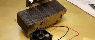
I took a transformer from a burnt-out mobile phone charger, removed the existing windings and wound new ones. The wire was found with a diameter of 0.5 mm. Winding 1 contains 2 turns, winding 2 contains 5 turns, winding 3 contains 20 turns. Resistors R1 and R2 are 100 ohms each, C1 is from 10 to 100 μF. C1 and diode VD1 All from the same charging faults. Transistor VT1 is also not critical: KT814-819, KT805 and even KT315 (tried it). Naturally, if the transistor has reverse conductivity, then you need to change the polarity of the supply voltage to the reverse. I found a powerful KT837 (for greater reliability). The wound transformer and all the necessary parts can be seen in Figure 2:
I made the board using a cutter, that is, without etching (Fig. 3), fortunately there is plenty of space in the multimeter, so I didn’t bother too much with the size:
I assembled it (Fig. 4), applied power and everything worked. If it does not start, you need to swap the terminals of winding 1 of the transformer:
I mounted everything into the multimeter housing (Fig. 5), installed the power button and that’s it:
And I wish you success in repeating the design. With uv. Beshenyi.
radio-stv.ru
Project.
As a housing for a homemade voltage converter, I decided to use a housing from a used Krona battery. This design, in my opinion, is more universal, and anyway, nothing larger than the “Crown” will fit into the DT-830B multimeter.
A drawing of the proposed design showed that a AAA AA battery can be placed in a battery case with a minimal increase in the size of the latter.
Namely. The length of the body can be increased by straightening one of the flared edges of the tin shell.
At the same time, the rear wall had to be tilted slightly so that the nut securing the socket did not increase the dimensions of the case.
9 VOLTS VOLTAGE CONVERTER
The first article is dated May 2016, when this voltage converter was assembled. The implementation of this project was a forced matter, I was tired of disassembling the case of the multimeter to charge the battery, and the battery was pretty worn out, I should have thought about replacing it or something else. I chose “other”, and this is a new thing - undeveloped, so I soldered a simple voltage conversion circuit on a piece of ordinary cardboard and inserted it into the power compartment of the multimeter. absolutely without any illusions or excessive expectations. You can see the details here - “simple voltage converter”
In addition, there was an additional nuance that was not in favor of the circuit; instead of a 1.5 V battery, it was powered by a 1.2 V battery, and even in AAA format. Even visually it is clear that the weakest option. I made this choice for two reasons: first, such batteries were available and were gathering dust without use, the second and main thing was that a suitable place for installation was found specifically for this type of battery.
Scheme
Over the past, almost a year, there has been enough time to evaluate the converter both as a device in general, and a specific assembled circuit in particular, and an addition introduced to the multimeter power switch design (installation of an additional power switch button from the battery to the converter in parallel with the standard one, for working with her in tandem). I’ll be brief - as a user, I’m happy with absolutely everything, with one small caveat. The fact is that to turn on the multimeter, the standard button had to be pressed twice - to fix it, it was necessary to open the multimeter case and adjust the push rod of the additional button. But over the previous years of using the multimeter, I got so tired of tinkering with its insides that I agreed to quickly double-click the standard button during all this time, because everything else was so organic that there are no words. The battery lasted at least a week, if necessary, replacement was carried out within 15 seconds, if not in a hurry. However, I always remembered that the matter needed to be completed, and now, finally, I was worthy. I took out a temporary scarf and, looking at it, without changing the existing circuit, drew a printed circuit board in Layout.
I printed it out, transferred the drawing onto foil PCB, etched and transferred all the electronic components to the resulting printed circuit board. During manufacturing, the dimensions of the printed circuit board were taken not for the power compartment, but for the housing made of a Krona battery. The space is somewhat smaller, but the design is so comfortable and complete. See how to make such a housing here (“Electronic device housing from a battery”).
In accordance with the intentions, the terminal block from Krona and the manufactured plug, instead of the standard bottom, were soldered to the board, using additional metal elements for this. The fastening turned out to be quite reliable, and everything together took on the appearance of a finished structure.
I performed a test run and measured the output voltage. Since the multimeter was disassembled, I did it using TL-4m. The needle showed almost 10 volts. I didn’t believe it, the electronic components are the same, only the board is different. By the way, there was a photo of measuring the output voltage from the time of assembling the temporary board, then it was equal to 8.7 V. I had to assemble a multimeter powered from the crown. Indeed, the output voltage increased by 0.8 V. Yes, the correct printed circuit board is not a temporary one.
I agreed with powering my multimeter with a voltage of 9.5 volts and placed the assembled circuit in a shell, but before that I placed an insulating pad made of thick polyethylene on the printed conductors. The outer shell is made of very thin sheet metal, so there is no reliability on it; in order to avoid a short circuit, let there be a gasket. The converter is completely ready for use.
Before assembling the multimeter, I made a test switch on and very usefully, the power button again required a double press and reminded me of the necessary adjustment. And so the device functioned normally.
Installation
The adjustment consisted in the fact that it was necessary to remove the main button and the “boom” located on it with the screw rod located inside for pressing the power supply key to the converter from the 1.2 V battery, and turn the screw half a turn counterclockwise, that is, unscrew – increase the length of the rod. Now the converter turned on a moment earlier and, accordingly, the multimeter turned on as normal (from the first press).
And to confirm my IMHO that replacing the battery located on the outside of the body of a measuring device is much more attractive than charging it when located inside, I invite you to watch a short video demonstrating this process. Please note that the replacement itself lasts 15 seconds (in working order it is 5).
Video
Especially for Elvo.ru Author - Babay iz Barnaula.
Power supply circuits
elwo.ru
Prologue.
I have two multimeters, and both have the same drawback - they are powered by a 9-volt Krona battery.
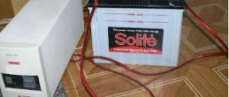
I always tried to have a fresh 9-volt battery in stock, but for some reason, when it was necessary to measure something with an accuracy higher than that of a pointer instrument, the Krona turned out to be either inoperative or only lasted for a few hours of operation.
The last time, I had to alternately recharge two crowns from the power supply in order to make the necessary measurements, although 12.2012 was written on the crowns. In general, patience came to an end, and I got to work.
Mini converter from 1.5 V to 220 V
If you have a broken cell phone charger lying around idle, then you can use it to make one small but necessary homemade product. This is a simple voltage converter from constant 1.5 Volts to variable 220 Volts. The diagram is truly elementary and contains only 3 parts.
Manufacturing a mini voltage converter
We disassemble the charger housing and remove the board from there.
We solder the transformer from this board.
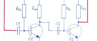
Converter circuit
As already mentioned, the scheme is the simplest. Before assembling it, you need to “ring” the transformer with a tester and find out the resistance of each winding. There should be three of them in total. Naturally, the resistance of the windings of your transformer may differ slightly - this is not a big deal. But if the discrepancies are dramatic, then such an instance may not be suitable. We assemble the converter according to the diagram.
The circuit uses a “2SD882” transistor; it can be replaced by any low-frequency “pnp” medium-power structure. Or the domestic analogue KT815, KT817. Everything is assembled by hanging installation without a fee in 5 minutes. Solder the wires from the light bulb socket and from the battery.
The device works immediately when turned on and does not require configuration. If generation does not start when you first turn it on, swap the contacts of one of the low-voltage windings. A 220 V LED lamp with a power of 3 W was used as a load.
The operating frequency of the converter is about 25 kHz. If you power the circuit with 3 Volts, the brightness of the lamp will increase and it will definitely shine at full power. You can connect another charger as a load and charge your mobile phone from the batteries.
Watch the video
sdelaysam-svoimirukami.ru