An electric shock device (taser), abbreviated as ESD, is a publicly available special means of protection against offenders and an effective means of repelling and protecting against attacks by animals, such as dogs.
There is a wide range of shockers on the market, but the operating principle of all models is the same. They differ from each other only in the voltage on the electrodes, arc power, reliability and the presence of additional services, such as a flashlight and built-in charger and others.
The main consumer parameters of any shocker are the no-load voltage on the spark gap electrodes and the arc power. According to GOST R 50940-96 “Electroshock devices. General technical conditions." According to the voltage on the electrodes, shockers are divided into five groups. The first - from 70 to 90 kV, the second from 45 to 70 kV, the third from 20 to 45 kV, the fourth from 12 to 20 kV and the fifth up to 12 kV inclusive. And according to the power of the arc, there are three types. The first - from 2 to 3 W, the second - from 1 to 2 W and the third, from 0.3 to 1 W.
Classification of stun guns
Depending on the combination of type and group that a particular stun gun model has, it can be classified into one of five classes according to GOST R 50940-96. It is easy to find out which class the stun gun belongs to from the table below. For example, a stun gun of the second type of the third group belongs to the third class.
| Classification of electroshock devices according to impact effectiveness according to GOST R 50940-96 | |||||
| Arc power type, W | Voltage group at working electrodes, kV | ||||
| First 70–90 | Second 45-70 | Third 20-45 | Fourth 12-20 | Fifth to 12 | |
| First – from 2 to 3 | 1 | 2 | 3 | 4 | 5 |
| Second – from 1 to 2 | 2 | 2 | 3 | 4 | 5 |
| Third – from 0.3 to 1 | 3 | 3 | 3 | 4 | 5 |
First class stun guns are very powerful and expensive; these are weapons for special forces. For personal protection, a second or third class shocker is quite suitable. Stun guns of the fourth and fifth classes are more suitable for intimidating an attacker than for real protection.
Attention, if you decide to buy a stun gun, then consider the following. To temporarily paralyze the physical strength of the attacker, the time of continuous exposure of the shocker discharge to his body should be about 3 seconds. With a shorter exposure time, you will only anger the offender and then it is quite possible that you yourself will fall under the influence of your own shocker. It is permissible to use a shocker only if you are confident that you can hold the shocker pressed by the electrodes to the enemy’s body for three seconds.
Some intermediate conclusions and reflections.
First of all, it seems to me that you should not chase a large penetration distance. Firstly, such an impulse will not be effective because As the distance increases, the pulse parameters drop, at least the amplitude for sure. Secondly, to obtain a long breakdown pulse, a higher voltage is required, which is obtained due to a larger number of turns in the secondary winding, and this in turn results in a decrease in the pulse current and an increase in winding resistance.
Those. the point of using a contact shocker through a layer of clothing two centimeters thick under each spark gap seems extremely doubtful; something will certainly reach the body, but it probably won’t have the desired effect. It seems to me optimal to have a confident breakdown of 3-3.5 cm, perhaps less.
This is followed by confusion with the core used; their various types and sizes have shown a rather insignificant effect on the duration of the combat impulse, with a difference literally in the region of 5-10%.
The diameter of the secondary winding wire is important, and judging by experiments, it affects the amplitude of the output pulse, but it is not clear what is more important here, the active resistance of the wire or the inductive one.
The diameter of the primary winding wire in all experiments was 0.6 insulation, I don’t have another suitable one, 0.85 seems excessive to me and I did not test it.
The influence of the number of turns in the primary winding on the initial discharge rate of the combat capacitor is noticeable; with a decrease in the number of turns, the discharge speed increases, which is noticeable by the sharper angle at the beginning of the oscillogram. At 18 turns, there is a noticeable drop in the pulse amplitude; accordingly, we can make the assumption that it is optimal to use 20-22 turns with the described types of core.
The increase in the discharge rate is also noticeable on cores of smaller volume; accordingly, we can make the assumption that on thin cores, to maintain a smoother discharge, more turns are needed, although the question remains - is this smooth discharge necessary?
During the experiments, no measurements were made of the igniting (discharge-producing) pulse because Unfortunately, I don’t know how to measure the ~80kV impulse. In the ignition pulse, according to my guesses, the current is important, with an increase in which a more reliable breakdown of materials between the spark gaps will occur. In order to obtain current, you need to reduce the number of turns of the secondary winding, which in turn will reduce the distance of reliable breakdown. Vicious circle.
Among other things, it seems that the duration of the pulse, in addition to the capacitance of the igniting capacitor, is also affected by the capacitance of the combat capacitor, because discharging into the ionized channel, it thereby supports it. And if we take into account that the primary converter operates continuously, then its power also affects it, because During operation of the ionized channel, the combat capacitor is constantly recharged. Accordingly, according to my assumption, if during the breakdown of the spark gap it was possible to disconnect the igniting capacitor from the converter and its power was used only for the combat one, the lifetime of the ionized channel could increase.
This can also be checked by changing the combat capacity twice, to compare the results, I’ll try it when they arrive.
Another important point: you cannot use standard EPCOS at 1400 volts as a safety arrester (on the electrode), because with it, when the electrodes contact directly the body (in my case, the divider), an arc occurs. Accordingly, if you want to poke a naked body, and simply to protect the circuit, the arrester should be made of two electrodes with a distance of three millimeters.
Electrical circuit of a stun gun, principle of operation
I had to repair a JSJ-704 type stun gun with a flashlight. The appearance of this shocker is shown in the photo above. According to external signs, the shocker was in good working order, the LED indicating the battery charge was lit when the shocker was connected to the network. The flashlight worked, the discharge readiness LED also glowed, but when I pressed the discharge button, nothing happened. It became obvious that the fault lies in the high-voltage converter circuit.
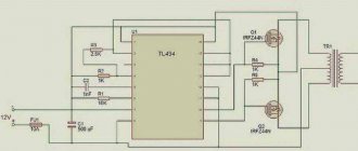
All stun guns, regardless of model and manufacturer, work on the same principle. The voltage from the battery or batteries is supplied to a high-frequency generator, which converts DC voltage into AC voltage. Alternating voltage is supplied to a step-up high-voltage transformer, the secondary winding of which is connected directly or through a voltage multiplier to the external electrodes of the shocker. When the stun gun is turned on, a powerful electric arc occurs between the electrodes.
The photograph shows the electrical circuit diagram of the stun gun model JSJ-704.
The circuit consists of several functional units. The battery charger GB1 is assembled on capacitor C1 and diode bridge VD1. C1 limits the charge current to 80 mA, the diode bridge rectifies the voltage. Resistor R1 serves to discharge capacitor C1 through it after disconnecting the shocker from the mains voltage to prevent discharge of the capacitor through the human body in case of accidental contact with the plug terminals.
LED HL1 serves to indicate the connection of the shocker to a 220 V electrical network, R2 serves to limit the current flow through HL1. This part of the circuit is not directly involved in the operation of the shocker and serves only to charge the battery and may not be present in models of other shockers. Charging time for a completely discharged battery is 15 hours.
LED HL2 with current-limiting resistor R3 is a flashlight. The flashlight turns on when the S1 switch slider is moved to the middle position. The flashlight is placed between the shocker discharger and is convenient in the dark. Some models may not have shockers.
The HL3 LED with current-limiting resistor R4 serves to indicate that the shocker is in ready-to-use mode. To prevent accidental activation of the discharge mode, triple protection is provided in the form of three switches. In order for a discharge to appear between the electrodes, you must first move the slide switch S1 (located next to the round button) to the extreme right position, then the second slide switch S2 (located next to the connector for connecting the shocker to the charging network) to the right position, after which the HL3 LED will light up, informing that the shocker is ready to be discharged. And only after this, when you press the round pusher of the return button S3 “Start”, a discharge in the form of a blue arc will appear between the electrodes.
How to make a transformer correctly
To assemble the converter, you need to properly make its main component - the step-up transformer. To do this, take, for example, a core from a switching power supply. Having carefully freed it from the old winding, carefully wind the new one. The primary winding is made with a wire with a diameter of 0.5-0.8 mm, applying 12 turns and moving away from the middle (wind 6 turns, twist the wire, make another 6 turns in the same direction). Then you need to insulate it with transparent tape, making 5 layers of it. A secondary winding is placed on top, making 600 turns with a wire with a diameter of 0.08-0.1 mm, applying two layers of adhesive tape for insulation every 50 turns. This will protect the transformer from breakdowns. Both windings are made strictly in the same direction. For better insulation, you can fill the entire structure with epoxy resin. A wire with stranded insulated wires must be soldered to the terminals from the secondary winding. It is recommended to place the resulting transistor on an aluminum heat sink.
How to disassemble a stun gun
Due to the fact that the halves of the shocker body were fastened together using four self-tapping screws, disassembling it was not difficult.
The heads of three screws were clearly visible in the secret holes, and the fourth was covered with a label. After unscrewing all the screws, the halves came apart easily.
After removing the cover, the following picture was revealed. As you can see in the photo, the installation of the stun gun parts is carried out using a hinged method; there is no printed circuit board. The high-voltage converter is filled with compound. This is good, since it is protected from moisture and therefore more reliable, but the bad thing is that the converter is not repairable. It should be noted that although the shocker is made in China, all soldering is done with high quality and reliability.
Do-it-yourself spy pen stun gun
On our website, from time to time we review videos on making homemade products, which as such cannot be used for a specific purpose. Such homemade products are made solely for fun. It is this kind of homemade product that will be discussed in this material, during which we will review a video on making a spy stun gun handle.
As always, first of all, we suggest that you familiarize yourself with the author’s video, after which we will move on to the actual process of making a homemade spy pen.
[media=https://www.youtube.com/watch?v=rh5WzIYBOQk&list=UUyUppWKbVCNBuv7zo8V7zWA]
What do we need: - one small carnation; - two lighters; - handle with button; - a small hacksaw for metal; - glue gun.
Let us immediately note that in the design of the spy pen we will use one lighter, and the second will be used to heat the nail. As for the handle, it should be slightly thick so that the piezo element can fit into it. It is also important that the clip on the handle was metal so that the spark could pass through it.
First of all, we must remove the piezoelectric element from the lighter. The author's lighter has a slightly different design than usual, so he uses a small screwdriver with which he unscrews the bolt on the bottom of the lighter, pulls out the core and removes the piezo element.
Now you can move on to the handle. First you need to disassemble it. If your pen has plastic sleeves, like the author's pen, then they must be removed.
We apply a piezoelectric element to the upper plastic sleeve and place two marks: one mark where the piezoelectric element button ends, and the second where the metal part ends.
Next, take a small hacksaw and cut according to the marks you made.
We no longer need the middle part of the bushing.
We remove the metal clip, heat the nail with a lighter and make a small hole at the clip’s fastening.
We cut the clip mount for the piezoelectric element wire with a hacksaw.
You can proceed to the assembly. First of all, insert the button along with the upper part of the plastic sleeve.
Next, using a glue gun, carefully glue the insulation of the piezoelectric element wire so that the spark does not strike to the side.
We glue the piezoelectric element to the second part of the sleeve.
Slightly bend the upper part of the piezoelectric element wire and install it into the handle, carefully threading the wire through the hole.
Now we insert the wire into the groove that we made earlier.
We clamp it with a metal clip. The stun gun handle is ready.
Delivery of new homemade products to the post office
Receive a selection of new homemade products by email. No spam, only useful ideas!
*By filling out the form you agree to the processing of personal data
Become the author of the site, publish your own articles, descriptions of homemade products and pay for the text. Read more here.
Stun gun repair
Attention, when repairing a stun gun, care must be taken not to accidentally touch the discharge electrodes while the stun gun is operating.
Otherwise, you may get unpleasant sensations.
Repairing any electronic device begins with checking the power supply. Therefore, the first thing you need to do is check the performance of the battery or batteries. The test can be done using a multimeter. If the shocker is powered by batteries, then in addition to their serviceability, you need to check the condition of the contacts in the battery compartment. It happens that they oxidize or their springy properties weaken.
When the “Start” button was pressed while the “Ready” indicator was on, no discharge occurred, but the voltage at the battery terminals, equal to 7.2 V, did not drop. Therefore, it's not the battery. I checked the voltage when pressing the “Start” button on the input terminals of the High Voltage Converter, it dropped to several volts. This voltage was enough to light up the HL3 LED, but not enough to operate the converter.
Therefore, the fault was in poor contact of one of the switches, S1, S2 or S3. I shorted the S2 terminals with a jumper and the stun gun started working. To restore the functionality of the shocker, you need to clean or replace the faulty switch.
If the stun gun has not been turned on for a long time, then in some types of switches the contacts oxidize and often to restore their functionality it is enough to turn it on and off twenty times. Then the oxide will be erased and the switch will work again.
But since the shocker was open and there was access to the contacts in the faulty switch, the wires were unsoldered from the switch and the contacts were cleaned with a brush moistened with alcohol. During the time when the contacts were wet with alcohol, the switch was switched intensively. After soldering the wires back to the terminals, the operation of the shocker was restored. As you can see, I managed to repair the stun gun with my own hands, spending very little time.
Total views: 39190
Here is a video demonstrating the operation of the stun gun after repair. As you can see, a fairly powerful arc appears between the electrodes, accompanied by a strong sound of a wide spectrum. Animals do not like this sound, especially dogs; they run away with their tails between their legs.
The main part for a homemade stun gun
The prepared rod must be inserted inside the frame, from the side where the HV winding ends, and the two windings must be connected together. After this, the transformer must be placed in a cardboard box and filled with hot paraffin. It only needs to be melted, but not heated to high temperatures. You need to pour in paraffin with a reserve, because after hardening it will settle a little. It will be easier to cut off the excess part. Now we have the main part that will allow us to make a stun gun with our own hands. The diagram clearly shows the location of the main elements.
Handle shocker | DIY master class
A stun gun is a great way to prank a friend. Imagine your friend asks you for a ballpoint pen. You give him a spare. And as soon as he presses the paste eject button, he will be hit by a small electric shock. You can also leave the pen unattended and whoever wants to take it without asking will get theirs.
To make a shocker pen we need
- Lighter with piezoelectric element.
- Ball pen.
- Hot glue.
- Wooden stick.
Tools:
pliers, stationery knife.
Making a shocker pen
So, let's disassemble the lighter and take out the piezoelectric element.
This is what it looks like. The wire is an electrode. And the second electrode is a round piece of iron on the body.
Remove some of the insulation from the wire with pliers.
We take the handle and unscrew it.
Using a hot needle, awl or paper clip, make a hole in the side of the handle.
Cut off the influx of plastic with a utility knife. Which was formed as a result of melting.
Now we need a wooden stick of a certain length. I took chopsticks from the sushi set.
We insert it into the handle. It will act as a lever that will transmit pressure from the button to the piezoelectric element.
We insert the piezoelectric element so that the bare end of the wire comes out into the hole on the side.
If the stick fits, fix it with superglue or hot glue.
Next, cut off part of the cap to hide the entire filling. We collect the entire handle. You can put all the parts on glue.
We check and experience electric shocks on ourselves) Be that as it may, you need to be able to act out, without any fanaticism. Consider the state of the person with whom you are going to joke - what if he has a bad heart or he may not understand everything correctly and may not react adequately. In any case, all responsibility falls on you and only you.
