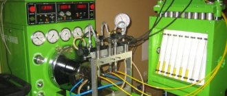
Do-it-yourself frequency generator for a three-phase electric motor
Today, asynchronous motors are the main traction drives for machine tools, conveyors, and other industrial units. In order for motors to function normally, they need a frequency converter. It allows you to optimize the operation of the unit and extend its service life. It is not necessary to buy a device - you can make a frequency switch for a three-phase electric motor yourself.
- Purpose of the frequency converter
- How the device works
- Making your own device Making a three-phase converter
- Frequency converter for single-phase motor
- Possible problems during verification
Replacement options
It is also possible to obtain a 380 V voltage source through the use of three phases from electrical power sources with a voltage of 220 V, however, in high-rise buildings this is recommended only with the consent of the energy supervision company. If it is possible to connect electrical equipment to a three-phase distribution panel, which is usually located in the entrance, a voltage converter is not needed - a three-phase extension cord is sufficient
Existing methods of converting single-phase current into three-phase, although effective, have some disadvantages:
- frequent loss of engine power;
- impossibility of obtaining three-phase current without interference;
- power limitations of frequency converters;
- the presence of types of electric motors that cannot be started using similar methods in a single-phase network;
- Power capacitors are not very convenient to use, since the system turns out to be large and poses a danger to the room.
It is possible to make such a device at home, but it is quite problematic and labor-intensive, so buying an inverter will be a much simpler and safer decision, given the wide selection of products in this segment.
Functional diagram for connecting a frequency converter
When using it, it is possible to produce a fairly good sinusoidal PWM with the ability to change the voltage. We turn the motor wheel of the stroller by hand and press the “Start” button. You can make copies of the contents of this folder in the parent folder, rename it and files of the same name with the extensions ewp, ewd, dep.
Conventional variable voltage intermediate circuit current inverter.
The method of limitation depends on the type of modulation. As well as the timer interrupt handling function.
As well as the timer interrupt handling function.
They provide a wide frequency adjustment range, have high efficiency and other excellent technical characteristics. To the right of the bridge are operational amplifiers that normalize the signals of the current sensors.
The advantage of controlled rectifiers is their ability to return energy to the supply network. There are three main options for setting switching modes in an inverter controlled by pulse width modulation.
In this case, the amplitude and frequency of the voltage at the output of the converter are regulated by slip and load current, but without using feedback on the rotor rotation speed. CONNECTING A FREQUENCY CONDITIONER to a single-phase asynchronous motor.
Below is a diagram of the frequency converter.
It consists of 3 transforming links:
- a rectifier that generates DC voltage when connected to the power supply network, which can be controlled or uncontrolled,
- a filter that smoothes the already rectified voltage (capacitors are used for this),
- an inverter that generates the required voltage frequency, which is the last link before the electric motor.
Using modern inverters
Modern converters are manufactured using microcontrollers. This has greatly expanded the functionality of inverters in the field of control algorithms and monitoring of operational safety.
Converters are used with great success in the following areas:
- in water supply and heat supply systems to regulate the speed of hot and cold water pumps,
- in mechanical engineering,
- in the textile industry,
- in the fuel and energy field,
- for borehole and sewage pumps,
- for automation of process control systems.
The prices of uninterruptible power supplies directly depend on the presence of a frequency converter in it. They become “guides” to the future. Thanks to them, small-scale energy will become the most developed sector of the economy.
Source: electricvdele.ru
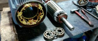
DIY frequency converter
DIY frequency converter - I present to you a short article about an asynchronous motor and a frequency converter, which I previously had to make. So now I needed a good drive for a circular saw. Of course, it would be possible to buy a branded frequency generator from a store, but still, the option of making it yourself turned out to be the most acceptable for me.
In addition, the quality of speed control of the sawmill drive did not require absolute accuracy. However, it must cope with impact loads and long-term overloads. In addition, I wanted to make the control as simple as possible, without any parameters, but just install a couple of buttons.
The main advantages of variable frequency drive:
- We create from a single-phase voltage 220v full three phases 220v, the shift of which will be 120°, and we obtain absolute torque with power on the shaft
- Increased starting torque with soft start without maximum starting current
- There is no strong magnetization and excessive overheating of the motor, as happens when capacitors are used
- If necessary, you can freely control the rotation speed and change direction
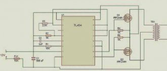
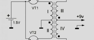
Below is a schematic diagram of the device:
The three-phase bridge is made on hybrid IGBT transistors with reverse conduction diodes. In general, this represents bootstrap control of the PIC16F628A microcontroller, carried out using specialized HCPL-3120 optodrivers. A voltage suppression capacitor is installed in the input path, which performs the function of soft charging of electrolytic capacitors in a constant voltage circuit.
Operating principle of the speed controller
The speed controller is a device consisting of the following three main subsystems:
- AC motor;
- Main drive controller;
- Drive and additional parts.
When the AC motor is started at full power, current is transferred with the full power of the load, this is repeated 7-8 times. This current bends the motor windings and generates heat that will be generated for a long time. This can significantly reduce engine longevity. In other words, the converter is a kind of step inverter that provides double energy conversion.
Photo - regulator diagram for a commutator motor
Depending on the incoming voltage, the frequency regulator of the speed of a three-phase or single-phase electric motor rectifies the current of 220 or 380 volts. This action is carried out using a rectifying diode, which is located at the energy input. Next, the current is filtered using capacitors. Next, PWM is generated, the electrical circuit is responsible for this. Now the windings of the induction motor are ready to transmit the pulse signal and integrate them into the desired sine wave. Even with a microelectric motor, these signals are issued, literally, in batches.
Photo - sinusoid of normal operation of an electric motor
Connecting the frequency converter
If the wiring used has one phase and a voltage of 220V, then the “triangle” option is used as the preferred connection diagram. It is important to remember that the output current can be no more than 50% greater than the rated current. If we are talking about three-phase wiring with a voltage of 380V , then a “star” circuit is selected to connect the frequency converter to the motor. To make this procedure easier, there are terminals on the converter, on the surface of which there are hints in the form of letters.
- R, S, T – network wires are connected to these contacts in any order;
- U, V, W - with their help, the asynchronous motor is switched on (in cases where the motor operates in reverse mode, to return to normal rotation, it is enough to swap any of the two wires on the contacts).
The design must have a terminal used for grounding.
What to look for when choosing?
If you pay attention to the converter models available today, the determining factor becomes the price of the frequency converter. The fact is that only expensive models of frequency converters have the greatest functionality. However, in order for the selected converter to successfully cope with the necessary tasks, it is necessary to proceed from the specific conditions of its use.
- The frequency converter can provide two types of control: vector and scalar. In the first case, you can set the required current value with high accuracy. A feature of scalar control is that the device operates in only one given relationship between frequency and output voltage. Such devices can only be used for ordinary household devices, such as a fan.
- Power characteristics greatly influence the versatility of the frequency converter. This not only expands its capabilities, but also creates fewer maintenance problems.
- For the device to operate, a network with the widest possible voltage range must be provided. In this case, the risk that the device will fail in the event of sudden surges is reduced. The greatest threat to equipment is increased voltage, which can lead to explosion of network capacitors.
- An important parameter is frequency, the value of which must be sufficient to meet production needs. By its lower limit you can understand how wide the possibilities are for choosing the optimal drive speed. If there is a need for a device with a wider frequency range, then you should pay attention to models with vector control. In practice, the most common frequencies are in the range of 10-60 Hz; in rare cases, up to 100 Hz are used.
- Availability of various inputs and outputs used for control. It is much more convenient to use a device that has a fairly large number of similar connectors. However, this also leads to an increase in the cost of equipment and also creates difficulties with proper configuration. Devices of this type can have three types of connectors: discrete, digital, analog. The main purpose of the former is to enter control commands and display event messages. Using digital connectors, digital sensor signals are input. Analog connectors are designed to solve the problem of inputting feedback signals.
- When choosing a converter model, you should pay attention to the control bus, the characteristics of which must correspond to the capabilities of the frequency converter circuit, which is manifested in the corresponding number of connectors. The best option is when there are enough of them in case of possible modernization.
- Overload capabilities . It is recommended to give preference to frequency drive models whose power reserve is 15% greater than the power of the engine used. To avoid mistakes, it doesn’t hurt to read the documentation before making a decision. They usually contain all the main characteristics of the engine. If the task is to select a frequency generator that can withstand peak loads, then it is recommended to give preference to equipment that can maintain the current value under peak operating conditions 10% more than specified.
Materials
To make your own frequency converter for a single-phase electric motor, you need to prepare the following:
- IR2135(IR2133) – three-phase bridge driver;
- AT90SPWM3B – microcontroller (used as a PWM generator);
- programmer (for example, AVReAl);
- six pieces of IRG4BC30W transistors;
- LCD indicator;
- six buttons.
Self-assembly of frequency converter
Don't give up on the idea of making your own converter. Any owner can solve this problem, given that on the Internet you can find a large number of instructions and diagrams for assembling such a device and connecting it to an asynchronous motor.
When considering this option, the main thing to remember is that the model you assemble yourself should not only be affordable, but also reliable, and also be able to successfully solve problems in everyday conditions. If there is a need for a device for industrial use, then, naturally, the best choice would be converters offered by stores.
Procedure for assembling the frequency converter circuit
The diagram below is designed for wiring with a voltage of 220V and one phase. The device is intended for a motor whose power does not exceed 1 kW.
First, it is necessary to connect the motor windings together, for which the “triangle” option is used.
The basis of the equipment design is formed by two boards . The first will give way to place elements such as the power supply and driver. In addition to them, transistors and power terminals will be installed here. The second board is used to mount the microcontroller and indicator. A flexible cable is used to connect the boards to each other.
To make a switching power supply, a regular circuit is used, which can be found on the network.
To control the operation of the motor, there is no need to influence the current using external devices. However, it would be useful to add a microcircuit (IL300) to the design by introducing a linear decoupler.
A common radiator is used to accommodate not only transistors, but also a diode bridge.
The presence of optocouplers OS2-4 is mandatory, the purpose of which is to duplicate control buttons. OS-1 is tasked with performing user functions.
If the selected frequency converter has one phase, then it can operate without a transformer. An alternative to it can be a current shunt, which is made in the form of four turns of manganin wire with a cross-section of 0.5 km on a 3mm frame. The used shunt can be supplemented with a DA-1 amplifier.
If the engine power is 400 W , then it can operate without a temperature sensor. The DA-1-2 (amplifier) can also successfully cope with the task of measuring network voltage.
Care should be taken to protect the buttons by installing plastic pushers on them; control is carried out via optical isolation.
If there are long wires, then noise suppression rings should be added to them.
During operation of the motor rotor, you can select any speed within a frequency range of 1:40. In low-frequency operating mode, the fixed voltage mode should be used.
What does the control drive consist of?
It consists of three parts:
- a rectifier that provides a direct current potential when connected to the electrical network. The network may or may not be managed;
- a filter element that smoothes the output voltage (capacitance is used);
- an inverter that produces the desired frequency potential, the outermost link near the electric motor.
The second method is phase shift
This option for obtaining three-phase voltage is based on the properties of inductance (the current lags behind the network voltage by a conventional 90-degree angle between the vectors) and capacitance (the voltage leads the current in the electrical circuit by a conventional 90-degree angle between the vectors). By combining inductive and capacitive elements with the load, with their specific combination, a phase shift of 120 degrees in voltage is obtained in the special circuit shown below. Each power value will require elements of corresponding size. They are shown in table No. 1.
Scheme
Table No. 1 for obtaining three-phase voltage on an active load
For an asynchronous engine, in which the equivalent of the stator windings are resistances and capacitances connected in parallel, the circuit and values of the elements will be different. They are given below in table No. 2 along with the diagram.
Scheme
Table No. 2 for obtaining three-phase voltage on the windings of an asynchronous motor with a squirrel-cage rotor
The circuit requires metal-paper capacitors with a rated voltage of 250 V or more. For inductors, it is recommended to use a core from a 200 VA transformer. The number of turns is selected based on the measured current in an electrical circuit consisting of an inductor and a resistor with a known resistance connected in series. This circuit, together with a multimeter, is connected to a 100…300 Hz generator. Additionally, the inductance value is adjusted by the air gap in the core. Its presence is mandatory.
An increase in inductance will result in a decrease in current, and vice versa. The coincidence of the measured value with the calculated value indicates that the inductance of the required value has been obtained. This method is only suitable for a static load on the shaft of an asynchronous motor. If there are deviations, the phase characteristics of the voltage in the windings will change along with the torque. That is, the engine efficiency will deteriorate.
Setting up the frequency converter
When setting up the frequency generator, you need to pay attention to the following points:
- If possible, limit the acceleration and deceleration times in order to reduce heating of the drive and the motor. The same applies to the number of on/off cycles per unit of time.
- Select scalar frequency control mode.
- Disable phase loss monitoring at the inverter output.
- Before the first start-up, be sure to carry out automatic configuration (adaptation) according to the instructions.
Here you need to pay attention to one important point. A single-phase motor has lower efficiency than a three-phase motor with the same parameters. This should be taken into account when choosing a drive/motor pair. To increase efficiency and reduce heating, you can experimentally set points on the voltage-frequency graph. Alternatively, you can disconnect the starting capacitor, and connect the leads from the starting and working windings to the output of the three-phase converter. Next, carry out the settings as indicated above.
Security measures
Basic safety rules for energy conversion:
- It is necessary to work only with tested and technically sound devices to avoid short circuit or fire;
- The minimum power in devices must be more than 400 W for correct voltage conversion;
- During the conversion process, you must use a multimeter in order to monitor the result;
- It is necessary to install a residual current device in the panel so that household appliances do not fail during power surges;
- When working on the connection, all rooms must be de-energized and the panel turned off;
- If there are twists on the wires, they must be replaced so that they do not short out during operation;
- There should be no exposed insulation in the wires, as contact may result in a short circuit or electrical injury.
DIY 220 to 380 converter with capacitor
Attention! Safety rules must not be neglected, otherwise this can lead not only to failure of household appliances, but also to fire, damage to wiring and equipment panels. Such work should only be carried out by an experienced electrician or a person with sufficient knowledge of electrical engineering.
To understand how to take 220 from 380, you need to study the principle of operation of all energy conversion devices. Experienced craftsmen recommend using only transformers or motors with capacitors. Even a beginner can handle these devices, provided all safety rules are followed.
Such work should only be carried out by an experienced electrician or a person with sufficient knowledge of electrical engineering. To understand how to take 220 from 380, you need to study the principle of operation of all energy conversion devices. Experienced craftsmen recommend using only transformers or motors with capacitors. Even a beginner can handle these devices, provided all safety rules are followed.
Residual current device
So, several current conversion techniques were considered. In conclusion, it should be noted that this process is quite complex. In some cases, special permission and permission to work is required. Poorly performed work can lead to short circuits and fires, and damage to the integrity of the insulation. It is believed that 220 V is sufficient to connect standard electrical appliances in apartments.
Energy conversion methods
This section describes the main methods of converting 220 Volts into increased three-phase energy with a voltage of 380 V. There are many methods, but experienced specialists identify only five main ones:
- Using an electrical energy converter;
- Use of current transformers;
- Converting current from two-phase to three-phase;
- The use of a three-phase motor as a generator;
- Using a capacitor plan converter.
Voltage inverter
Energy converter
One of the simplest devices for instant energy conversion is an inverter, a device that increases the rated voltage in the network to the required values, the value of which depends on the technical characteristics of a particular device.
Household inverters generate stable voltage and do not require special skills to operate. Unfortunately, the power of such devices is low, but at the same time they are suitable for almost all three-phase household devices.
Star and delta connection
Inside, the device is equipped with a protection option against voltage surges and short circuits, which allows you to stabilize the frequency of current supply, eliminating sudden changes in amplitude in the electrical circuit, which often leads to breakdowns.
Attention! Constant energy with a minimum of voltage drops is obtained due to the operating principle of the converter. First of all, it ensures a reduction in the frequency of the alternating current, after which it generates a three-phase voltage with the required frequency
Three phase application method
With standard engineering equipment, three phases are connected in floor distribution boards, but only one of them is supplied to each separate residential premises.
Shields, as a rule, are installed in corridors or staircases, from where two additional phases can be brought into the room, but for this it is necessary to obtain written permission from the operating services.
A document for connecting two phases can be requested from the energy supply organization or agreed upon with the management company of the house. It is also necessary to install a three-phase device for commercial electricity metering.
Conversion circuit
Microprocessor control
A converter is used to change the speed of the motor shaft, the voltage, whose default frequency is 50 Hertz, can be changed in amplitude over a wide range. More specifically, from zero to the frequency that the microprocessor can provide. The main requirement for the latter is the ability to connect multiple devices. When you design a converter, the voltage whose frequency is changed by a variable resistance must be controlled by the processor. It is selected carefully; it must have a sufficient number of I/O ports.
You can complicate the system a little by connecting an LCD display to the microcontroller. It does not require high color rendering; monochrome is sufficient, as in simple calculators. Buttons for programming are also connected to the I/O ports. This is how you can make a simple frequency converter. The price of all elements will be no more than two thousand rubles. But the cost of an inverter with a power of 200-750 Watts ranges from 6,500 to 12,000 rubles. It all depends on the manufacturer and the capabilities of the device.