So, what else can you do using the assembled Brovin kacher?
What you should not do is bring cameras, phones or other gadgets near it. There is a powerful electromagnetic field around the camera, so any electronics that fall into it can burn out. If you want to make sure of this, the easiest way is to bring a light bulb into the field. It is best to take an energy-saving lamp. It begins to glow no worse than if it were plugged into an outlet. If you have a fluorescent lamp at home, you can add it to the field - the effect will be about the same. If you take a regular incandescent lamp, it will glow differently than usual. The glow appears colored - most of all orange and purple. It looks like a magic ball that you have probably seen in gift shops or souvenir shops. If you have a quartz resonator, you can see a rather interesting glow effect.
It is difficult to find practical application for such a device as the powerful Brovin Kacher. In fact, I assembled the kacher solely as an experiment. Other enthusiasts are usually guided by the same reason. Perhaps you will find some more useful use for the assembled kacher. If you succeed, be sure to share with us your build option and how you can benefit from this interesting device.
Write comments, additions to the article, maybe I missed something. Take a look at the site map, I will be glad if you find anything else useful on my site.
Description of the electrical circuit assembly
DIY search magnet
The author of the invention recommends using a bipolar transistor KT902A or KT805AM (however, you can assemble a Brovin kacher on a field-effect transistor). The semiconductor element must be mounted on a powerful radiator, having previously been lubricated with thermal conductive paste. You can additionally install a cooler. It is permissible to use constant resistors, and exclude capacitor C1 altogether. First, you should wind the primary winding with a wire of 1 mm (4 turns), then the secondary winding with a wire no thicker than 0.3 mm. The winding is wound tightly turn to turn. To do this, we attach its end to the beginning of the pipe and begin to wind it, coating the wire with PVA glue every 20 mm. It is enough to make 800 turns. We fix the end and solder an insulated conductor to it
The windings should be wound in one direction, it is important that they do not touch. Next, you need to solder a sewing needle into the upper part of the pipe and solder the end of the winding to it
Next, we solder the electrical circuit and place it together with the radiator inside the plastic pipe. This elementary device is Brovin’s kacher.
Chapter II. Practical part
2.1. Assembling the Brovin quality camera installation
Let's consider the stages of assembling this device at home.
Basic elements of Kacher:
- inductor (secondary winding);
- inductor (primary winding);
- pay.
- frame
The diagram that I followed during assembly is as follows:
Rice. 1
Installation details:
- Polyvinyl chloride (PVC) pipe with a diameter of at least 25 mm and a length of 30 cm (the glow range of the light bulbs will depend on this). I used a pipe with a diameter of about 55 mm.
- To make the secondary winding of the kacher, I used copper wire coated with a double layer of varnish and 0.20 mm in diameter. It should be wound on the pipe, at least 1500 turns. (My copy of the kacher has about 2000 turns wound on it.) Every few centimeters I applied glue to fresh turns, otherwise the winding might get lost and tangled.
- To make the primary winding, I needed a copper wire with a diameter of 0.5 cm, which must be wound around the secondary coil. It is necessary to make about 4 turns. We wind all the windings in one direction! We install and secure the pipe with the winding on plywood or a board, stretch the primary winding by 1/3 of the secondary. The windings must not touch! Then we fuse a metal wire the size of a sewing needle into the pipe from above and solder the end of the winding to it. Next, we screw the radiator for the transistor to the platform next to the coils, coat the base with heat-conducting paste and screw the transistor to the radiator with a metal socket.
To make the board I needed the following radio components:
- throttle,
- non-polar capacitor (1000 v 3000 μF),
- 2 resistors (2.2 kOhm and 150 Ohm),
- NPN transistor, the more powerful the better (they can be found in a regular PC power supply or on the board of old tube TVs).
Everything is mounted as shown in the diagram (Fig. 1). Solder the power wires.
Next, I made a casing for the kacher from fiberboard. The power button was placed on the top panel and secured with hot glue. The body and coil were coated with colorless varnish. The design is ready! (Fig. 2)
Rice. 2
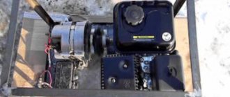
This device must be connected to a power supply with a voltage from 12 to 38 v, which I also designed myself (Fig. 3)
Rice. 3
Checking the quality is carried out by placing a fluorescent light bulb on the secondary winding; if the connection is correct, it will light up. When the secondary winding is touched by a metal object, there will be a discharge between them. If the kacher does not work, then you need to check whether the circuit is assembled correctly or try changing the ends of the primary winding.
2.2. Effects observed during the operation of the Brovin quality camera
Let's consider the effects observed during the work of Kacher Brovin, which I constructed at home.
- We bring a fluorescent lamp to the secondary winding, we see that it lights up. (Fig. 4) If you bring a gas-discharge lamp to the kacher, it also begins to glow. (Fig. 5) The same effect is observed with other similar lamps. Also in a regular incandescent lamp you can see the so-called glow discharge. (Fig. 6)
Rice. 4
Rice. 5
Rice. 6
- During operation, the kacher creates beautiful effects associated with the formation of various types of gas discharges - a set of processes that occur when an electric current flows through a substance in a gaseous state. Brovin's quality ranks:
- Streamer (from English Streamer) - dimly glowing thin branched channels that contain ionized gas atoms and free electrons split off from them. Streamer - visible ionization of air (glow of ions) created by an explosive - Kacher field. (Fig. 7)
Rice. 7
- Arc discharge—occurs in many cases. For example, with sufficient transformer power, if a grounded object is brought close to its terminal, an arc may light up between it and the terminal. Sometimes you need to directly touch the terminal with an object and then stretch the arc, moving the object to a greater distance. (rice.

Rice. 8
Switching power supply and power switch
In order to make the assembled Brovin network camera more mobile, it is better to install a connector in the case that allows you to connect a wire from the power supply to it. Surely, almost everyone has broken equipment in their closet or garage, from which such a nest can be dismantled. If not, then it can be purchased at any radio electronics store; the cost of such goods is low.
The connector also needs to be fixed in the body of the soap dish, for which a slot was made at the end according to the dimensions.
This is how the connector for connecting the power supply was neatly placed
After the wires were soldered to the connector contacts, the socket was also fixed with hot glue. Now there was no need to be afraid that when the plug was pulled out, the connector would fall out.
We fix the power connector in the body of the soap dish
Connecting power through a switch to a transformer
Next you should be very careful. We solder the negative wire coming from the power connector to the emitter (the left contact of the bipolar transistor). You cannot mix it up here, otherwise the assembled Brovin network camera will not work.
Connect the negative power wire to the emitter
The positive wire goes directly to one of the toggle switch contacts. I didn’t take a photo of this step, everything should be clear here. And from the second contact of the toggle switch, the jumper will go to the contact of the film capacitor, which is connected through a 2.2 kOhm resistor to the base of the bipolar resistor (right contact).
We connect the second contact of the switch to the base of the transistor through a resistor
All that remains is to solder the end of the secondary winding that goes into the housing, and you can move on to the primary. We connect it directly to the base of the bipolar transistor, bypassing the resistor. In fact, the scheme is elementary and understandable even to a middle school student. Of course, such a simple device will not be capable of producing long lightning bolts, but even the minimum with such a simple scheme can already be called progress for a beginner.
Solder the end of the secondary winding to the base of the bipolar transistor
Connecting the primary winding of the transformer
Here you need to prepare two pieces of wire. At one end of each of them there should be an alligator clip for easy connection. One of the wires is soldered to the output contact of the toggle switch. Color coding does not play a role here. The fact is that if all the elements are functioning normally, the winding of the coils is done in one direction, and the Brovin kacher still does not work, then the only step to correct the defect will be to replace the polarity of the voltage supply to the primary of the transformer. In other words, it is possible that the crocodiles will have to be swapped.
Using a wire with a crocodile we connect the output contact of the toggle switch and one of the ends of the primary winding
The second alligator wire will connect the other end of the winding and the middle terminal of the bipolar transistor, called the collector.
The second wire will connect the remaining end of the primary winding to the collector of the bipolar transistor
All that remains is to assemble the Brovin Kacher we installed and begin testing its performance.
This is such a neat kacher we got
Signs that the Brovin kacher is functioning
How to check and repair an electric motor commutator yourself
After applying power to the transformer, it is better to dim the light - this way the effect will be better visible. At the tip of the secondary winding left outside, you can see a small bluish light. If you bring ordinary CFLs (energy-saving or fluorescent lamps) to the transformer, they will begin to glow without any connection.
This is the effect that kacher has on CFLs and conventional fluorescent lamps
A discharge will occur in the incandescent lamp, which is also quite interesting.
And this is how an incandescent lamp behaves next to a Brovin quality driver
Moreover, if you bring a neon lamp to the transformer, the glow will be much brighter. But the most interesting thing is that as soon as you press paper against the tip of the secondary winding, it lights up almost instantly. That is why you should not put your fingers near it. Naturally, a person will not feel an electric shock, but it is quite possible to get skin burns.
The paper flashes from the discharge quite quickly
What is a Tesla coil and why is it needed?
How to make a transformer with your own hands?
As noted earlier, a Tesla coil is a resonant transformer. The purpose of a transformer is to change the voltage value of an electric current. These devices are respectively lowering and increasing.
Read more about transformers, their general structure and purpose in our separate material.
From an electronics point of view, a Tesla coil consists of two windings without a common core and with a different number of turns. Tesla transformer is a step-up transformer. The voltage at the output of such a transformer increases hundreds of times and can reach values of the order of a million volts.
Tesla's invention not only works, but works very spectacularly. By turning on the transformer, you can observe spectacular discharges (lightning), the length of which reaches several meters.
A simple kacher circuit
Below you see the simplest, but very powerful caching scheme. It is known to every experienced electronics engineer, and even a beginner can assemble it.
Kacher includes three component modules:
- Directly the pitcher himself;
- Power supply;
- Breaker or control unit.
A chopper is needed to regulate the pulse frequency. The pulses arrive at the pnp semiconductor, which opens/closes the pn junction, “listening to the clock” of these pulses. During this seemingly extremely short time, a spark manages to run across the terminal.
In other words, the operation of the device is described as follows:
- In two directions, the current flows to the PNP semiconductor and then to the breaker;
- Voltage occurs in the power source circuit;
- The chopper is activated and sends a pulse to the transistor gate;
- The gate of the semiconductor opens the pn junction;
- Current flows through the kacher circuit;
- The circuit is closed.
What does a Tesla coil consist of?
Before assembling the Tesla coil, let's look at its components and shape.
Tesla coil structure
Toroidal figures: what are they?
The Tesla coil is made in the shape of a Torus (toroidal figure, toroid).
It's better to look once than to try to imagine. The figure below shows toroidal surfaces.
This is what a classic toroidal figure looks like
The toroid is an important component of the Tesla coil and is usually made of aluminum corrugation. As part of this device, it performs the following functions:
- reduces the resonant frequency;
- accumulates energy before streamer formation;
- creates an electrostatic field that repels the streamer from the secondary winding of the transformer.
By the way, you can read about what a streamer is in our separate article on lightning.
You can't help but notice the funny play on words. In Norse mythology, Thor is the god of thunder and lightning. The component of a Tesla coil, due to which a discharge (lightning) is formed, is a torus, or toroid.
Secondary winding
The secondary winding is the main component of the Tesla coil, which is also simply called the “secondary”. The winding, as a rule, contains about 800-1200 turns, and it is wound on PVC pipes, which can be bought at a regular hardware store.
Based on the required number of turns, the diameter of the winding wire is selected. The standard ratio of the length of the secondary winding of the coil to its diameter is 4:1 or 5:1. To prevent the coils from spreading, they are coated with varnish.
Primary winding and protective ring
The primary winding (or primary) of a Tesla coil must have low resistance because it will carry a lot of current. It is usually made from wires with a cross-section of more than 6 millimeters. Also, copper pipe for air conditioners is often used as the primary winding.
The shape of the primary winding is cylindrical, flat or conical.
The protective ring is an open flat turn of grounded copper wire. The ring is installed so that the toroid streamer, once in the primary winding, does not damage the electronics.
How to assemble a Brovin kacher with your own hands
If, after reading the article, you are interested in this device, you can assemble it yourself. The device is so simple that even a novice radio amateur can make it. The Brovin Kacher (diagram shown below) is powered by a modified 12 V, 2 A network adapter and consumes 20 W. It converts an electrical signal into a 1 MHz field with an efficiency of 90%. For assembly we need a plastic pipe 80x200 mm. The primary and secondary windings of the resonator will be wound on it. The entire electronic part of the device is located in the middle of this pipe. This circuit is completely stable, it can work for hundreds of hours without interruption. The self-powered Brovin Kacher is interesting in that it is capable of lighting unconnected neon lamps at a distance of up to 70 cm. It is a wonderful demonstration device for a school or university laboratory, as well as a tabletop device for entertaining guests or performing magic tricks.
The concept of ether and Tesla's ideas
Now we know what a Tesla coil consists of. But what is the history of this invention? To answer this question, it is worth understanding what ether is.
At the moment, the theory of the ether is not used in modern physics, since after the advent of the theory of relativity, the need for the concept of “ether” simply disappeared.
However, new views on the concept of ether are emerging, and it should not be completely written off. Many scientists are still debating whether ether exists or not, and a new section has even appeared in physics that studies this issue (ether dynamics).
Nikola Tesla proved the existence of ether with his experiments. The scientist had an idea to use ether as a source of energy. Thus, Tesla wanted to abandon wired transmission of energy and transmit electricity throughout the world wirelessly through the ether. To do this, it was planned to install two giant coils at the Earth's poles.
Unfortunately, the direction Tesla chose was not developed at a deeper level. In addition, he was considered a strange scientist who never wanted to take the path of seeking the economic benefits of his research. In addition, another era was coming - the time of vacuum inventions.
Many of Tesla's archives were lost under mysterious circumstances. Even if Tesla found out how to obtain a practically inexhaustible source of energy, this information is not available now. The rare genius of Tesla was ahead of his time, and the world was simply not ready for his ideas.
Introduction
At least once in our lives, we hear on TV or on the Internet about the great genius Nikola Tesla and his coil, which can transmit electricity through the air.
But no one thought that at home you could assemble a similar device called the Brovin Kacher. The relevance of the topic is due to the fact that the problem of finding clean energy in the 21st century is acute. In the modern world, humanity needs electricity every day. It is needed both by large enterprises and in everyday life. A lot of money is spent on its production. And that's why electricity bills are rising every year.
Object of study: physical phenomenon of contactless energy transfer.
Subject of research: a device that is capable of transmitting electricity without wires.
Hypothesis: Brovin's Kacher can be assembled at home at minimal cost.
Goal: to produce a working model of the Brovin Kacher and consider the possibilities of its practical application.
Tasks:
- study reference and scientific literature on this topic;
- consider the device, principle of operation and application of the Brovin kacher;
- create a working model of the Brovin quality player;
- analyze the knowledge gained on this topic.
Research methods:
- working with methodological literature
- comparative analysis
- observation
- experiment
By-effect
An analysis of the properties of the assembled circuit revealed some inconsistencies in its operation with generally accepted concepts. It turned out that the signals received at the electrodes of the semiconductor transistor, measured with an oscilloscope relative to the positive and negative poles of the voltage source, always had the same polarity. So, the npn transistor produced a positive signal at the collector, and pnp - a negative one. It is this effect that makes Brovin’s kacher interesting. The device circuit contains inductance, which during operation of the device has a resistance close to zero. The generator continues to operate even when a powerful permanent magnet approaches the core. The magnet saturates the core, as a result the blocking process must stop due to the cessation of transformation in the feedback circuit of the circuit. At the same time, no hysteresis was detected in the core; it could not be detected using Lissajous figures. The amplitude of the pulses at the collector of the transistor turned out to be five times higher than the voltage of the power source.
It is important
The description of the Brovin kacher effect in nearby space may turn out to be a way of reversing the spins of the atoms of surrounding substances. This is indicated by the author of the invention in an experiment with enclosing the device in a sealed glass vessel, from which the air was pumped out to reduce the pressure level in it. As a result of the experiment, there is no superunit effect that would allow us to classify the device as a perpetual motion machine (with the exception of real experiments on energy transfer through a wire). This was first demonstrated by Nikola Tesla. However, possible incorrect readings of power metering devices are explained by the pulsed, very inharmonious nature of the current flow in the power consumption circuits of the power supply. While measuring instruments such as testers are designed for either direct or sinusoidal (harmonic) current.
Where should I put it all?
The eternal problem is a good body. Despite a couple of computer power supplies in which some install such circuits, I decided not to use metal. For better electrical safety. After all, we’re not assembling a flashing light!
After some thought, I took as a basis a piece of plastic pipe 120x200 mm, from a kitchen hood. It's round and looks good. It will contain a circuit, a field-effect transistor with a radiator, and a primary circuit. And a secondary with a sharp copper knob will stick out from above.
The top of the case is closed with a lid from a box in which seaweed is sold.
A slot is made in the lid for the coil, and so that they do not look inside, it is covered with black self-adhesive tape.
The coils were attached to the body through a fiberboard strip left over from the renovation of the balcony, with mounting posts for connecting the three necessary wires.
When designing, keep in mind that the radiator for the transistor requires more than a pack of cigarettes; a small one will get very hot, so you won’t run the heater for a long time. I stopped at 50x100x5 mm, but after 10 minutes it becomes hot.
The second most important thing, after the coil, is the choke. A lot depends on him
A choke inductance of more than 1 Henry and a current of 1 ampere are required. I tried primary ones from network transformers: up to 50 watts it doesn’t work at all, 50-100 watts is good, 100-200 is excellent. It was just a pity to install such powerful ones, so I limited myself to the 60-watt TN42.
We place everything in a case on a metal base, to which a choke, a radiator, and, if anyone wants, a printed circuit board are screwed. I didn’t make it - I assembled it by hanging it.
The outside of the body is also covered with self-adhesive tape, and the coil is wrapped with black electrical tape. I was afraid that it would work poorly with her, but it worked out.
After placing it in the case, we turn it on again not directly to 220V, but through a fuse lamp. There may be no sparks with it, but the rumbling of the circuit and the glow of the neon light near the coil will tell you that everything is all right.
Unknown capabilities of semiconductor elements
Brovin's kacher is a type of generator assembled on a single transistor and operating, according to the inventor, in abnormal mode. The device exhibits mysterious properties that date back to the research of Nikola Tesla. They do not fit into any of the modern theories of electromagnetism. Apparently, Brovin's kacher is a kind of semiconductor spark gap in which the discharge of electric current passes through the crystalline base of the transistor, bypassing the stage of formation of an electric arc (plasma). The most interesting thing about the operation of the device is that after a breakdown, the transistor crystal is completely restored. This is explained by the fact that the operation of the device is based on reversible avalanche breakdown, in contrast to thermal breakdown, which is irreversible for a semiconductor. However, only indirect statements are given as evidence of this mode of operation of the transistor. No one, except the inventor himself, has studied the operation of the transistor in the described device in detail. So these are just assumptions by Brovin himself. So, for example, to confirm the “black” mode of operation of the device, the inventor cites the following fact: they say, no matter what polarity the oscilloscope is connected to the device, the polarity of the pulses shown by it will always be positive.
The device and principle of operation of the Brovin Kacher
The Brovin Kacher was invented in 1987 by Soviet radio engineer Vladimir Ilyich Brovin as an element of an electromagnetic compass. Engineer Brovin V.I. Higher education – graduated from the Moscow Institute of Electronic Technology in 1972. In 1987, he discovered inconsistencies with generally accepted knowledge in the operation of the electronic circuit of the compass he created and began to study them. He made many inventions at home. One of them is Kacher Brovina.
Let's take a closer look at what kind of device this is. Brovin's kacher is a type of generator assembled on a single transistor and operating, according to the inventor, in abnormal mode. The device exhibits mysterious properties that date back to the research of Nikola Tesla. They do not fit into any of the modern theories of electromagnetism. Apparently, Brovin's kacher is a kind of semiconductor spark gap in which the discharge of electric current passes through the crystalline base of the transistor, bypassing the stage of formation of an electric arc (plasma). The most interesting thing about the operation of the device is that after a breakdown, the transistor crystal is completely restored. This is explained by the fact that the operation of the device is based on reversible avalanche breakdown, in contrast to thermal breakdown, which is irreversible for a semiconductor. However, only indirect statements are given as evidence of this mode of operation of the transistor. No one, except the inventor himself, has studied the operation of the transistor in the described device in detail. So these are just assumptions by Brovin himself. So, for example, to confirm the “black” mode of operation of the device, the inventor cites the following fact: they say, no matter what polarity the oscilloscope is connected to the device, the polarity of the pulses shown by it will always be positive.
Maybe kacher is a type of blocking generator? There is also such a version. After all, the electrical circuit of the device strongly resembles an electrical pulse generator. Nevertheless, the author of the invention emphasizes that his device has a non-obvious difference from the proposed circuits. It provides an alternative explanation for the occurrence of physical processes inside the transistor. In a blocking oscillator, the semiconductor periodically opens as a result of the flow of electric current through the feedback coil of the base circuit. In quality, the transistor must be permanently closed in a so-called non-obvious way (since the creation of an electromotive force in the feedback coil connected to the base circuit of the semiconductor can still open it). In this case, the current generated by the accumulation of electrical charges in the base zone for further discharge, at the moment the threshold voltage value is exceeded, creates an avalanche breakdown. However, the transistors used by Brovin are not designed to operate in avalanche mode. A special series of semiconductors has been designed for this purpose. According to the inventor, it is possible to use not only bipolar transistors, but also field-effect and radio tubes, despite the fact that they have fundamentally different physics of operation. This forces us to focus not on research on the transistor itself in the quality, but on the specific pulse mode of operation of the entire circuit. In fact, Nikola Tesla was engaged in these studies.
Kacher Brovina is an original version of an electromagnetic oscillation generator. It can be assembled using various active radioelements. Currently, when assembling it, field-effect or bipolar transistors are used, less often radio tubes (triodes and pentodes). Kacher is a reactivity pump, as the author of the invention, Vladimir Ilyich Brovin, himself deciphered this abbreviation. The Brovin Kacher is powered by a modified 12 V, 2 A network adapter and consumes 20 W. It converts an electrical signal into a 1 MHz field with an efficiency of 90%. One of the parts of this device is a plastic pipe 80x200 mm. The primary and secondary windings of the resonator are wound on it. The entire electronic part of the device is located in the middle of this pipe. This circuit is completely stable, it can work for hundreds of hours without interruption. The Brovin Kacher with self-powering is interesting in that it is capable of lighting unconnected neon lamps at a distance of up to 70 cm.
How to make a kacher with your own hands
which is understandable and simple even for a beginner, kacher can become your “entrance ticket” to the fascinating world of radio electronics (if, of course, you are not already doing such homemade products).
What you need to prepare to assemble the device:
- Two arms. Maybe even not very experienced ones, a little “crooked”;
- Wire with a cross section of 0.25 mm. It is fashionable to take wire from the transformer secondary winding;
- PNP type transistor. (KT902-A, KT805-AM, KT808, KT805-B, etc.);
- Several resistors with any resistance;
- Electrolytic capacitor 1,000-10,000 μF;
- Power supply for 12-30 V, with a current in the range of 1-1.5 A.
More information about the radio components used
The above “set” is standard. Moreover, if suddenly you don’t have any radio element on hand, you can always replace it with another one. The main thing is not to exceed the limit of 10-30% of each denomination. The generator must operate within 150 Hz.
The power supply voltage of the camera is 220 V. To protect the device, it is recommended to use a 5 A fuse. The device operates from 310 V, so we need to include a 500 V and 10 A diode bridge in the circuit. A second bridge is installed in front of the breaker - 50 V and 1 A If you are replacing a transistor, choose a more powerful one. The capacitor circuit will need to be adjusted yourself, but the best option is 0.5-1 µF.
Regarding the coil. It requires two wires. The primary coil is wrapped with 2 squares of wire, with a minimum number of turns (3-5). The secondary winding is implemented using PLSHO wire or similar. The number of turns is about 1,000. The wire can be secured with tape, but it is better with glue.
The trimming resistor for the quality device must be selected at 15-40 Ohms. If you can’t find this radio component, take a regular resistor with a resistance within the same limits.
Let's start assembling the camera
First you need to assemble the primary coil. To do this, we prepare a PVC or cardboard pipe with a diameter of 5-8 cm, and a copper wire with the largest cross-section. Further:
We form 4 turns on the pipe
It is important to make them not very dense; We take out the pipe and carefully stretch the wire so that the height of the winding is 10-15 cm. We make the secondary coil 3 times higher
For this you need to take a thin wire. The number of turns is about a thousand. To prevent the wire from getting tangled on the rod, in some places you need to coat the wires with glue or varnish. We mount the first coil around the second coil. Each of the windings should “look” in the same direction
We make the secondary coil 3 times higher. For this you need to take a thin wire. The number of turns is about a thousand. To prevent the wire from getting tangled on the rod, in some places you need to coat the wires with glue or varnish. We mount the first coil around the second coil. Each of the windings should “look” in the same direction.
The wound pipe must stand strictly vertically. It must be fixed on a horizontal stand. For example, on any durable wooden surface. Next, you need to assemble all the other radio elements according to the diagram. After assembly, you need to check the connection diagram.
If the cacher does not work
If the device does not work the first time, you need to swap the contacts of the primary coil. If this does not work, we check the transistor, then test the conductivity of the coils.
You don’t have to be afraid and change the number of turns or position on the primary coil. This must be done until there is a noticeable effect. These are all problems that can arise.
Settings
To adjust the quality, we have a tuning resistor R1 (or several constants, with different resistances). It is worth installing copper radiators on the transistors so that during operation they do not get too hot and eventually burn out.
Scheme of the driver from Brovin
The second scheme is proposed by the inventor himself. Here she is:
Here 2-3 coils and a wide variety of transistors can be used. The device is powered by a 1.2 V battery. The coils have a diameter of 5 cm. The number of turns on coils 1 and 3 is 60, on coils 2 – 30. Transistors used: 9018, 9014, KT315, etc.
To achieve the greatest effect with such a circuit, you need to place coils 2 and 3 as close to each other as possible. If you place all 3 coils next to each other, the brightness of the LED will be maximum.
Kacher Brovina from A to Z
Kacher Brovina from A to Z
In 1987, while developing a compass using the classical blocking oscillator circuit, the author discovered a physical phenomenon that had not been described anywhere. In the presence of a ferromagnetic core, there was no hysteresis in the transformer, and the output voltage pulses exceeded the amplitude of Usupply by 30 or more times. The compass worked as a fluxgate, and information about the relationship of the device to the XYZ spatial axes could be taken in the frequency, which varied by a factor of 5, and in the voltage amplitude of the output pulses, which varied within 30%.
The use of such a fluxgate in various devices, such as a current meter in a circuit along the surrounding conductor, and any other magnetic field, can be used in many applications. The author began to examine circuits containing inductance, starting from the core, and it turned out that the core had nothing to do with it, everything happens the same way without a core. Any circuit consisting of at least one inductor and a transistor can become a pulse generator. The peculiarity of such a generator is the phenomenal transfer of energy in a transformer connection in the absence of a core. In the secondary circuit, you can get tens of volts, hundreds of milliamps from a low-power transistor, and this means that a new automation tool has been obtained that can decouple galvanically connected circuits. You can convert non-electrical quantities meters, degrees, grams, atmospheres, etc. into volts amperes hertz. The author used one of the circuits to create an electrical output to a conventional dial pressure gauge. Equipped three pressure gauges and organized tests at the Gazprom testing station. This was 1993. Until 1987, the author worked in the central office of Gazprom, and the author was still remembered, although after 1987 the author no longer worked there. After a business trip to Afghanistan through Gazprom, the author had money, and the author worked at home only in the inventive part. By order of the Main Directorate of Gazprom, three-day tests of 3 pressure gauges were carried out which showed that at +_50 degrees of temperature, deviations in electrical output readings remain within class 1.5, and the repeatability of measurements is ideal. There are nonlinearities at the beginning and end of the scale, this is due to the fact that everything was done at home according to geometry, without pumping pressure into the pressure gauge. It was not possible to introduce a pressure gauge into Gazprom or even try it in combat conditions; an explosion safety certificate was required, and this was then done in Ukraine. The author patented the resulting device in 1993 as the “Brovin Sensor for Measuring Displacement” and received patents for 7 applications: pressure gauge and other sensors. The review lasted 4 years in different departments. The author's name was assigned, contrary to the law, as a distinctive feature. Having received the first patent “Manometer”, he unsuccessfully tried to implement it in other places of the Heating Network, State District Power Plant, and Manometer plant. At that time, the author did not understand the operating principle of the device at all. But the techniques and methods for obtaining the desired result worked out. This is a transistor generator circuit in which the caching process occurs. Its peculiarity is that theoretically it should not work, since the base is short-circuited and there is no source of base current. However, it works with PIC, OOS, and no OS. (a) The base and emitter currents act in opposite directions (a decrease in the base causes an increase in the emitter), whereas normally an increase in one should cause an increase in the other. (b) A negative current in the base indicates that the voltage at the emitter is higher than at the base, i.e. >0.7V. There is always a voltage of 0.7V in the base (even if the power supply to the entire cascade is 0.2V). (c) At the same time, a voltage of about 0V is observed at the collector, and both junctions are forward biased. (d) The voltage on the collector corresponds to the state of the open transistor, although by all indications the transistor cannot be open. (e) Voltage pulses at the base and collector measured relative to – and + of the power source have the same sign. (f) The voltage pulses in the collector and base do not correspond in time to the current. (g) The circuit operates in a wide range of supply voltages from 0.2V (on a silicon transistor) to the melting temperature of the plastic transistor case, from an increase in voltage at the power source, and an increase in current according to Ohm’s law. (h) In transformer connection with the base and collector coils, a voltage and current exceeding the voltage of the power source can be obtained. All (a, b, c, d, e, f, g, h) patterns require explanation. (d) Initially, it was possible to explain why the voltage at the collector is about 0V. The increasing collector current (emitter I31) creates a back EMF of self-induction (UE = 0) directed towards the voltage of the power source. In the printed work “V.I. Brovin “The phenomenon of transfer of energy of inductances through the magnetic moments of a substance located in the surrounding space, and its application,” a version of the nature of self-induction was presented as the expenditure of energy from a power source on the mechanical rotation of the magnetic moments of the atoms of the substance surrounding the inductance. In the event of a circuit break, the magnetic moments return to their original state and act on the conductor through which current flowed before the break, like a moving circuit with current, exciting a self-inductive emf in it. The increase in current, initially when the circuit is connected, and when it is broken, excites currents and voltages in the secondary circuits similar to those observed in the primary ones. (b, c) The voltage in the base of the order of 0.7 V that exists in all cases with kachers can be explained by the following experiment related to the PN junction and inductance. This pattern is observed in all combinations of PN junction and inductance. At the end of the pulse, a voltage of 0.7-0.5V and a falling current are observed at the anode of the diode, completed by an oscillatory process. In the transformer connection at this time the sign of the voltage changes to the opposite, but the direction of the current does not change. At the moment when the energy sources are reset to zero, an oscillatory process similar to self-induction is observed, which is also reset to zero. At the first stage (cells 2,3), the diode is unlocked, the current increases normally. The pulse is interrupted before entering the stationary mode. The carriers accumulated during the pulse must be resolved, and with a resistive load in the switches this takes nanoseconds. In our case, the pulse takes 10 μS, and the resorption takes 20 μS, and all this time the PN junction remains a source of voltage, despite the fact that at the end of the pulse the sign of the self-induction EMF is PN. The explanation is as follows. The carriers accumulated in the base during the pulse are not able to overcome the potential barrier of self-induction of the trailing edge. The magnetic moments here do not instantly reverse to their original state. There is a decrease in the concentration of carriers in the crystal, which means a partial transition to the underlying energy level. Some of the carriers diffuse through the shunt to 0V. The rest move to the underlying energy level, and instead of a photon, they release another type of energy expressed in Volts. When there are no free carriers left in the crystal, which means a complete break in the circuit, the remaining magnetic moments return to their original position, and a weak pulse of self-induction emf is now released, which oscillates in response to the barrier capacitance. Let's consider the same thing, but with a transistor.
In steady state, it is difficult to analyze the processes occurring in the camera. This should be done in the transition process from the beginning of the action. In silicon transistors, the quality process is observed starting from 0.08V, but this should be achieved specifically. Typically, the quality process in silicon transistors starts at 0.2V. Here, for clarity, a process starting at 0.3V is demonstrated. The circuit operates from voltages of 0.3V - 0.4V. The square pulse generator (RPU) unlocks the base junction with a single pulse. In Fig. 1, the GPI pulse increases Ub to 0.8V. In Fig. 2, while Ui was passing, Uk decreased by 0.1V and after the end of the GPI pulse (the transistor should turn off, and Uk should reach the Upit level), Uk further decreased to almost 0V. Ub see Fig. 1 in this interval remained at the same level. Then a damped oscillatory process occurs. All these events occur at Upit = 0.3V. If Upit is increased to 0.4V, the oscillatory process will become undamped (Fig. 3.4). Ie Fig. 4 is observed on the shunt, which is interrupted when pulses occur in the collector. Following the current Ii of the pulse of Fig. 4, a “leakage current” appears, “resorption” (both terms mean the same thing), indicating a state in which Uk decreased, and Ub Fig. 3 remained at the same level. In the future, this is a periodically repeating process which, with increasing Upit, acts with increasing intensity. The explanation is this. The appearance of current in the crystal caused by emitter injection is interrupted with the transition of Ui to 0V. Free carriers are carried out through the collector and Uk = Upit - E. In the transistor crystal, a voltage drop occurs at the collector 0V on the base 0.7V at the emitter >0.7V, and therefore the base current has a negative sign. This continues until all the carriers are carried through the collector and the crystal for a certain time interval begins to have a resistance equal to infinity, which in turn will cause the magnetic moments to return to their original state, which is reflected in the form of voltage pulses at the end of each period. a) Base current is the transfer of excess carriers from the emitter region to the middle part of the transistor crystal through the base inductance. e) Pulses on the base or collector, measured relative to the plus or minus of the power source, are the same in sign because they are measured relative to the direction of the current that caused them. All this can be repeated with a bias in the base from the power source of 0.6V. At the collector, the voltage changes from 0.3V to 1.3V and 11.3V and we get the following result. This method of exciting the process quality allows you to combine any transistors with any combination of inductances over a wide range of supply voltages. In this case, the rule of positive feedback should be observed. The beginning of the base coil is located at the base, the beginning of the collector coil is always located at the power source. The Kacher process can be implemented using field-effect transistors, bipolar transistors, and radio tubes. A kacher should be considered a device in which alternating connections and breaks of the electrical circuit occur in each individual period, without entering the stationary mode used by all. In the usual case, this cannot be done with an inductive load in one interval. This is what happens, for example, in the lamp version. With a transistor everything will be the same, but it’s more difficult to explain. In this case, a new circuit break can be obtained only by repeating two events - opening and closing the lamp. Kacher is implemented in any conventional schemes with OB, OE, OK, and exotic ones. Here is an example of an exotic circuit.
This circuit operates at 0.7V and produces 40V pulses that can charge capacitors and batteries. To the question “Why all this”? The answer is a new way of transmitting information through the mechanical rotation of the magnetic moments of atoms (known methods are sound, light, electrical circuit, electromagnetic wave). This is an absolute sensor. This is a DC transformer. There is a strong opinion that a kacher is a Tesla transformer in which the role of a capacitor is played by a power source, and the role of a spark gap is played by a transistor crystal. A kacher is a Tesla transformer of continuous action that transmits energy through one wire, creating radiation that is not electrical, not magnetic, not gravitational. On the Internet, the words “Brovin’s kacher” mean a single scheme. It is used as a source of high voltage voltage. Generator Tesla-Brovin-Mag. Magician is a nickname on the Internet. Judging by the descriptions and displays, the GTBM can illuminate the filament of an incandescent lamp at several separate points. LDS illuminate in a free state. Divide the water into its components, and it can be set on fire. The current from the GTBM passes through any insulators. The power measured at the output is higher than at the input, i.e. Efficiency is more than 100%. From numerous experiments (for example, an LED lights up connected by one leg) it follows that the circuit absorbs additional energy from the surrounding space, but it is not yet clear why. The transformer properties of the kacher make it possible to create an absolute sensor that converts non-electrical quantities meters degrees into Volts, Amperes, Hertz directly without conversion. With such a circuit powered by 4V, in the secondary circuit you can get 20V, 2mA, when one coil is removed from the other by 15 - 30 mm. Coils can be of any size from microns to meters.
The transformer properties of the pumps allow the 5V control circuits to be galvanically isolated from the 220V control circuits. The output signal allows you to control a thyristor and transistor in a transformer connection.
Kacher improves the properties of LEDs - they heat up less, do not degrade, and do not require separation by resistors.
With such a circuit powered by 4V, in the secondary circuit you can get 20V, 2mA, when one coil is removed from the other by 15 - 30 mm. Coils can be of any size from microns to meters.
The transformer properties of the pumps allow the 5V control circuits to be galvanically isolated from the 220V control circuits. The output signal allows you to control a thyristor and transistor in a transformer connection.
Kacher improves the properties of LEDs - they heat up less, do not degrade, and do not require separation by resistors.
Winding the coils: making a step-up transformer
For the secondary coil you will need a copper wire with a diameter of 0.15 mm. It can be taken from the magnetic starter by disassembling the retractor coil. It is most convenient to wind on a regular plastic pipe. When winding, the turns should lie tightly to one another. As a result, you should get a coil 8 cm long and 2.5 cm high. This is the most difficult part of the work and takes a lot of time. The rest of the work will take no more than 20 minutes (with a complete lack of experience).
It was from such copper wire that the secondary coil was wound
An aluminum wire with a diameter of 3 mm was chosen for the primary winding. Here you only need to make 3 turns, and the diameter of the coil itself should be slightly larger than that of the secondary one. In other words, if the primary winding is placed on the secondary, there should be a gap. They shouldn't touch.
Many will ask why aluminum was chosen for the primary winding. In fact, it doesn't matter. It’s just that soldering contacts to it was not planned; it’s easier to use crocodiles. A little later, readers will understand why. But if someone has copper wire of a similar cross-section on hand, it will be quite suitable for the job.
The primary winding has only 3 turns
Mandatory moment. The direction of the windings must match. If you make it the opposite, the device will not work.
Assembling the device
Stepping back 20 mm from the end of the tube, I wound 650 turns of wire (winding - turn to turn in one layer, without overlaps). In this case, the winding length of coil L2 was 105 mm. I soldered the mounting wires to the ends of the wire and secured them inside the tube to prevent damage to the winding. The entire winding was covered with two layers of acrylic varnish. I soldered a steel needle to the upper terminal of the coil and brought it out through a decorative plastic plug. I secured the coil body on the circuit board for easy setup and placement of the L1 .
Coil L2 and top plug with installed needle Components of the Brovin kacher
Coil L2 assembly
The location of the L1 coil on the body of the Brovin kacher.
L1 coil from a copper busbar, 3 mm wide. It is wound on a mandrel D 45 mm, only 5 turns with a small pitch. Here you need to remember that the direction of winding the turns is the same as that of coil L2. If the winding directions do not coincide, the generator will consume current, but there will be no high voltage at the output! To connect the L1 coil to the circuit, I installed a screw connector. It turned out simple and convenient. Since the pump circuit contains only 5 parts, I assembled it using a hinged installation, placing the parts on the radiator body.
Mounting of kacher components with wall-mounted mounting
Kacher Brovina: practical application
Currently, the device is used as a plasma spark gap to create electric current pulses without arcing in experimental devices. The most commonly used duo is the Brovin kacher and the Tesla transformer. This is due to the fact that the arc arising in the spark gap, in principle, serves as a broadband generator of electrical oscillations. This was the only device for creating high-frequency pulses available to Nikola Tesla. In addition, the inventor has created measuring devices based on the kacher, which make it possible to determine the absolute value between the generator and the radiation sensor.
Device diagram
The quality circuit has reached our times practically unchanged and is a blocking oscillator on a single transistor. Currently, there are many variants of circuits for this device assembled using lamps, bipolar and field-effect transistors, but I settled on the simplest “classical” circuit.
“Classic” scheme of Brovin’s quality
Installation of Brovin's network quality circuit
I deliberately did not post here a diagram of the simplest Brovin broadcaster, so as not to confuse those who understand absolutely nothing about the radio business (quite recently I was just like that). It’s much simpler and more accessible when they explain things “on hand” or, as here, with photographic examples.
The main part of the quality device is a bipolar transistor mounted on the radiator. It gets very hot during operation, so cooling is necessary. For our device, the KT8056M part was chosen.
This is a bipolar transistor suitable for homemade work
Soldering resistors
Now you need to solder 2 resistors to it (150 Ohm and 2.2 kOhm). First, solder one side of the 150 Ohm resistor to the leftmost leg, called the emitter, and the other to the right (base).
This is how a 150 ohm resistor is soldered
The second resistor, with a resistance of 2.2 kOhm, is soldered to the base, the second side remains free for the time being. And here it is worth making a small digression. If you don't have a thin soldering iron, you just need to find a piece of copper wire with a diameter of 4 mm, strip it and wrap it around a thick tip. It should be wound tightly, from the very beginning, turn to turn. You need to leave a couple of centimeters at the end - this will be the working tip of the soldering iron, which can be used to work with small parts.
Carefully solder the second resistor (2.2 kOhm) to the base.
Film capacitor switching
Next, you need to solder a 100 nF film capacitor. Its legs are soldered as follows: one - on the free side of the resistor (2.2 kOhm), and the second - on the emitter (the left leg of the transistor).
This is how a film capacitor should be soldered
At this point, the main part of the diagram can be considered complete. All that remains is to connect it with pieces of wire to the power supply and the previously assembled transformer. But first you need to secure the radiator inside the soap dish. Hot-melt adhesive won't be able to help here. After all, during operation, the radiator will heat up from the transistor, which means the glue will simply melt. The solution to this issue is elementary - we make 2 holes in the body of the soap dish on each side of the radiator attached to it and simply tighten everything with copper wire. This will be much more reliable.
Fixing a radiator with a transistor in the body of a soap dish
Impact of the device on living organisms
Since the Brovin quality device has a high-frequency high voltage, it has the so-called “skin effect” (currents do not penetrate deep into the tissue, but flow along its surface), and the current strength is extremely low and the current significantly lags behind the voltage in phase. And, despite the potential of thousands of volts, a discharge into the human body cannot cause cardiac arrest or other serious damage to the body that is incompatible with life. In contrast, other high-voltage generators, for example, a high-voltage TV multiplier, which have an incomparably lower output voltage - about 5 kV - are deadly.
The device can be assembled using various active elements. To assemble this Brovin quality vehicle, we used the elements, a list of which you can see on the slide:
- 2 resistors for 1kOhm 5W and 220 Ohm 5W;
- 1 transistor 2SC5200 (with heatsink);
- 1 rectifier bridge;
- 1 capacitor 10000 uF 50V;
- winding wire, 0.25 mm thick;
- copper wire 1.5 sq. thick. mm;
- sewer pipe with a diameter of 35 mm and a height of 1000 mm;
- sewer pipe with a diameter of 100 mm and a height of 300 mm;
- step-down transformer (220-24 Volt), 50 W;
- The body is plastic.
A little about experiments
Before you start working with a quality camera, remember these simple safety rules:
- Do not touch the discharges with your hands! If you do do this (out of curiosity), you will get a very small shock. But, you are 100% “guaranteed” to get burned;
- During testing, check whether there are animals in the room;
- Remove all electronics (tablets, smartphones, laptops, etc.) as far away as possible;
- You shouldn't work with a pitcher for too long.
Never bring cameras, players, or any other gadgets near a working driver. There is always a powerful, stable electromagnetic field around the device, which can easily render any electronics unusable.
In fact, Brovin's device is designed to generate high frequencies. The functioning of the design is based on the operating features of the transistor. Feedback in the camera is realized by turning on the junction between the base and the emitter, and the charge goes into an oscillatory circuit, which is made in the form of an inductive resonating coil. The operating range of the device is 3-100 MHz.
What visual effects does Brovin’s camera show, depending on external factors:
- Streamer. It consists of faintly luminous branched channels in which free electrons and ions flow;
- Arc. A discharge that can only be seen when using a high-power transformer;
- "Ion Engine". To obtain this effect, the device is started from a power supply of 4 V. Gradually the voltage increases and the streamer effect increases. At 20 V the “ion engine” will be visible.
How to make an “ion engine”?
We start the assembled device with a minimum voltage of 4 volts, then gradually begin to increase it, while not forgetting to monitor the current. If you assembled a circuit using a KT902A transistor, then the streamer at the end of the needle should appear at 4 volts. It will increase as the voltage increases. When it reaches 16 volts it will turn into a “fluffy”. At 18 V it will increase to about 17 mm, and at 20 V the electrical discharges will resemble a real ion engine in operation.