Butt welding is notoriously difficult to do on thin iron material. Thanks to the tool that is presented in this video of the “car resuscitator” channel, the work of car repair is greatly facilitated. Now you can mask a seam that is overlapped, resulting in a complete illusion of butt welding. Externally it looks very impressive and beautiful. First, look at how the master works with this tool of his, the design of the edge bender. In the second video you can see product drawings.
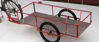
The master shows how, using a hand-made homemade edge bender, it is possible to make an even connection between two parts during auto repair. One of the parts has a uniform, flat surface. 2 parts have an edge with a recess. Millimeter deep groove. Two elements are applied to each other. A weld is made along the groove at the junction. Next it is sanded and leveled. We get an even, neat and flat connection of two elements; after coating with paint, it looks like one whole. The effect of butt welding, but in reality there is an overlap.
Let's look at the design of a manual edge bender in more detail. Small vice for stability. Support point. The length of the levers is 0.5 meters. 25 tube. Two pieces of tire are welded to it. Two holes. The result is a U-shaped part. Bolts 12. Let's try to disassemble the tool. When will it be possible to show all the components in more detail. The protrusion on this part is not formative. 2 parts have a counterpart. A lever is made to make work easier.
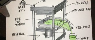
Two levers are connected to each other through a fulcrum. The pipe is 25, the tire is the same size. Shoulder length 100 millimeters. The distance between the bolts is 25 millimeters. The inner tube is 20 x 20. A millimeter plate is welded to it. The plate compensates for the difference in external and internal diameters. To simplify the design, a thread is cut into the cheek. The master did not use any drawings in the process of making this hand-held device; everything was done on a whim. The entire structure was drawn on paper.
If you want to replicate this design for your auto repair shop, then the following video will be valuable to you. Here you can see all the necessary drawings of this tool, which is called an edge bender. A very convenient device for working in the auto repair process.
A manual edge bender for auto repair, made by yourself, is easy to use and is popular among tinsmiths. There are a number of modern offerings of this device available at retail, although it is not difficult to manufacture.
Where is edge bender used?
The device has found application in many areas of industry. In particular, it can be used to form seams in roofing iron, air ducts, and prepare product edges for welded joints. Today, car repair is given one of the first places in the use of the device, since cars are becoming the most popular among the population every year.
How to choose the kinematic diagram of a bending machine
The most accessible machines for making with your own hands are machines in which sheet metal will bend as a result of turning a movable crosshead. The operating principle of such a machine is as follows.
The workpiece to be bent is installed on the guide plane of the lower table of the machine and fixed by a stop, which is fixed to the support frame of the device (it is advisable to provide for adjustment of the stop).
In the guides of the sheet bending frame, the upper traverse moves back and forth, which, when moving downwards, clamps the bent product with its ruler.
In front of the lower table there is a rotating beam that can rotate around its axis. The rotation can be done with a handle from a lever drive, but a version with a foot drive can be made. In the latter case, the operator’s hands remain free, which makes it easier to manipulate the workpiece when it is pressed against the ruler of the upper traverse. In addition, when operating a sheet bending machine using a foot, your hands get less tired.
The set of bending tools on the top and rotary beams may vary. The easiest way for this purpose is to order a set of punches and dies with the required bending radii and standard seats. You will have to send all the details with your order - ruler, clamp, etc. – which will require qualified milling work for their production.
The bevel of the top beam will determine the largest value of the bending angle by which the sheet metal can change its axis.
To make such a unit with your own hands, you will need the following materials:
- steel channel number 6 and above;
- a set of steel angles intended for making your own machine support frame;
- thick-sheet broadband steel from which the rotary, upper and lower beams will be made;
- assorted fasteners;
- rod for the manufacture of a manual lever drive for turning a beam.
To make work easier, you can also use a bench vice, guides from a decommissioned lathe, as well as massive hinges from steel entrance doors.
Using a similar principle, you can make a homemade sheet bender using wooden parts. True, it will only be able to bend aluminum and thin-sheet steel (up to 1 mm in thickness), but in many cases these capabilities are quite sufficient, and the labor intensity of building a sheet bending machine with your own hands will be noticeably reduced. In particular, there is no need for welding operations. It should be noted that the working parts of such a machine should be made only from hardwood (pine, spruce are not suitable).
Having decided on the operating principle of the sheet bender, you can look for suitable drawings. However, a person with an engineering education will be able to produce a set of drawings independently. The advantage of this option is that a number of working drawings can be quickly modified and processed to suit specific capabilities and source materials.
Drawings of the sheet bender must take into account the method of installation. For small units, for example, the bending machine can be mobile or even portable. Otherwise, you will have to use welding to make a stable base, otherwise excessive mobility of the machine will reduce the accuracy of work on it.
Once the machine is ready, it must be checked for functionality and accuracy. To do this, bend a test strip of thick cardboard of the required thickness. If the bending is performed correctly, then the height of the strip flanges will be the same, and there will be no traces left on its surface from the deforming tool.
If you find an error, please select a piece of text and press Ctrl+Enter.
Equipment design and manufacturing
To make an edge bending machine yourself, and thereby facilitate the work of a tinsmith, you do not need to have practical experience. The main elements that ensure metal bending are:
- supporting surface;
- working base;
- clamping force;
- punch compression;
- levers, in the form of handles.
When developing drawings, if necessary, an additional hole punch can be made in the same device. Modern models of machine equipment use a knife to trim edges. It's also easy to make.
- The supporting surface or base of the device - this can be a table made of a pipe or metal profile, a wooden table on powerful supports, if there is a need to bend roofing iron 0.8 mm thick. A manual edge bender is designed for this value. There is no need to make special efforts, because the base is affected by insignificant forces. But the base must be strong enough, this is necessary for the accuracy of bending the metal sheet.
- Working base or table - the average dimensions of the working surface are 1m x 1.5m, more is possible. When working with sheets of overall dimensions, such characteristics will not be superfluous, since unforeseen situations may occur. For fastening to the base, it is preferable to use No. 8 or 6.5 channel. Fasteners should be made clearly horizontally. It is possible to use welding of metal structures. When using wood for the base, bolted fasteners will be the most reliable.
- Clamping - a clamping rod is used to ensure metal clamping when bending edges. You can make it using one of the options. For example, a corner with a shelf of 0.05 m, or the same rental is installed below on a larger edge. This ensures pressure to the punch at a given angle of 1350. Such sheet benders can easily bend the metal at a right angle. Holes for bolts are drilled on both sides of the clamping mechanism. Clamping can also be carried out using wings with welded pins to the base of the structure. Springs can be used to install more complex clamps. To imagine how a spring works, just watch a video on the Internet.
- Making a punch - the drawings of this element provide for the use of a square profile pipe or an angle with thick-walled shelves of the same size with a clamping device. The design involves rotation around an axis horizontally, while the upper front edge must necessarily coincide with the punch. Loops are welded at the ends for these purposes. In this case, it is important to position the clamp exactly vertically. This is the only way to prevent distortions from occurring when bending metal. It is necessary to ensure that the punch is adjacent to the edge of the working base without gaps, so the bend line will be more accurate. If the condition is not working, then the face of the punch, located on top, is in the same plane with the surface of the table. There should not even be a deviation of 1 mm. If, nevertheless, deviations occur, then the work of the machine tool will still be carried out, but the bending radius will be larger, and the result will be a rounding in place of a straight line. A hole punch can be made as an additional option for the device.
- Drive - a half-meter lever is welded to the front of the punch or to the side. For ease of work, it can be made in the form of a bracket. But for practical work, it is best to use a telescopic type lever. Its length can be easily adjusted if necessary. It is easy to make such a device from two pieces of pipe. The length of the lever itself must be firmly fixed for the given positions. For this, pins are used that connect the holes through each other in increments of 0.1 m. This step will be the most optimal, since the applied force is felt when it is adjusted by 10 cm. The design of such a handle regulates the effect of forces on metals of different thicknesses. To bend edges up to 0.8 mm, material made of galvanized or ferrous metals with a thickness of 3 mm or more is used, for example, for body work, a telescopic design will make it possible to increase the force by 2 times or more. Damage to the ribs is excluded, since the load is evenly distributed during operation. The type and thickness of the metal being processed depends on the mechanical force on the drive. When using clamping bars with different profile edges, it is possible to bend complex edges. You can also provide a pressing force and make a stiffening rib on one of the cuts or along the perimeter of the sheet.
We make a manual edge bender with our own hands. Drawings and videos
Beading edges in sheet parts of a car during its repair is not an energy-intensive operation, so even with significant volumes of work, it is advisable to acquire a manual edge bender rather than a powered one.
The technological advantage of this process is that the workpiece can be left under pressure as long as required to overcome the elastic inertia of the material.
Manual edge benders usually form the edges of sheet metal with a thickness of up to 0.8...1.0 mm, with a side height of up to 20 mm.
Device of manual edge benders
Edge benders, although somewhat similar in appearance to sheet benders, have a fundamental difference - the height of the shelf usually does not exceed 5...20% of their length. A lower value corresponds to flanging the inner edge. When bending there is no such limitation, which predetermines noticeable design changes in the compared devices.
The first of them concerns the length of the flanging working area - for manual edge benders it can be small, since the height of the bead and the radius of curvature do not change. Accordingly, portable manual edge benders are produced, moving which along a pre-marked flanging line, we obtain the required profile.
If the edge formation zone is large, the process should be performed simultaneously. In such cases, an edge bender is more similar to a sheet bender, differing, in fact, only in the way the workpiece is pressed.
Let's consider the first version of the device. Portable manual edge bender for gradual bead shaping includes:
- Two handles, and one of them or both can be movable.
- Lever reinforcement system to create the required flanging force.
- Working jaws with a profile that matches the dimensions of the edge. Typically, the manufacturer equips a manual edge bender with a set of several jaws and the most commonly found in practice edge height and radius of curvature during the transition from the edge to the main plane.
- Adjustable travel stop: most often this is a removable slotted screw equipped with a thrust thread.
For ease of use, the handles are rubberized, which prevents the operator’s hand from slipping while applying force.
The second version of a portable manual edge bender is a roller bender, where the sliding friction of the jaws on the workpiece is replaced by rolling friction when the working rollers rotate.
In this case, the shaping force is significantly reduced, but the tool turns out to be less universal, since there is only one pair of rollers, and it is not possible to change the edge formation parameters except by replacing a pair of rollers, which is quite labor-intensive.
In addition, roller edge benders in most cases fail to perform internal flanging along small radii.
The main disadvantage of manual portable edge benders is their low accuracy: when moving the tool along the uneven line of the future edge, an error gradually accumulates, which at the end of the operation can reach a millimeter or more. This is unacceptable during auto body repair, so the quality of bead formation is determined only by the experience of the performer.
Do-it-yourself manual edge bender
Let us dwell on the option of designing and manufacturing a manual edge bender with simultaneous production of an internal or external contour along the entire length of a pre-marked workpiece.
The general view of the device is shown in the figure.
Such a manual edge bender can be used not only in car repair shops, but also in roofing work, the manufacture of tin ventilation ducts and other spatial products made of sheet metal.
The dimensions of a homemade manual edge bender are determined depending on the largest dimensions of the workpiece for which flanging is performed. For example, for large products, it is more expedient to build a table from wood or multi-layer plywood, on which to mount the edge bender; in other cases, the structure is welded from channels and sheet metal.
The design of the manual edge bender is designed for sequential execution of two transitions:
- clamping the workpiece using a clamp and lower clamp;
- flanging along a given contour by turning the handle with the punch located on it.
It is usually recommended to make a welded version of such an assembly, but this is impractical: the parameters of the flanging curve may change, and it is no longer possible to change the punch. Therefore, taking into account the small forces arising during deformation, it is better to produce a collapsible punch, which is a collection of individual modules, characterized by their radius of curvature and edge height.
The fastening of such punches to the beam is carried out using bolts (of course, all seats must be designed and made with the highest possible accuracy).
The edge formation itself is performed after the workpiece is securely fixed between the upper and lower clamps (the latter ensures smooth clamping due to the spring mounted on the rod in the upper plane). The combination of the two halves of the flanging die is carried out by moving the support bracket along the mating surface of the stops, which act as guide elements of the manual edge bender.
By changing the configuration of the punch modules, you can perform flanging not only at a straight line, but also at any other angle - up to 110...120º (to do this, you just need to provide a small bevel on the limiter, which is visible in the figure).
About other equipment for bending metal edges
A homemade edge bender for body repair can also be pneumatically driven. Pneumatic edge benders are in demand among tinsmiths. The principle of operation is to create a pressure of up to 6.2 bar, due to pneumatic cylinders and beam rotation. It can be used with metal thicknesses up to 1.2 mm, and the resulting edge width can be up to 12 mm. Air consumption 113 l/min.
Automatic edge benders can be purchased at retail. The price is reasonable and the device is simple. It is not necessary to have experience when using equipment in repairs. The hole punch-edge bender is popular because it can be used to simultaneously bend the edge of a metal and make a hole with precision.
Such a simple tool as an edge bender can be useful in many situations involving the need to process sheet metal products. There are many models of such a device on the modern market, but if you wish, you can make it yourself.
Edge benders can be used to form quite complex profile elements
Drawing up technical specifications
Thanks to the capabilities of the Internet, you can quickly find the required set of drawings, and on the YouTube channel you can even watch advertising and informational videos about the device and operating principle of the required unit. However, all these materials are strictly individual, and therefore were intended by their authors for specific sheet-bending operations. Therefore, before building a sheet bending machine with your own hands, you need to make the right choice of its future technical characteristics. The main ones should be the following:
- maximum width of bent metal, mm;
- maximum thickness of the workpiece, mm;
- desired range of bending angles;
- overall dimensions of the mechanism (length, width, height);
- required bending accuracy.
The direct choice of the limit values of the listed parameters depends on the conditions of use of the machine that will bend sheet metal products. In particular, when constructing a roof, you will most likely have to deal with galvanized sheet or steel with a thickness of no more than 1 mm. When processing copper, an even thinner sheet or strip is often used, and when making fences and railings with your own hands, on the contrary, the thickness of the metal can be 2 - 3 mm.
When choosing the optimal width of a workpiece - sheet or strip - you should proceed from the fact that the width of the part will rarely exceed 1000 mm (in extreme cases, adjacent workpieces can then be joined into a fold using the same machine).
Drawing of a homemade sheet bending machine
The most difficult point in the technical specifications is considered to be the choice of the optimal range of metal bending angles. If everything is clear with the upper limit - 180°, then the lower value should be chosen very wisely. A natural consequence of bending most sheet metals in a cold state is springback - a spontaneous decrease in the actual bending angle due to the elastic properties of the deformed metal. Springing depends on:
- Plasticity of the material: for example, for low-carbon steel the maximum spring angle is 5 - 7°, and for high-carbon steel - up to 10 - 12°. Alloy steels and alloys are even more springy. In particular, for aluminum alloy AMg6, the maximum springback can be 12 - 15°;
- Thickness of the bent part: with decreasing metal thickness, springing decreases;
- Bending angle: as this angle decreases, the springback of almost all metals increases. In particular, at relatively small bending angles (up to 15 - 20°), it is generally impossible to bend a workpiece made of most types of sheet metals and alloys to a given amount in the usual way: it is necessary to use units with simultaneous longitudinal stretching of the sheet. It is impossible to make such machines with your own hands: you will need to install and debug a special hydraulic drive. Therefore, in such cases, it is easier to bend the part with the usual blows of a mallet on, for example, a wooden matrix.
Areas of application
An edge bending machine or a simple hand tool designed for bending edges is widely used in many areas. The edge bender makes it possible, in particular, to produce air duct elements from thin sheet metal and to prepare the edges of workpieces for joining them by welding. Auto repair (body work) is another area of application for such tools and equipment.
Edge bending is also actively used in construction and when performing home repair work. Using such a tool, seam joints of thin-sheet metal elements are formed and even products of various configurations are manufactured.
Bending the end of a drainpipe on an electromechanical edge bending machine
How the machine works
The main parts of a metal bending machine are:
- base;
- Desktop;
- clamp;
- crimping punch;
- handles - levers.
The base of the machine can be a welded metal table made from a corner or a profile pipe. When installing equipment permanently, you can also use a durable wooden table with massive legs. When bending sheet metal up to 0.8 mm thick (namely, these are the thicknesses that a homemade edge bender is designed for), no special effort is required, so forces of limited magnitude act on the base (frame). The strength of the base is required only for bending accuracy so that distortions do not occur.
The table dimensions are at least 1.5 m in length and up to 1 m in width. Even if you don't plan to work with large sheets of metal, it never hurts to have some extra. Sometimes non-standard situations arise for which every master should be prepared.
A work table is fixed to the front edge of the base - a section of channel No. 6.5 or No. 8. It must be positioned strictly horizontally and securely fastened to the base. If it is metal, then it is best to weld it. It can be attached to wood with bolts with a diameter of 10 mm.
Clamp
A pressure bar is installed on the top of the work table, which also serves as a supporting surface. You can do it in several ways. It is best to use a corner 5X5 cm or larger, installed edge up. In this case, the front edge facing the crimping punch will be inclined at an angle of 135. This will allow you to easily bend the metal sheet at an angle of 90 degrees or more.
Holes for bolt fastenings are drilled on both sides of the clamp. You can weld studs to the base and press the rail with the wings, or you can install more complex clamps with return springs, which, after releasing the wings or rotating the handles, automatically raise the clamp. You can see how this system works in the video.
Punch
The front working punch is made of a square pipe or thick-walled angle with the same size as the clamping device. It should rotate around a horizontal axis coinciding with the top front edge of the punch. To do this, loops are welded at its ends
It is important to accurately level the clamp so that distortions do not occur during bending. The clamp should fit as tightly as possible to the edge of the desktop, with a minimum gap. The smaller the gap, the more accurate the fold line will be
The smaller the gap, the more accurate the fold line will be.
When not in use, the top edge of the punch is flush with the table surface. There shouldn't even be a millimeter difference. If there is a deviation in level, then a machine made by yourself will also work, but the bending radius will increase and instead of a straight line you will get a rounding.
Main varieties
The simplest design of the edge bending devices on the market are manual roller type devices. All manipulations with such edge benders are carried out using the handle with which they are equipped, and the main work of deforming the edge of the metal workpiece is performed by the rollers. The width of the bend performed using such a device is regulated by means of a special limiter installed on the guides of the device.
Compact manual edge benders can be used directly on site
High mobility of the edge bender, which can be used even on high-rise objects, is ensured not only by its compact dimensions, but also by its low weight, about 2 kg. Using a hand-held edge bending tool, you can bend the edge of a metal workpiece at an angle of up to 90°, while the thickness of the metal from which it is made cannot exceed 0.8 mm.
Using an edge bender, you can make bends of any length, and their width can be in the range of 0.5–20 cm. As can be seen from the technical characteristics of such a device, its capabilities are quite limited, so it is advisable to use it only for solving simple technological problems. An edge bending machine equipped with a hydraulic drive is more productive and functional. The operator working on such equipment does not need to exert significant physical effort in order to bend the edge of a metal workpiece. Due to the high power that this device is distinguished by, it can be used for processing sheet metal workpieces even of considerable thickness.
Edge bending machine ZSH-4.0 with hydraulic roller clamping
Depending on the dimensions, a hydraulic edge bending machine can be stationary or mobile. It is the hydraulic drive that is most often equipped with such equipment, which also has another name - “edge bending press”.
The edge bending machine can also be equipped with an electromechanical drive. Using this equipment, you can make folds of various types and even perform upsetting of the folded seam, if the equipment of the machine allows this to be done.
Manual edge bender for do-it-yourself auto repair
Butt welding is notoriously difficult to do on thin iron material. Thanks to the tool, which is presented in this video of the “autoreanimator” channel, the work of auto repair is greatly facilitated.
Now you can mask a seam that is overlapped, resulting in a complete illusion of butt welding. Externally it looks very impressive and beautiful. First, look at how the master works with this tool of his, the design of the edge bender.
In the second video you can see product drawings.
The master shows how, using a hand-made homemade edge bender, it is possible to make an even connection between two parts during auto repair. One of the parts has a uniform, flat surface. 2 parts have an edge with a recess. Millimeter deep groove.
Two elements are applied to each other. A weld is made along the groove at the junction. Next it is sanded and leveled. We get an even, neat and flat connection of two elements; after coating with paint, it looks like one whole.
The effect of butt welding, but in reality there is an overlap.
Let's look at the design of a manual edge bender in more detail. Small vice for stability. Support point. The length of the levers is 0.5 meters. 25 tube. Two pieces of tire are welded to it. Two holes.
The result is a U-shaped part. Bolts 12. Let's try to disassemble the tool. When will it be possible to show all the components in more detail. The protrusion on this part is not formative. 2 parts have a counterpart.
A lever is made to make work easier.
Edge bender drawing
Two levers are connected to each other through a fulcrum. The pipe is 25, the tire is the same size. Shoulder length 100 millimeters. The distance between the bolts is 25 millimeters. The inner tube is 20 x 20. A millimeter plate is welded to it.
The plate compensates for the difference in external and internal diameters. To simplify the design, a thread is cut into the cheek. The master did not use any drawings in the process of making this hand-held device; everything was done on a whim.
The entire structure was drawn on paper.
If you want to replicate this design for your auto repair shop, then the following video will be valuable to you. Here you can see all the necessary drawings of this tool, which is called an edge bender. A very convenient device for working in the auto repair process.
izobreteniya.net
Self-production of an edge bending machine
How to make a device for performing edge bending operations? This problem can be solved quite simply.
Option one. Long straight edge bending machine
In order to make such a device, you will need its drawings, which are easy to find on the Internet, as well as the following equipment and consumables:
- metal channels from which the base and clamps of the edge bender are made;
- thick-walled corner for making a crimping punch;
- metal sheet from which the edge bender brushes will be made;
- a metal bracket used as a handle for a device.
Scheme of operation of a homemade edge bender
The assembly diagram for making a machine for performing edge bending operations is as follows:
- The edges of the punch and base are chamfered, the size of which should be 7×45°, and the length should be 30 cm.
- Metal rods with a diameter of 10 mm are welded to the punch, which will act as axes. When welding such rods, it is necessary to ensure that their axis coincides with the edge of the angle.
- Samples are made at the ends of the working part of the clamp.
- A homemade edge bender is pre-assembled in a vice, with the help of which the punch is compressed with the base. In this case, it is important to ensure that the wall of the punch and the working shelf of the base, between which the cardboard spacer is placed, are located in the same plane.
- Steel brushes are placed on the punch axis and pressed to the base using clamps.
- After checking the correct position of the brushes, they are welded to the base of the device.
- Holes are drilled at the base of the edge bender into which clamping bolts are screwed.
- Studs are welded to the base of the machine - a metal channel - onto which nuts are screwed.
- Having unscrewed the bolts, they are inserted into the drilled holes of the clamping mechanism and the restriction nuts are screwed onto them.
- A handle is welded to the metal corner of a homemade edge bender.
Drawing of a bending beam (click to enlarge)
Drawing of the lower beam (click to enlarge)
Drawing of the pressure beam (click to enlarge)
Once your edge bending device is assembled, all that remains is to secure it in a bench vise.
Edge bender mounted on a workbench
A video review of the manufacture of the first version of the edge bending machine can be seen in detail in the video below.
Option two. Manual edge bender for flanging
With this homemade device you can bend edges of any length, and the design is taken from manual factory-made edge benders.
The entire work progress of this type of edge bender is shown in detail in the video below.
Using these examples, we examined the procedure for manufacturing standard edge benders, which can be used to perform a whole list of technological operations. If you need an edge-bending device, which is used to carry out auto repairs, then it has an even simpler design and, accordingly, low cost, so it is not practical to make it yourself: it is better to purchase such a device.
And finally, another option for making a homemade edge bender in video format.
Manual edge bender for do-it-yourself auto repair. Drawings and videos
Beading edges in sheet parts of a car during its repair is not an energy-intensive operation, so even with significant volumes of work, it is advisable to acquire a manual edge bender rather than a powered one.
The technological advantage of this process is that the workpiece can be left under pressure as long as required to overcome the elastic inertia of the material.
Manual edge benders usually form the edges of sheet metal with a thickness of up to 0.8...1.0 mm, with a side height of up to 20 mm.
A little about the design of a homemade sheet bender
The simplest design is to clamp the edge of the sheet between a steel corner and a rule (or two corners) using a clamp, and bend the workpiece by hand. This is how the simplest roofing elements are usually created.
IMPORTANT! All work with metal must be performed using protective gloves.
However, it is quite possible to make a traverse sheet bending machine yourself. Precision markings and patience are required.
The design and operating principle are visible in the drawings.
Do-it-yourself bracket bender is not inferior to the factory one
I needed a bracket bender for work. A factory tool for bending gutter holders costs about 5,000 rubles. I looked at pictures on the Internet and repeated the design.
The device of the bracket bender is clearly understood from the photo below.
Tool at work.
According to the user, he bent many gutter hooks using a homemade bracket bender, and the homemade product showed only its best side.
Step-by-step manufacturing instructions
To make a traverse sheet bender we will need:
- 4 meters of steel angle, side – 50 mm;
- Ball joint for car, with mounting bracket;
- The stabilizer rod is from the same, with a diameter of 10 mm;
- Grinder, drill, electric welding.
- We cut the rolled metal into pieces of 1 meter with a grinder. If there is a need to work with metal of a larger width, the length of the corners increases. At least 100 mm must be added to the width of the working surface.
- Using an angle grinder, we cut out two eyes from the ball joint bracket. These will be the working loops of the movable traverse.
- From the stabilizer strut we make an axis on which the hinges will rest. IMPORTANT! The future play of the rotary mechanism depends on the quality of fit of these elements.
- We carefully measure and mark a sample on the corner for attaching the axle.
- We grind the flats strictly to size to install the axle shafts. This must be done as accurately as possible so as not to waste time and material on subsequent adjustments.
- We apply the markings exactly in the center of the axis, and combine it with the top of the corner - the traverse. This point is important. because if the alignment is incorrect, the quality of the workpiece bending on the machine will deteriorate, or the sheet bender will be unsuitable for work.
- We weld the axle shafts to the samples, maintaining parallelism to the top of the angle. To increase accuracy, you should use a jig when welding. For example, a vice and a clamp. The length of the protruding part of the axis does not exceed 1 cm.
- The result should be a structure with perfect alignment at the ends.
- Place the corners next to each other.
- We mark the sample on the second corner strictly opposite the axes of the first corner.
- The angles relative to each other should be located as follows:
- We fold both traverses, keeping them flat, and fix them for welding. We weld the loops onto the second corner on both sides.
- The corners should rotate freely relative to each other on their hinges. When turning 180 degrees there should be no snags or wedging. In this case, the gap between the traverses should be minimal.
- The metal clamp will be positioned as follows:
- Having previously marked, we use a grinder to cut out a sample around the axis on the clamping angle. The lower side of the clamping angle is ground at an angle of 45 degrees. IMPORTANT! The edge should remain perfectly straight; it is along it that the fold line will run. In case of unevenness, creases and folds on the workpiece are possible.
- Opposite the axes, mark and drill holes for 10 mm bolts. We weld the bolts with the threads up to the lower fixed cross-beam.
- We also make a hole in the center of the traverse, but do not weld the bolt. This will be a removable element, so we weld the short axle to it in a T-shape.
- Bolts are needed to press the workpiece to the crossbeam when bending. The central bolt is used when the workpiece has a width that is half that of the traverse. When working with wide workpieces, the bolt is removed.
- From a 15-20 mm circle we cut two handles 30 cm long. A thinner rod will not work, since the force on the handles can be significant, and you can simply bend them.
- We weld the handles from the bottom of the turning angle (traverse).
Popular: Die for cutting threads on pipes: how is it different from a die?
Making a bed for a sheet bender
We weld the fourth corner to the lower fixed cross-beam on both sides for strength. We drill holes in the frame. The entire structure must be fixed on a stable surface, for example, on a steel workbench.
We screw the sheet bender to the workbench and check the free movement of the movable traverse.
The design allows you to work with iron sheets up to 2 mm thick and 92 cm wide. Bend angles can be selected to any size; the workpiece can be bent either in one direction or in steps.
When working with a thick workpiece, the handle is extended with a metal pipe; the strength of the angle is always sufficient. Working with standard galvanized sheeting is not difficult; the device bends it with the ease of cardboard.
Temporary structure according to a simplified scheme
The considered version of the sheet bender is made for regular work, and is actually a stationary device. If you urgently need to do one-time work on making tin products, you can create a simpler device.
For production you will need:
- Three corners 40-50 mm, width according to your needs;
- A pair of door hinges;
- Two powerful clamps;
- Two rods (circles) as handles.
The two corners are fastened together with loops as tightly as possible.
The third, shorter corner, using clamps, presses the workpiece and the lower crossbeam to the workbench. This machine is not very convenient, but this is compensated by its ease of manufacture. The manufacturing option is up to you to choose.
A simple solution for sheet bending
This homemade sheet bender can be made in 30-60 minutes.
Minimum amount of materials required:
- Corner No. 5 1.5 meters long.
- Channel No. 18 - 20, as a bed. Length 1.5 - 2m.
- Water pipe 2-3 m, for making a handle
- two door hinges, preferably garage ones.
How to assemble the structure can be seen from the attached photographs. The machine is simple but effective, unless, of course, you require special precision for bending sheets.
Pay attention to the dimensions of the sheets you are going to bend. It is necessary to weld the hinges with a reserve. Add 20-30 cm to the width of the sheet so that the sheet fits freely between the loops, make markings and safely weld.
What types of benders are there?
Of course, you can buy a ready-made bender, for example, the famous Edelweiss, but such machines also cost a lot, but if you make them yourself, you won’t need any special financial costs. There are several types of metal bending machines :
- Manual bending machines. Metal bending occurs through the application of physical force. Despite the apparent simplicity of the design, they can be used to perform almost all necessary operations with sheet metal, including folding work.
- Hydraulic sheet benders. Very similar to manual machines, but the application of force occurs due to a hydraulic drive.
- Roller edge bending machines. They differ from the previous ones not only in design, but also in the principle of operation. In them, the sheet does not bend along a certain line, but is smoothly rounded. Such machines are necessary for the manufacture of pipes and other similar products.
Manual and hydraulic machines are easier to manufacture than roller machines. Do-it-yourself edge bender drawings are easy to find, but the process of their production itself is not described everywhere.
Tools and materials
A manual edge bender is an ideal assistant for those who like to tinker with sheet metal and tin . But to start making a homemade tool, you will need to study its design in more detail.
The manual machine has:
There are several options for materials and initial tools from which an edge bender could be made. For example, it is quite easy to remake it from pliers.
But it is also important that the machine not only creates edges with ease, but also allows this work to be done with good quality.
To create a manual machine according to one of the drawings you will need to have on hand:
- channel No. 5, used to create the base;
- channel No. 6.5, from which the clamp is made;
- thick-walled corner;
- crimp type punch No. 5;
- steel sheet 5 mm thick for making brushes;
- for the handle – a bracket with a diameter of 15 mm.
The following parts are required for the flange bender:
- clamp;
- limiter;
- spring-loaded clamp;
- support bracket;
- top clamp;
- punch;
- rotary axis for the handle.