A generator that produces electrical energy through rotation (mechanical energy) is called a dynamo. Due to its properties, the direct current generated by it is not used in everyday life as often as alternating current. All power plants are equipped with giant alternating current generators (alternators). Despite this, the dynamo remains a relevant device that serves well in some electrical fields, for example, when charging batteries. Therefore, a small generator assembled with your own hands will always find a use.
Who invented the dynamo and how does it work?
In 1831, the English physicist Faraday discovered an unusual electromagnetic phenomenon. An electromagnetic field arose in the copper wire during rotation between the magnetic poles. It was this that excited the movement of electrons along the conductor. Based on research, the physicist formulated the law of electromagnetic induction. The conductor was a copper wire wound onto a metal rod with a magnetic property. When the magnetic particles in the rod aligned with the poles, it turned into a magnet and attracted metal objects to itself. To magnetize the rod, you can use a coil or a permanent magnet. The effect occurs when one electromagnet rotates strongly around another.
In the same year, a device for converting electrical energy into mechanical energy appeared. The first electric motors resembled steam engines: only electromagnets were installed instead of cylinders, and metal armatures were installed instead of pistons.
In 1834, Russian academician Boris Jacobi created the first electric motor with a rotating armature. Four years later, the academician used an improved electric motor on the world's first motor boat. The world's first alternating current generator was built by Pavel Yablochkov. And the invention of another Russian scientist M. Dolivo-Dovolsky - a three-phase current generator - was truly revolutionary.
Operating principle of an electric current generator
A dynamo generates electrical energy through the principle of electromagnetic induction. Typically, such a device converts mechanical influences directly into electrical impulses. It consists of a rotor (an open wire winding) and a stator in which the poles of the magnet are located. The rotor, without stopping its movement, rotates all the time in a force magnetic field, which inevitably leads to the generation of current in the winding. The dynamo represents the following diagram of its device. A rotating conductor, or rotor, crosses a magnetic field and a current is generated in it. The ends of the rotor are connected to the ring (collector), through them and the pressure brushes the current moves into the electrical network.
DIY dynamo, its elements
In order to build a dynamo, you will need such basic elements as a housing, a rotating armature, a commutator, a brush holder, brushes, and insulated copper wire.
Let's consider the preparation of each element separately.
| Dynamo device | |
| There are different options for making the case. A tin can or a piece of pipe (diameter 100 mm) is suitable for it. First, you need to cut out the bottom of the can and weight the body. To do this, wrap a strip of iron of the same width very tightly in several rows on the inside or outside of the can. Then we rivet or solder the strip to the body. Secondly, we make cores for electromagnets and shoes for them from tin or iron. We take strips of tin along the width of the body, bend them, place them on top of each other, fasten them with iron wire and solder them along the sides. We attach the cores to the holes in the housing located opposite each other. Using screws, screw the body to the block (wooden or metal). In the housing we make two bearing strips (brass or thick sheet metal, size 110x20 mm) and a stand (80x20 mm) to secure the armature. We solder the strips in a cross pattern and make a hole in the center along the diameter of the axis. The same hole in the rack 10 mm from the end. Copper tubes (10-15 mm with a diameter of 8 mm) can be soldered into the bearing holes. We solder the first bearing to the body with the ends of the strips, after which the system will bend outward. |
| The anchor must be made carefully, since it largely determines how the dynamo will work. You can assemble an anchor from tin plates. The thickness of all plates must be equal to the thickness of the body (50 mm); their manufacture requires special precision. Approximately 120 circles (46 mm in diameter) will have to be cut out of iron. We divide each circle into eight sectors using a compass, make markings through the center of the circle, and in the center of the circles we draw two circles with a diameter of 8 and 38 mm. At the intersection of the large circle with the sector lines, we draw another 8 mm circles. On all round plates, where the circles are drawn, we accurately drill eight 8 mm holes. We tightly fasten the plates with nuts and put them on the axle, you should get an anchor with round longitudinal grooves. We round off sharp corners in the grooves with a file. |
Story[
Jedlik Dynamo[
In 1827, Hungarian physicist Anjos Istvan Jedlik began experimenting with electromagnetic rotating devices, which he called electromagnetic self-rotating rotors. In the prototype of his unipolar electric motor (completed between 1853 and 1856), both the stationary and rotating parts were electromagnetic. He formulated the concept of a dynamo at least 6 years before Siemens and Wheatstone, but did not patent the invention because he thought he was not the first to do so. The essence of his idea was to use, instead of permanent magnets, two oppositely located electromagnets, which created a magnetic field around the rotor. Jedlik's invention was decades ahead of his time.
Faraday disk[
Faraday's Disc In 1831, Michael Faraday discovered the principle of operation of electromagnetic generators. The principle, later called Faraday's law, was that a potential difference was formed between the ends of a conductor that moved perpendicular to a magnetic field. He also built the first electromagnetic generator, called a Faraday disk, which was a unipolar generator using a copper disk rotating between the poles of a horseshoe magnet. It produced a small constant voltage and a high current.
The design was imperfect because the current self-closed through areas of the disk that were not in the magnetic field. The stray current limited the power drawn from the contact wires and caused unnecessary heating of the copper disk. Later, homopolar generators solved this problem by placing many small magnets around the disk, distributed around the entire perimeter of the disk to create a uniform field and current in only one direction.
Another disadvantage was that the output voltage was very small because only one turn around the magnetic flux was formed. Experiments showed that by using many turns of wire in a coil, the higher voltage often required could be obtained. Wire windings became the main characteristic feature of all subsequent generator developments.
However, recent advances (rare earth magnets) have made unipolar motors with a magnet on the rotor possible, and should bring many improvements to older designs.
Dynamo machine[
Dynamos are no longer used to generate electricity due to their size and the complexity of the switches. This large belt-drive, high-current dynamo produced 310 amperes of current and 7 volts or 2,170 watts when spinning at 1,400 rpm. Main article: Dynamo
The dynamo was the first electrical generator capable of generating power for industry. Its operation is based on the laws of electromagnetism to convert mechanical energy into pulsating direct current. Direct current was generated through the use of a mechanical commutator. The first dynamo was built by Hippolyte Pixie in 1832.
Having gone through a series of less significant discoveries, the dynamo became the prototype from which further inventions emerged, such as the direct current motor, alternating current generator, synchronous motor, and rotary converter.
A dynamo consists of a stator, which creates a constant magnetic field, and a set of windings that rotate in this field. On small machines, a constant magnetic field could be created using permanent magnets; on large machines, a constant magnetic field is created by one or more electromagnets, the windings of which are usually called field windings.
Large, powerful dynamos are rarely seen today, due to the greater versatility of using alternating current in power networks and electronic solid-state DC-to-AC converters. However, before alternating current was discovered, huge dynamos producing direct current were the only way to generate electricity. Dynamos are now a rarity.
Reversibility of electric machines
The Russian scientist E. H. Lenz pointed out the reversibility of electric machines back in 1833: the same machine can work as an electric motor if it is powered with current, and can serve as a generator of electric current if its rotor is set in rotation by some motor, for example steam engine. In 1838, Lenz, one of the members of the commission to test the action of the Jacobi electric motor, experimentally proved the reversibility of the electric machine.
The first electric current generator, based on the phenomenon of electromagnetic induction, was built in 1832 by Parisian technicians the Pixin brothers. This generator was difficult to use, since it was necessary to rotate a heavy permanent magnet so that an alternating electric current would arise in two wire coils fixed motionless near its poles. The generator was equipped with a device for rectifying the current. In an effort to increase the power of electric machines, inventors increased the number of magnets and coils. One such machine, built in 1843, was the Emil Stehrer generator. This machine had three strong moving magnets and six coils that rotated by hand around a vertical axis. Thus, at the first stage of the development of electromagnetic current generators (before 1851), permanent magnets were used to produce a magnetic field. At the second stage (1851-1867), generators were created in which permanent magnets were replaced with electromagnets to increase power. Their winding was powered by current from an independent small current generator with permanent magnets. A similar machine was created by the Englishman Henry Wilde in 1863.
During the operation of this machine, it turned out that generators, while supplying electricity to the consumer, can simultaneously supply current to their own magnets. It turned out that the cores of electromagnets retain residual magnetism after turning off the current. Thanks to this, the self-excited generator produces current even when it is started from a state of rest. In 1866-1867, a number of inventors received patents for self-excited machines.
In 1870, the Belgian Zenob Gramm, working in France, created a generator that was widely used in industry. In his dynamo, he used the principle of self-excitation and improved the ring armature, invented back in 1860 by A. Pacinotti.
In one of Gram's first machines, a ring armature mounted on a horizontal shaft rotated between the pole pieces of two electromagnets. The armature was driven into rotation through a drive pulley, the windings of the electromagnets were connected in series with the armature winding. The Gram generator provided a direct current, which was discharged using metal brushes sliding along the surface of the commutator. At the Vienna International Exhibition in 1873, two identical Gram machines were demonstrated, connected by wires 1 kilometer long. One of the machines was driven by an internal combustion engine and served as a generator of electrical energy. The second machine received electrical energy through wires from the first and, working like an engine, drove the pump. It was a spectacular demonstration of the reversibility of electrical machines, discovered by Lenz, and a demonstration of the principle of energy transfer over distance.
Before the connection between electricity and magnetism was discovered, electrostatic generators were used, which operated based on the principles of electrostatics. They could produce high voltage, but had little current. Their work was based on the use of electrified belts, plates and disks to transfer electrical charges from one electrode to another. Charges were generated using one of two principles:
Due to low efficiency and difficulties in insulating machines that generate high voltages, electrostatic generators were of low power and were never used to generate electricity on an industrial scale. Examples of machines of this kind that have survived to this day are the electrophore machine and the Van de Graaff generator.
Other electrical generators using rotation[
Without a commutator, a dynamo is an example of an alternator. With an electromechanical commutator, the dynamo is a classic DC generator. The alternator must always have a constant rotor speed and be synchronized with other generators in the power distribution network. A DC generator can operate at any rotor frequency within its permissible limits, but produces direct current.
MHD generator[
A magnetohydrodynamic generator directly generates electricity from the energy of a plasma or other similar conducting medium (for example, a liquid electrolyte) moving through a magnetic field without the use of rotating parts. The development of this type of generator began because its output produces high-temperature combustion products that can be used to heat steam in combined cycle power plants and thus increase overall efficiency. The MHD generator is a reversible device, that is, it can also be used as a motor.
Manufacturing of commutator and brush holder
When assembling the dynamo, in particular the commutator and brush holders, attention and accuracy are required.
| The collector can be made of a tube (copper, brass) or assembled from plates. You will need a tube with a diameter of 20-25 mm and a length of 25-30 mm, which is sawn into 4 equal parts. Two two-millimeter holes are drilled into the plates. Then we cut out a cylinder (diameter 20-25 mm, length 25 mm) from fiber or ebonite, dry wood will also do. We make a hole in the center of the cylinder so that it can fit tightly onto the armature axis. We attach the plates to the cylinder using small screws, each time leaving a space of 1-2 mm between them. You can use twisted wire and insulating tape. The screws should not touch the axle, otherwise there will be a short circuit. We fill the gaps between the plates with rosin. | |
| A brush holder with brushes is used to relieve stress in the commutator. The brushes must extend and rotate around the axis of the armature to change the force and angle of pressure on the commutator. The base, 10 mm thick, will be made of fiber, ebonite or paraffin wood. Let's drill three holes in it so that the two outer ones will fit the bolts. We take copper bolts or 35 mm radio contacts. We screw in the bolts securing the brushes with nuts for clamping. The hole in the center should be equal to the diameter of the copper tube that was used for the first bearing in the housing. Opposite the central hole in the end of the block, we drill a through hole and make a thread for the fastening screw. We take a screw (for wood - a screw) with a slot or edges on the head. Make a hole slightly smaller than the diameter of the screw, screw in the screw. First screw it in 2-3 turns, then turn it out, repeating until it fits in three turns freely. Then we process the next pass with the same screw. We make a bearing frame, drill a hole in the upper end of which, insert a piece of copper tube and solder it. Brushes can be made in different ways, from copper, brass plates or carbon brushes. These can be plates 40-50 mm long with a cross-section of 10-15 mm. At the end of the brush we drill an oblong through hole 20 mm long for the bolts. This hole will allow you to change the pressure, bringing the brushes closer to the commutator. We secure the brushes with washers. To ensure that the brushes touch the commutator tightly, we sharpen their ends obliquely. | |
Let's start assembling a charger for USB devices powered by a dynamo.
Step 1: Veroboard.
Cut a section of the Veroboard approximately 17mm x 40mm. The board in the photo below is too long, approximately 65mm in length.
Step 2: Installation of tantalum capacitors.
Solder two miniature tantalum disk capacitors onto the voltage regulator. Make sure that the components do not overheat during soldering and maintain polarity (long leg is positive).
Place the 22 µF capacitor on the right and the 0.47 µF on the left. The negative poles should be in the middle.
Step 3: Prepare capacitor C1.
Install heat shrink tubing onto capacitor C1. Bend the legs (long leg is positive) as shown in the photo below. Try to keep the legs as long as possible to make it easier to fit the capacitor inside the ABS box.
Step 4: Place components on the board.
To correctly place the components on the Veroboard, see the first photo below: the three parallel strips in the middle of the board serve as the main electrical tracks for the components. The stripe on the left corresponds to the positive side in the circuit diagram.
The long leg of capacitor C1 (+) must be placed on the leftmost strip of the three strips. The short leg must be soldered to the middle strip.
The legs of the bridge rectifier should be positioned as follows. The positive legs (labeled) go to the left. Negative legs should go along the middle strip. The wires from the incoming AC current need to be soldered on the outer strips of the board (left and right, as shown in the photo above).
Finally, solder the voltage regulator.
Before you continue assembling the USB charger, check to see if you did everything correctly.
Prepare the wire that goes to the hub dynamo and connect it to the legs of the bridge rectifier. Here polarity does not matter since we are dealing with alternating current. Connect the hub dynamo, spin the wheel and measure the output voltage at the positive and negative terminals of the board.
We should get about 5 V.
If nothing works, check the polarity of capacitors and other components.
Now we can cut off all the excess on the Veroboard and bend capacitor C1 so that it can fit inside the ABS box.
Connect the cooler using a one-way rivet. It is ideal for this purpose as it does not take up additional space (especially in height).
Before connecting the wires, drill a small hole in the box for the cable gland locknut, install it and feed the wires through it.
Next, connect the USB-A or Mini and Micro USB cable directly to the output legs of the voltage regulator. Connect the wires from the hub dynamo to the bridge rectifier.
In order for the board to fit in the container, I had to saw off the corners.
When using the ABS container listed in the list of required components above, you will need to additionally cut two holes in the bottom of the container.
So we have a stylish USB charger powered by a hub dynamo. To ensure water resistance, I sealed the container with polymer resin. Only seal the container after you are sure the charger is working.
Second version of a USB charger with o-rings:
Source
Winding
For the winding we will use copper wire with paper insulation with a cross section of 0.5-0.8 mm. You need to purchase half a kilogram of wire, the thickness of which will affect the voltage and current. For example, when winding with 0.5 mm wire, 25 volts will be generated at a current of 1 ampere, if you take a wire of 0.8 - 8 volts at a current of 3 amperes. Before starting work, divide the wire into two parts. To wind the electromagnet you will need 450 g of 0.5 wire and 60 g for the armature winding. If you bought 0.8 wire, we will set aside 430 g for the electromagnet, and 70 g for the armature.
A cyclist passes an intersection:
Correct 8. Traffic regulation
8.3. Traffic controller signals take precedence over traffic light signals and road sign requirements and are mandatory. Traffic lights, other than flashing yellow ones, take precedence over priority road signs. Drivers and pedestrians must comply with the additional requirements of the traffic controller, even if they contradict traffic lights, road signs and markings.
16. Driving through intersections
16.6. When turning left or turning around when the main traffic light is green, the driver of a non-rail vehicle is obliged to give way to a tram in the same direction, as well as to vehicles moving straight in the opposite direction or turning right. Tram drivers should follow this rule among themselves.
Wrong 8. Traffic control
8.3. Traffic controller signals take precedence over traffic light signals and road sign requirements and are mandatory. Traffic lights, other than flashing yellow ones, take precedence over priority road signs. Drivers and pedestrians must comply with the additional requirements of the traffic controller, even if they contradict traffic lights, road signs and markings.
16. Driving through intersections
16.6. When turning left or turning around when the main traffic light is green, the driver of a non-rail vehicle is obliged to give way to a tram in the same direction, as well as to vehicles moving straight in the opposite direction or turning right. Tram drivers should follow this rule among themselves.
- Task 12 of 15
Dynamo assembly
The dynamo is assembled with your own hands in several stages:
- For the base we will prepare a board measuring 150x200 mm, 30 mm thick. Let's drill two holes from the edges of the electromagnet ring.
- We fasten the housing to the base with two screws so that the electromagnets are located on the same horizontal line opposite each other.
- We place wooden blocks on the sides of the body so that it sits firmly and screw them to the base.
- Then we pass the free end of the armature axis through the bearing on the housing. We insert it into place between the electromagnets.
- We put a brush holder with brushes on the bearing of the bearing frame from the inside and insert the end of the armature axis with the commutator. A thick metal washer or wire ring must first be placed on the collector.
- We install the armature so that when it rotates between the electromagnets, it does not touch them and is at the same distance from them. The stand is attached to the base with two screws.
: Motor Installation
The engine mount was made of an aluminum angle and a reflector bracket. To mount the engine, holes were drilled into the aluminum. One side of the corner was then cut out to make room for the wheel.
The wheel was attached by wrapping duct tape around the motor shaft until the connection was tight enough to push the wheel directly onto the duct tape. This method works well, but it needs to be improved in the future.
Once the motor and wheel were attached to the aluminum, I found a good spot on the frame to mount everything. I attached the blank to the seat tube. My bike's frame is 61cm, so the area where the generator is mounted is quite large compared to smaller bikes. Just find the best place on your bike to mount the alternator.
Once I found a suitable location, I made marks for the aluminum bracket with the reflector bracket installed so it could be cut to size. I then drilled holes in the bracket and aluminum and mounted the structure onto the bike.
Dynamo Adjustment
- We fix the brushes so that they lightly touch the commutator and do not significantly slow down its rotation.
- Let's check that the connections are correct and that there are no breaks or short circuits. We connect a 15-20 volt battery to the mechanism. If the motor is running and the armature rotates quickly, it means that the dynamo was assembled correctly with your own hands.
- After checking, we connect the dynamo to a drive, for example from a foot-operated sewing machine. We connect a 10-volt battery voltage to the brushes to magnetize the electromagnets. After a minute, the battery should turn off, then we begin to quickly rotate the armature using the drive. We connect a voltmeter or a 12-volt lamp to the wires from the brushes. If everything is assembled correctly, the voltmeter will show voltage and the light bulb will glow.
- Using uniform rotation of the armature, you need to slightly turn the brush holder in the direction of rotation of the armature, then the brushes will spark less and relieve tension better. We will experimentally adjust the installation of brushes.
Transplantation of "organs"
On older cars, sometimes it comes down to replacing the alternator assembly. As we have already said, this is a reliable and durable device. Graphite brushes are the first to fail, but the brush assembly (usually combined with a voltage regulator) is usually inexpensive and easy to change (sometimes even without removing the generator from the car). But if the mileage exceeds two or three hundred thousand kilometers, you can expect surprises from the generator. So, on one of the removed devices we found wear... on the copper slip rings on the rotor shaft. This cannot be repaired.
A new generator for a domestic car will cost an average of 60–70 dollars, for a foreign car – three to five times more expensive. Sometimes it is possible to find a non-original, cheaper device instead of a “original” device. But often a failed imported generator can be replaced with a Russian product that is suitable for the location and other parameters.
Somehow I managed to perform such an operation. I sharpened the “ears” of our generator housing so that they coincided with the mounting location on the foreign car. I moved the pulley from a foreign generator to a Russian one. The diameters of the shafts of the two devices coincided down to microns, but we had to tinker with installing the pulley strictly in the same plane with other drive pulleys (otherwise rapid wear and breakage of the belt would have been inevitable). I connected the wires, started the engine, and the battery was charged again. As it turned out later, the masters of our car service centers often resort to such “transplants” on old foreign cars. And their owners not only save on the purchase of new generators, but often also receive additional power from mini-power plants. And given the abundance of electrical systems on cars, it is never superfluous.
Bicycle dynamo
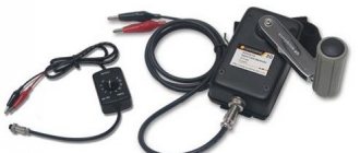
A small generator for a bicycle is mounted on the side wall of the tire. It allows you to charge the batteries of mobile phones, receivers and other devices, and lights up the headlights. A bottle dynamo is also called a side dynamo. When driving, the tire drives the dynamo roller, which rotates the electric generator.
For a bicycle generator, you can take a dynamo hub or a dynamo carriage. A non-contact dynamo will also work. She will be able to charge the phone quite successfully.
- A bottle generator creates resistance when running and requires more effort to turn than a hub dynamo. Proper adjustment will help reduce resistance.
- A bottle bike dynamo wears out the tire, unlike a hub dynamo.
- When wet, the dynamo bottle roller may slip over the tire, which will significantly reduce the amount of energy produced.
- A hub dynamo does not require good grip and sealing. They do not make noise like dynamos.
Required tools and components.
Tools needed to create
a USB dynamo charger:
Components needed to create
a universal dynamo powered USB charger:
Prices are low due to the components being ordered in large quantities. Your prices may vary.
Operating a Bicycle Dynamo
Careful installation of the dynamo is very important, taking into account angle, height and pressure. To start, the bottle style bicycle dynamo is moved and connected, and the hub dynamo is simply engaged manually or automatically.
The dynamo must be operated strictly according to the instructions.
- Before pedaling, check the voltmeter. It should show voltage (12-13).
- We select the low power mode, turn on the generator, the indicator light should light up.
- We pedal, gradually increasing the speed, until the generator turns on. The light went out, the voltmeter showed 13-14. The pedals must be pedaled quickly so that the circuit can maintain power.
- A bicycle dynamo works more efficiently when power is high. For heavy loads, it is better to start the generator at low power, and after disconnecting the load, switch to high power.
Dynamo charger
In field conditions, a simple “twist” or dynamo for charging your phone is always useful. Chargers with a built-in battery are popular. There are mechanical chargers that also do not take up much space. Many modern “spinners” are equipped with flashlights.
These devices charge mobile phones quite successfully. For example, when rotating the knob 2-3 revolutions per second, you can get a coefficient value from 0.65 to 2.5. Spin it for a couple of minutes and you can talk on the phone for 2 to 5 minutes. It all depends on the model and reception conditions. A handheld dynamo will not be able to power a powerful smartphone with a large display. Mechanical charging will provide results in conjunction with a simple phone along with a hands-free headset.
Dynamo charging will work effectively when the battery is completely discharged, but you can only increase the phone’s charge by twisting the handle up to 50%. When the battery is only half discharged, the spinner becomes a useless toy. If the instructions indicate a maximum charging current of 400 mA with a power of 2 W, then it will not be possible to squeeze out additional energy even if you quickly rotate the handle.
Powerful DIY generator
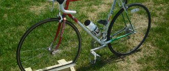
A powerful electricity generator can be assembled using an old bicycle without eights on the rear wheel. A 28-inch wheel and a 52-tooth front sprocket will do, but other options are possible, such as a 26-inch and a 46-tooth sprocket. First of all, we remove unnecessary parts: the front wheel, tires, gear shift, brakes. Place the bike on the stand.
The generator must be self-contained with two large terminals and one small one. We connect the two large terminals together to form a plus, and the small one with an indicator light. We connect the grounding terminal to the housing (minus). We clean the generator and remove the cooling fan from it. We fix the generator on a bracket behind the seat, the spindle should be outside 10-12 cm from the rim. We select a belt, preferably a toothed one, with a circumference of approximately 82 inches. For 26" wheels, A78 belts are suitable, and for 27" wheels - A80.
To adjust the tension of the alternator, we use a spring-type tensioner. The belt does not need to be tightened too much as the torque is quite low. We attach a voltmeter, a switch and a light bulb to the steering wheel. If there are children in the house, it is necessary to protect the moving parts of the mechanism to eliminate the possibility of injury.