Surely you are familiar with this situation: you put on your headphones, anticipating the enjoyment of your favorite melodies - and that’s it, we’ve arrived: you can’t hear anything. Or only one earphone works, which is even more annoying - the music seems to be playing, but you can’t listen to it properly.
If such problems occur, in most cases you can slightly tug the cable at the plug or set it in a certain position, gently squeezing the base until sound comes from both channels. This may help for a short time, but it gets pretty boring if you do it all the time.
The easiest way in this case is to give up and buy new headphones. The option, of course, is not bad, but what if it’s not just any ordinary headphones that are broken, but expensive and high-quality ones, and in general the most beloved and wonderful ones? The most annoying thing is that such symptoms, as a rule, do not indicate a breakdown of the headphones themselves, but damage to some contact, cable or plug-connector.
Replacing a plug is not particularly difficult or expensive. If you contact a master, they will ask for 300-500 rubles, depending on the fineness of the work. But if you are careful enough and your hands don’t shake too much, you can do everything yourself at home. But some preparations for repairs will have to be done, and even some components will have to be purchased. Standard contact plugs are sold in electronics stores for around a hundred rubles. The new plug almost always needs to be soldered to the wire. There are, of course, models that screw and clamp, but for headphones that are used with mobile devices, we do not recommend them.
So, for repairs we will need: a soldering iron, solder and skills to work with them. For greater effect, we recommend finding a piece of heat-shrinkable tubing to insulate live parts. The tube should tightly enclose the cable, additionally providing mechanical protection. In principle, heat-shrink tubing is the same as electrical tape, but it is much more convenient and more reliable.
Looking for the cause of the damage
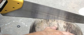
Admit it, how often have you seen a headphone cable break right in the middle? The cause of the breakdown is almost always the plug, which, with regular use, is subjected to mechanical stress much more often than other elements of the headphones. Simply squeeze and tug the wire around the plug.
If the sound appears after this, it means that there really is a problem. We simply cut off the old plug - we won’t need it anymore. Although, if the distance between the break and the flexible part of the plug is about cm, there is a chance to use it if it is not possible to buy a spare plug.
In addition, to more accurately determine the location of the break, you can use the tester in resistance measurement mode (Ohm). Touch one end of the plug to any of the plug contacts (the left or right headphone output is the two outermost contacts), and attach a simple needle to the other probe with electrical tape and carefully insert it into the wire a little further from the intended break point. If the tester shows a value of 0 or slightly more than zero instead of 1 (a value with hundredths or tenths), then there is a break in this wire.
We repair headphones
Stopped playing in one ear? Has it started rustling? Wait, throw it away, repair it! Below are typical headphone problems. In 99% of cases, one of the options is yours.
Internal break in the cord
Manifestations:
the sound begins to rustle in one of the headphones (less often in both), and over time disappears completely.
Diagnostics:
The break occurs at the bend of the cord, i.e. either directly at the connector, or at the wire entry into the earphone itself. You can accurately set the location if you turn on playback and rotate the cord. A cracking sound or sound indicates the exact location of the break.
Repair:
Cut the cord below the break point and solder it again.
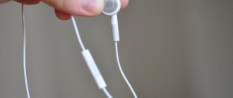
Option with a break at the connector
Plugs usually come in two types - solid, flexible plastic, a molded hard core, and a soft rubber cap.
It is necessary to remove the rubber cap; if this is not possible, cut it with a knife. Cut through the casting with wire cutters and get to the place where the wire is soldered to the metal contacts of the connector. Strip and solder the wire, and put everything back together.
Fill cavities due to removed plastic parts with epoxy glue, faster curing is better.
The cut elastic can be strengthened with bondage made from synthetic threads. Heat shrink tubing can also give good results.
Option with a break at the earphone
It is necessary to disassemble the earphone.
Large headphones are assembled with screws. Smaller headphones with clips. Headphones droplets, earbuds - adhesive connection. The adhesive joint is disassembled either with a knife, or by squeezing the headphones in a yew - due to elastic bending, the crack usually runs along the glued joint. The wire inside the earphone is tied in a knot to prevent it from being pulled out. Cut the wire, strip it, tie it in a knot and solder it as before. Glue the earphone back together.
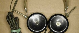
Channel blockage
This malfunction is only possible with closed acoustic earphones.
The membrane is separated from the channel by a thin metal mesh. Ear wax, as the earphone is used, covers this mesh and interferes with the passage of acoustic waves. Diagnostics:
absence of sound despite the fact that the continuity shows the integrity of the headphone windings.
Repair:
Disassemble the earphone and wash the mesh in alcohol. Disassembly is preferable so as not to stain the membrane with leaking alcohol and dirt particles.
Membrane damage
Manifestations:
crackling, rattling in one of the headphones, difference in playback timbre.
Diagnostics:
visual inspection and opening of the earphone.
Repair:
After opening, straighten the membrane if it is wrinkled. The effect will be temporary and the headphones will need to be replaced. If there are foreign particles on the membrane, remove them. Wash the mesh that separates the membrane from the surrounding space.
Why is this happening?
Let's look at the photo of the place where the cores broke:
With a small bending radius, the cores accumulate a large fatigue load and break. If you take a paper clip, straighten it and bend it in the middle, first in one direction, then in the other, then after several such bends it will break. The same thing happens with the conductors in the wire.
They fight this in two ways. At first, it is a special wire with a special weave of cores. The central channel made of synthetic threads provides the wire with tensile strength, and the wires wound in a spiral when the wire is bent experience more torsional load than bending. When loaded with torsion, the core is more stable. The second method is to increase the bend radius. To do this, the connector or earphone ends in an openwork flexible plastic structure, which, bending along with the wire, increases the bending radius. But correctly selected rigidity of the plastic is strictly necessary; if the plastic is too hard or too soft, the design will not be of any use.
Additional information: Basic information about soldering can be gleaned from the corresponding article. Information about the headphone device.
PS As usual, this is the only author's cross-post caused by the frailty of the project server. Original article here.
We check for quality
Upon completion of the operation, we need to check the functionality of the repaired headphones. We connect them to any player, smartphone or stereo system and turn on the music. Now, accidental touches to the cable should not cause any audible consequences, so we can only rejoice at the result.
How does a contact plug work?
Before you start soldering, it is useful to study the design of the stereo headphone plug. Below we offer a schematic representation of it. A headphone cable contains three wires: the right channel (usually red), the left channel (green, white or yellow) and ground (in our case copper-colored).
There is no separation between right and left channels on the mono headphone plugs. Depending on the plug, the contacts for soldering will be of different sizes. During soldering, try not to create electrical connections between the contacts, especially to ground, otherwise when you connect the headphones to the device, a short circuit will occur and they may fail. Therefore, in no case should you expose the ends of the cables (see point 2) more than is necessary for soldering.
First, let's look at the operation of the audio path.
On the left side of the board, three wires are soldered, coming from the headphones, which, along paths indicated by red lines, go to the two legs of the variable resistor. From the other two legs of the resistor, already in black lines, the tracks go towards the plug.
The microswitch is a bit of a nuisance, as it obscures the visibility of the tracks, but I didn’t unsolder it, and I don’t advise you to do so. Just take a multimeter and call them from start to finish. The “minus” or “common” track runs through the entire board without breaking off anywhere.
Now, if you apply a sound signal to the headset, then along the paths indicated by black lines it arrives at the resistor, and with two red lines, leaving the resistor, it goes to the headphones. A dual variable resistor is used here so that you can hear stereophonic sound, so it has five legs: two for input, two for output, and one for common (minus).
Although a conventional dual variable has six of them, in order to miniaturize and save material, one leg from each resistor is combined into one, since according to the circuit they are still connected together. To make it more clear to you, I present a schematic diagram of the sound path in compliance with all the colors used in the figure above.
As you can see, we identified three of the five wires leading out of the cable to the plug (jack) without difficulty, and in the next step we will figure out the remaining two.
We look carefully at the board and see that two tracks come from the microswitch legs, passing through two capacitors and a microphone. Here it turns out that all four elements are connected in parallel, and if you press the microswitch button, the entire circuit will be short-circuited and turn off the microphone from operation.
This leads to the conclusion that during a conversation, if you want to hear the interlocutor, you need to turn off the microphone by pressing a button. Here is a schematic diagram of the microphone and microswitch path.
Now I think that you will definitely figure it out when a problem arises with your favorite headphones. Using the described method, you can repair headphones of any complexity and complexity.
Introduction
The personal audio market is now broader than ever. One way or another, digital content is selling faster than hot cakes during a pandemic. And it’s more convenient to often consume it through headphones.
What technologies for creating headphone emitters exist.
- Dynamic emitters. Rubanoid is also here, as a variation on the theme. At the moment it's mainstream and you're most likely sitting in them.
- Magnetoplanar emitters. And also iso-, ortho- and so on. To prevent controversy, I used this concept for everything where there is a magnetic system and a flat coil corresponding to this magnetic system. As a variation on the theme of the so-called. Hale emitter, also called AMT, where the membrane is simply folded in a special way.
- Coils with a balanced armature, or, simply put, armatures. Often appear in in-ear headphones.
- Piezoelectric emitters. Rare in-ear models in the form of a high-frequency element.
- Electrostatic emitters. Extremely rare headphones for a lot of money, sometimes speakers.
- Tape emitters. Only one serial model of headphones and an infinite number of HF elements for stationary speaker systems.
- Other wonders, such as an electric arc emitter. Let's leave it to the conscience of the experimenters.
Almost all of these technologies should be multiplied by the number of all possible form factors (closed, open, in-ear and variations) and the number of current models will reach completely unknown heights.
You can try to cover up the problem of choice with a mountain of money. However, even in this case, high consumer qualities are not guaranteed at all, incl. and sound. For one single reason. When referring to scientific literature, for example, to Psychoacoustics Aldoshina I.A. and a number of articles, the absence of a unified standard for determining the quality of perception of sound systems will emerge. At the moment, all assessment of sound quality is carried out using indirect parameters and an expert method, which is given significant attention in this source. The second point here means significant subjectivity in expert assessment, since, among other things, it significantly depends not only on the skills and training of the expert, but also on his physical and psychological state. Of course, this cannot be verified and the output can be anything.
The described evaluation method is fraught with a double lottery. The same headphones, in order to get to you, must first be liked by an expert, and more than one. And then you will like it. And considering that during production, changes are constantly made to the design without any expert verification (well, we decided to save money), then in the end the choice turns into a coin toss, where you need to knock out six, seven, eight heads in a row.
Conclusions from the experience gained
In obtaining these ideas, I used the reverse method, identifying factors that clearly negatively affect sound reproduction.
- Smooth frequency response graph to maintain tonal balance
In fact, with good indicators of the following parameters, this one is also not bad.
- Smooth graph (important - without sharp peaks) of harmonic distortion
At the same time, achieving ultra-low distortions (less than 0.1%) does not make much practical sense. Another thing is that, as a rule, when distortion is reduced, other parameters also improve.
- High dynamic range at all frequencies, even outside the audible spectrum in both directions.
The emitter must overcome the internal forces of static friction in order to deviate from the equilibrium position. Thus, there is a limit to the required force to overcome static friction between layers of material. This parameter essentially defines the minimum dynamic range limit. It is determined by the materials and how they are connected to each other.
Taking magnetoplanar emitters as an example, one fact can be immediately established - they are multilayer. This is, as a rule, a layer of PET film or its analogues, optionally an adhesive layer and a layer of metal conductor. A properly made membrane must be corrugated so that its movement is freer. However, as for me, there is one problem with such a sandwich - in the environment of contact between the metal and the polymer film, a sharp abrupt change in mechanical parameters is formed, which, when oscillating, inevitably shift relative to each other, leading to energy losses. But that's half the trouble.
With a sufficiently small layer thickness, these losses can be minimized. The larger problem lies in the limited travel of this very membrane due to its strong tension. This tension is necessary to maintain the mechanical strength of the structure so that it does not sag or catch on the magnetic system. In addition, a loose or crooked membrane increases intermodulation distortion. As a result, summing up the presence of tension and friction losses, the output is not the highest dynamic range. Much wider than dynamic drivers, but still very narrow.
How to find out if the connector is faulty
Insert working headphones into the jack and turn on the music. If music does not play in working headphones, your connector is broken. Also, if you hear a hissing sound when the plug moves, this means that the connector will soon fail completely.
Useful: iPhone battery connector pinout and battery replacement
Nowadays, the pinout of headphone wires with a microphone shown in the first picture below is mostly used everywhere, but there is also another one, which is mainly used on old phones and in phones from some manufacturers. They differ in that the microphone and ground contacts are swapped.
Volume control problems
How to fix headphones if you have problems with the volume control in the form of loss of sound or crackling? In this case, you can use graphite lubricant to apply it to the resistive layer to restore contact. After this, the headset should function without problems.
If after lubrication the headset continues to work poorly, then the regulator needs to be replaced with a new one.
Thus, in most cases, before you run out and buy a new headset, you can repair it yourself. To do this, you will need a soldering iron with a thin tip and skills in handling it.
How to create wireless headphones
If a user wants to make wireless headphones for a PC at home, they will need to additionally purchase a Bluetooth modem for wireless communication and a battery.
Assembly:
- You need to disassemble the headphones and integrate the model and battery into them.
- The mod needs to be connected to the speakers, as well as the battery charging socket and the power button on the headphone body.
- After soldering and assembly, you need to insert the transmitting device into the computer socket, turn on the headphones, and wait for the Bluetooth connection.
Comic
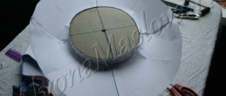
As you can see from the comic, by moving a soldering iron along a piece of pipe, you can bend it where and how we need. Then, by running a soldering iron over the surface, you can level it and give it the final look. When the desired shape is achieved, cut off the excess from the contact side.
In my opinion, such a connector is practically indestructible. It is much more likely that the wire will come out of position as it approaches the connector. And to reduce this probability, it was decided to use a spring. We will borrow it from a clicky ballpoint pen.
The spring should wind with difficulty, expanding at the connector. Then later, if you apply a soldering iron to it, it will shrink to its original diameter and melt into the connector.
Carefully!
The spring conducts heat very well and you can accidentally melt the wire sheath with it.
After everything that had been done, the thought came to me that it would be better if, before wrapping it in a plastic pipe, we put a 2-3 centimeter long thermal casing on the outgoing wire. In this case, you don’t have to worry about melting the wire braid when molding the connector and putting on the spring. Yes, and this would give it even more strength.
Ribbon emitters
This brings me smoothly to what, in my opinion, is the most promising technology in terms of dynamic range. Tape drivers. In ordinary life, they can be seen in some stationary speakers in the form of tweeters (high-frequency emitters).
In headphones, the ribbon type of emitter is practically not used. At least of all the serial factory models, there is only one representative of them - the Raal SR1A, and that one is obscenely expensive, moreover, it is not officially distributed in the CIS.
The tape driver is as simple as the corner of a house, even simpler. The simplest version of the emitter is two magnets, a piece of corrugated foil, that’s it. From an acoustics point of view, this is the most ideal option - the fewer parts and connections, the better. There are no obstacles along the route of the belt, except that there is some kind of protective mesh. In a more advanced design, you can add a magnetic circuit along the circuit to enhance the magnetic field in the work area.
The most important thing is that the dynamic range is head and shoulders better than anywhere else. The course of the tape can be anything, depending on how the tape is installed. But also with high frequencies, in stationary speakers such a radiator is used precisely in the HF section, it works just fine there. This is possible due to the isotropy of the tape itself. There is no interlayer interaction, glue, etc. Thus, the static friction force is limited only by the static friction force of a homogeneous metal. In a 15 micron aluminum layer these forces are extremely small. Simply due to the absence of extra layers in the form of films and glue, this emitter is better by default than a magnetoplanar one.
Naturally, there are nuances. The tape in such a radiator must be corrugated. Due to the elasticity of the metal, molded in the form of a wave (and this shape is needed so that the tape does not twist into a tube), the tape has such a large vibration amplitude. Therefore, it is necessary to make a tape that, when deflected in the emitter until it is completely straightened, does not go beyond its elastic limit in order to avoid plastic deformations. And a safety net against deformation is a small gap between the tape and the magnets to relieve excess pressure. In this case, the strength of the tape is almost comparable to the strength of the membrane of magnetic headphone. It may even slightly surpass it, at least experience shows that the planar membrane breaks precisely where there is no glue or metal, along the film. For example, the death of headphone membranes from the fairly well-known brand Audeze is a fairly common occurrence, and many forums record indignation from distressed owners. It is worth adding that we are always talking about the completely open design of the headphones, as the most advantageous from an acoustic point of view. Unfortunately, with closed models everything is more complicated, so as a standard of sound reproduction quality, I strictly consider models with an open lid.
It's better to buy headphones or make it yourself
It depends on how well you handle technology. If it’s easier for you to make your own headphones, then it’s better to buy the necessary components.
But you can buy inexpensive headphones that are of good quality, so you don’t need to waste effort. However, if you decide to make them yourself, then patience is required.
Checking the headphone pinout of non-standard connectors
In some mobile devices and GSM phones, in most cases, from previous years of production, phones with original special connectors were used. In such cases, using search engines you can find the original pinout of the headphone connectors. It may have different connection diagrams, for example, shown in the figure.
If the headphones of such devices fail, you can cut the headphone cable, purchase a new headset, and install new headphones in accordance with the diagram.
If there is no information on the Internet, you can independently determine the pinout of the headphones. To do this you need to do the following:
- disassemble the housings of the dynamic headphone system; for this you can use an active solvent;
- ring the terminals of the headphone speakers, zero resistance will correspond to the common wire;
- ring the contacts of the connector with the common wire, the contact number at which the multimeter shows a resistance close to zero will be the contact for connecting the common wire;
- similarly, you should make a call to the opposite contacts of the headphone speakers;
- for a headset with a microphone, search for connections to the connector contacts for each output separately.
Disassembling an old headset
To get all the necessary parts, they disassemble old headphones. You must act carefully, otherwise you may damage the parts. Large headphones have many hidden fastenings in the form of screws and latches. Most of them are hidden under a soft lining. The ear pads also come with snaps, they are simply put on the rim of the cup or glued. The body of the vacuum plugs will only have to be cut.
The old wire from the speakers is soldered off with a soldering iron. At the entrance to the housing, the integrity of the cores is compromised due to frequent kinks. If the cable is to be used for a new headset, then the ends, 5 cm long, are cut off and then the wires are soldered back to the speaker contacts.
A similar action is performed with the plug. If the mini-jack is non-separable, the casing is cut with a knife, and a new one is made from the cap of a ballpoint pen.
The wire on the headphones is broken: how to find the break and fix it at home
First you need to determine exactly whether the wire has broken or whether the failure of the electronic device is due to something else. To find a breakdown, you can use a multimeter or try to find a break mechanically. If everyone is familiar with the second method: just rub the wiring of both outputs and you can hear intermittent sound. The first method of determination requires skill in working with a multimeter.
Testing with a multimeter: basic procedure
Using a multimeter makes the process easier and faster. To search, you must:
- make small cuts in the top layer of insulation near the speaker and plug, then carefully remove the protective white or transparent layer;
- connect the black probe of the device to one cut, and the red one to the other, setting the desired voltage with the lever;
- If this section of the copper core is operational, then we continue searching until the device stops beeping.
You need to remove the braid from the cables using a special tool, because with a knife you can damage the conductor itself. It happens that the multimeter constantly makes a sound, so there is a possibility of suspecting a problem in the speaker or plug itself.
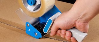
How to solder headphones so they work as before
A broken cable can be repaired, so don't rush to the store for new electronics. The only thing you may need (if you don’t have it at home) is rosin and tin (these are raw materials for soldering):
- Remove the insulating layer along with the protective layer using special nippers. In this case, you need to completely remove the entire braid.
- Next, cut the wires in the damaged area so as not to split them. The cut should be perfectly smooth.
- We heat up the soldering iron, meanwhile we reliably twist the cut wires so that the contacts correspond to each other.
- We apply solder to the soldering iron rod and process the pre-stripped conductors.
- Next, we heat up the thermal tubes (insulation for wires) and put them on the copper conductors, pay special attention to the soldering points. It is important to further isolate these areas.
The headset conductors have three interconnected cables inside: two audio outputs and one grounding. You need to be more careful with this arrangement.
Replacing the conductor in headphones: the basics of the process
If multiple damages are noticed on the conductor, then soldering alone is probably not enough. Most likely, this method will not solve the problem. Therefore, we will tell you how to replace a damaged cable with a new one:
- Choose unnecessary headphones, but with a working cable. To remove it, remove the insulating layer and carefully unsolder all connections.
- In order to remove the contacts on the audio outputs, you need to carefully open the case so as not to break the wiring; we repeat similar actions with the second contact.
- We unsolder the old wires from the desired headphones, then carefully place the new conductor into the housings for the “ears” and solder the contacts on the plug and near the speakers.
- Then we heat the insulating layer and put it on the conductors; we reinforce it with silicone tubes near the plug and auditory outputs.
- Let's connect the halves of the headphones using Moment glue.
HELPFUL INFORMATION! To ensure that the wiring is securely fastened and your headphones last longer, tie a knot in each headphone housing, without putting too much tension on the conductors. Clogs in the socket contacts can accumulate for years, so the device may require preventative cleaning after prolonged use.