Design features of the ionistor
In essence, this is an ordinary capacitor with a large capacity. But ionistors have a high resistance, because the element is based on an electrolyte. This is the first. The second is the low charging voltage. The thing is that in this supercapacitor the plates are located very close to each other. This is precisely the reason for the reduced voltage, but it is precisely for this reason that the capacitance of the capacitor increases.
Factory ionizers are made from different materials. The covers are usually made of foil, which is separated by a dry substance with a separating effect. For example, activated carbon (for large plates), metal oxides, polymer substances that have high electrical conductivity.
Assembling the ionizer with your own hands
Assembling an ionizer with your own hands is not the easiest thing, but you can still do it at home. There are several designs where different materials are present. We offer one of them. To do this you will need:
- metal coffee jar (50 g);
- activated carbon, which is sold in pharmacies, can be replaced with crushed carbon electrodes;
- two circles of copper plate;
- cotton wool
First of all, you need to prepare the electrolyte. To do this, you first need to crush the activated carbon into powder. Then make a saline solution, for which you need to add 25 g of salt to 100 g of water, and mix it all well. Next, activated carbon powder is gradually added to the solution. Its quantity is determined by the consistency of the electrolyte; it should be as thick as putty.
After which the finished electrolyte is applied to copper circles (on one side)
Please note that the thicker the electrolyte layer, the greater the capacity of the ionistor. And one more thing, the thickness of the applied electrolyte on the two circles should be the same
So, the electrodes are ready, now they need to be separated by a material that would pass electric current, but would not allow carbon powder to pass through. For this, ordinary cotton wool is used, although there are many options here. The thickness of the cotton layer determines the diameter of the metal coffee jar, that is, this entire electrode structure should fit comfortably into it. Hence, in principle, you will have to select the dimensions of the electrodes themselves (copper circles).
All that remains is to connect the electrodes themselves to the terminals. That’s it, the ionistor, made with your own hands, and even at home, is ready. This design does not have a very large capacity - no higher than 0.3 farads, and the charging voltage is only one volt, but this is a real ionistor.
general information
A very important fact. A capacitor has one property that manifests itself in an alternating current circuit. For such a circuit, this part will be a resistance, the value of which will depend on the frequency. If the frequency increases, the resistance will decrease, and vice versa.
There are basic units of measurement with which you can determine the identity of a particular capacitor. These include Farad, microFarad, etc. The designation on the elements of these units, respectively, is: F, μF.
Marking
There are three main parameters that characterize a capacitor: the nominal capacity, tolerance and nominal voltage. In most cases, two marking methods are used - alphanumeric and numeric.
In the first case, the letter denotes the capacitance value (μ, nF, pF) and plays the role of a decimal point. For example, if a non-polar capacitor is marked 1 μ, then it is a part with a capacity of 1 μF, and the inscription 3μ3 means 3.3 μF.
A letter encoding can be used to indicate tolerance; its decoding is presented in Figure 8.
Figure 8. Decoding of letter marking of tolerance
The operating voltage of the capacitance can also be indicated by a letter code; its decoding is given below.
Table: explanation of the letter marking of permissible voltage
Small containers, for example, in SMD version, are usually marked with a three-digit digital code.
Three-digit digital code for capacity parameter
In order not to remember all the table values, use the following decoding rule: the values are given in picofarads, the first and second values are the mantissa, the third is a power with a base of 10. For example, the inscription 331 will mean 330 pF (33*10).
A supercapacitor instead of a battery - a practical overview of supercapacitor assembly
In practice, such a device is capable of operating many times longer than batteries of various types, of course, subject to operation in certain modes. This is the peculiarity of using an ionistor instead of a battery and its advantage:
But the ionistor used instead of a battery has not only such features; I will tell you about them after assembling the drive.
Ionistor instead of battery - battery assembly procedure
In this review, I will assemble an energy storage device using eight capacitors connected in a back-to-back circuit. In principle, there will be four organized pairs of two containers connected in parallel, and the pairs, in turn, are connected in series.
The enameled wire must be leveled and the varnish removed from it. This is done using a working knife or a special tool for stripping wires (whoever has one).
We form copper wire into connecting bars
It is necessary to make three square elements and a pair of poles for the “+” and “-“ terminals
We solder the nuts to the formed contact products to which the power wires will be connected.
Tin the junctions of the squares.
We connect the containers into a battery, solder the conductors to the terminals of the capacitor, while observing the polarity.
First you need to assemble four groups.
Now we solder the busbars to connect the power wires.
At this stage, you need to charge the battery with a current of 5A.
After five minutes the drive will be fully charged.
We do a test test with an incandescent lamp.
We make a short circuit of the output contacts - the wire warms up to a red state.
We test the battery by connecting an electric motor.
Where is this design used?
You can use an ionistor instead of a battery where there are large and cyclic current loads. A classic example: a storage tank for a subwoofer installed in a car. In addition, a supercapacitor can be used in devices where constant charge/discharge cycles occur, for example: devices for storing solar energy with its subsequent transfer to lighting lamps at night.
Using an electrical double layer
For many decades, electrolytic capacitors had the highest capacity. In them, one of the plates was metal foil, the other was an electrolyte, and the insulation between the plates was metal oxide, which coated the foil. For electrolytic capacitors, the capacity can reach hundredths of a farad, which is not enough to fully replace the battery.
Large capacitance, measured in thousands of farads, can be obtained by capacitors based on the so-called electrical double layer. The principle of their operation is as follows. An electric double layer appears under certain conditions at the interface of substances in the solid and liquid phases. Two layers of ions are formed with charges of opposite signs, but of the same magnitude. If we simplify the situation very much, then a capacitor is formed, the “plates” of which are the indicated layers of ions, the distance between which is equal to several atoms.
Supercapacitors of various capacities produced by Maxwell
Capacitors based on this effect are sometimes called ionistors. In fact, this term not only refers to capacitors in which electrical charge is stored, but also to other devices for storing electricity - with partial conversion of electrical energy into chemical energy along with storing the electrical charge (hybrid ionistor), as well as for batteries based on double electrical layer (so-called pseudocapacitors). Therefore, the term “supercapacitors” is more appropriate. Sometimes the identical term “ultracapacitor” is used instead.
My Tesla laboratory. Variable capacitor
This product is not completely independent.
This is only part of a more complex device, a model that is intended to test the technology. But the recent publication by hamster76 - a wonderful radio receiver showed me that this development is worth sharing. That’s why I’m writing to “Help the Steam Master.” In his publication, hamster76 talked about his problems with a damaged capacitor, but a variable capacitor is a Tesla device in itself! A Teslapunk capacitor may well decorate any device. In the 20s, of the two methods of tuning the receiver - changing the inductance and changing the capacitance in the oscillating circuit, preference was given to changing the inductance. The first reason for this is theoretical: such a circuit potentially makes it possible to obtain a higher quality factor of the circuit and, as a consequence, better radio reception qualities. The second is technological. A variable capacitor is a complex mechanical device that requires high precision manufacturing. Already in the 30s, the situation changed - on the one hand, the technical capabilities of the radio industry increased, on the other hand, the spread of the superheterodyne reception circuit required synchronous restructuring of two circuits at the same time, and a dual variable capacitor turned out to be easier to manufacture than a dual variator. From then until the very end of the 20th century, a variable capacitor became an almost mandatory element of any radio device.
The main requirements for a capacitor are: 1) Continuity of electrical contact. At moments when the capacitor “comes off” from the circuit or, conversely, “short-circuits,” the radio listener hears very unpleasant clicks. 2) Smooth ride. With poor mechanics, it is very difficult to tune in to a station and “maintain the wave” in the future. 3) Large range of tunable capacity - allows you to capture more stations. 4) Low minimum capacity.
In order to avoid the problem of poor rotor contact, a contactless interaction scheme with the stator is used. The rotor plates are not connected anywhere, they interact with the stator only through the capacitance of the additional plates, this avoids the problem of poor contact. When the rotor turns, the capacitances between the plates are redistributed, and the total capacitance of the capacitor changes.
This design has disadvantages: the size of the plates is larger than in other schemes, the nonlinearity of the change in capacitance when the rotor is rotated, and the small “working range” of rotor rotation. The angle between the positions of maximum and minimum capacity is only 90 degrees.
But the design is very simple, without moving electrical contacts. In addition, the symmetry of the design greatly facilitates the design of the rotary axis.
The capacitor consists of a wooden base - a stator and a handle rotating on an axis - a rotor. They are cut from the board using crowns and turned on the axis of the drill. The stator diameter (this, however, is not at all important.) is 120 mm, the rotor diameter (but this affects the maximum capacity!) is 80 mm. An insulating gasket made of thin cardboard is inserted between the stator and the rotor. Identical semicircular plates made of tin are fixed (with small nails) on both the stator and the rotor; the stator plates are connected by wire to terminals. The axle is made of a screw with a slippery plastic tube attached to it. At the bottom of the axis, in the stator recess, there is a conical spring taken from the battery container. The spring ensures uniform compression of parts and uniform rotation. The structure is secured at the top with a decorative nut.
The resulting capacitor has a capacity of 6-30 pF. It's not very much. The tuning range for long and medium waves should be about 40, for ultrashort waves - 10. The easiest way to improve performance is to increase the size. Increasing the size of the plates will increase the maximum capacity. In addition, it turned out that most of the minimum capacitance is the capacitance of massive terminals located too close to each other. Connections to the plates should be made at the maximum distance from each other.
Connection diagrams
wiring diagram for an electric motor with a starting capacitor
The circuit that has a starting capacitor in the network has become more widespread.
This scheme has certain nuances:
- The starting winding and capacitor are turned on when the engine starts.
- The additional winding operates for a short time.
- The thermal relay is included in the circuit to protect the additional winding from overheating.
If it is necessary to provide high torque during startup, a starting capacitor is included in the circuit, which is connected together with the working capacitor. It is worth noting that quite often its capacity is determined empirically to achieve the highest starting torque. Moreover, according to the measurements taken, the value of its capacity should be 2-3 times greater.
The main points of creating an electric motor power circuit include the following:
- From the current source, 1 branch goes to the working capacitor. It works all the time, which is why it got its name.
- In front of it there is a branch that goes to the switch. In addition to the switch, another element can be used that starts the engine.
- A starting capacitor is installed after the switch. It operates for a few seconds until the rotor picks up speed.
- Both capacitors go to the motor.
In a similar way, you can connect a single-phase electric motor.
It is worth noting that the working capacitor is present in the circuit almost constantly. Therefore, it is worth remembering that they must be connected in parallel.
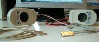
First test with engine start
I bought 6 supercapacitors and a balance protection board, sometimes they are sold individually for each ionistor, and sometimes there is a whole line for six pieces.
Put it all together.
The protection board prevents overcharging of supercapacitors with voltages above 2.7V, so it is almost mandatory to use it if the elements are connected in series.
Next, I soldered the terminals and installed this battery on the car. But first it must be charged with a small current of 5-7 A to operating voltage. This took 10-15 minutes.
After connecting, the car started up without unnecessary difficulties, the engine ran stably, and the voltage in the on-board network was kept at the proper level.
During this experiment, the following advantages and minutes were revealed: the battery of ionistors quickly discharged when the ignition was turned off, namely, after about 5-6 hours, the voltage dropped to 10 V. This was a minus, but the plus was that even at this voltage the car still started, since for the ionistor any voltage is working, unlike the battery.
As a result, it was no longer possible to start the engine after one day. And I decided to correct this shortcoming in the next design.
Application
The scope of application of ionistors is quite extensive, but most often they are used as an emergency or backup power supply for a timer or memory chips in various devices, from telephones to stereo systems, televisions, video cameras, etc.
Video: efficiency in using an ionistor
Quite exotic experiments were also carried out on the use of supercapacitors, in particular, on their basis they tried to create a Gauss weapon (electromagnetic gun).
A typical connection diagram for supercapacitors as power sources is shown in the figure.
Backup power connection diagram
Designation on the diagram:
U – connection to the main power source;
D1 – a diode that prevents leakage of the ionistor charge when there is no main power supply;
R1 – resistor, serves two purposes:
- charging current limitation;
- eliminates overload of the main power source when the voltage is turned on;
C – backup power supply based on an ionistor;
Rn – load resistance.
Note that you can do without a resistor (designated on the diagram - R1) if the characteristics of the power source allow a short-term increase in the load current to 250 mA.
In addition to the given example of household use, ionistors can be used to connect an LED in a low-power flashlight, and charging can be done from the energy of a solar battery.
Let's give another common example of using this device to start a car engine. A diagram of such an implementation is shown in the figure.
Diagram: starting device for a car engine
This scheme can be implemented on any passenger car where the on-board voltage is 12V, symbols in the figure:
- 1,2, 3 – connection terminals (1 to the positive contact of the battery, 2 to the negative, 3 is connected to the ignition switch);
- Ks – ignition switch;
- B1 – car battery;
- K1, K1.1 – contactor and its control key;
- C - supercapacitor;
- Rc is a resistor that limits the charging current of ionistor C.
The circuit uses a supercapacitor (marking: 12PP-15/0.002), which has the following characteristics:
- maximum rated voltage – 15V;
- capacity – 216F;
- internal resistance value – 0.0015 Ohm;
- rated current – 2kA.
The characteristics listed above will be sufficient to start an engine with a power of up to 150 hp. The charging time of the ionistor is no more than 5 seconds; after turning on the starter, during the first few seconds the main current load will go to the supercapacitor, since the internal resistance of the battery is higher.
A similar starting device that uses an ionistor can be purchased ready-made, but making it yourself will cost much less.
PDA design
In order to change or determine the capacitance of a variable capacitor of this type, it is necessary to rotate the rotor. If we talk about the simplest equipment, then it most often uses a wire tuning capacitor. This part consists of a piece of copper wire with a diameter of 1-2 mm. The length of this element is 15-20 mm. An insulated wire with a diameter of 0.2-0.3 mm is wound onto the wire very tightly, turn to turn. In order to change the capacitance in this device, it is necessary to unwind the wire. To prevent the winding from slipping off at this time, it is necessary to impregnate it with any insulating compound.
Other verification methods
You can check the capacitor without removing it from the microcircuit. To do this, you need to connect a known good capacitor with the same capacitance in parallel. If the device works, then the problem is in the first element and it should be changed. This method is applicable only in circuits with low voltage!
Sometimes the capacitor is checked for a spark. It needs to be charged and a metal tool with an insulated handle to close the terminals. A bright spark with a characteristic sound should appear. If the discharge is low, we can conclude that it is time to change the part. This measurement must be carried out wearing rubber gloves. This method is used to test powerful capacitors, including starting capacitors, which are designed for voltages of more than 200 Volts.
It is not advisable to use testing methods without special instruments
They are unsafe - with the slightest carelessness you can get an electric shock. The objectivity of the picture will also be impaired - exact values will not be obtained
Accumulated energy
The amount of energy stored in a capacitor, expressed in joules:
E = CU 2 /2, where C is the capacitance, expressed in farads, U is the voltage on the plates, expressed in volts.
The amount of energy stored in the capacitor, expressed in kWh, is:
W = CU 2 /7200000
Hence, a capacitor with a capacity of 3000 F with a voltage between the plates of 2.5 V is capable of storing only 0.0026 kWh. How does this compare to, for example, a lithium-ion battery? If we take its output voltage to be independent of the degree of discharge and equal to 3.6 V, then an amount of energy of 0.0026 kWh will be stored in a lithium-ion battery with a capacity of 0.72 Ah. Alas, a very modest result.
Options
Ionistors have the following characteristics:
- Internal resistance (measured in milliohms).
- Maximum current. (A).
- Rated voltage (V).
- Capacity (F).
- Self-discharge parameters.
Activated carbon or foamed carbon are used as electrodes in the device. These components are placed in an electrolyte. The separator is designed to protect the device from short circuit of the electrodes. Modern devices do not use an electrolyte based on an acid or a crystalline alkali solution, since these components have a high level of toxicity.
The internal cavities of the structure contain an electrolyte that stores electricity when interacting with the plates. The first electrochemical ionistors (molecular energy storage devices) were developed more than 50 years ago. They were made on the basis of porous carbon electrodes. They are currently used in some electrical appliances. Compared to lithium-ion batteries, modern ionistors are characterized by a longer service life and a high discharge rate.
When using ionistors, you can achieve a more economical operating mode by accumulating excess energy. Between the plates of the structure there is not a standard layer of dielectric, but a thicker layer, which makes it possible to obtain a thin gap.
At the same time, the device provides the ability to generate electricity in large volumes. A supercapacitor stores and drains charge faster than alternatives. The double layer of dielectric increases the area of the electrodes. This allows for improved electrical performance.
Bundle of six ionistors
Resistance capacitance of a capacitor in an alternating current circuit
It is important to note here that current in a circuit in which there is a capacitor can only flow if the applied voltage changes. You also need to understand that the strength of the current that will circulate in the circuit during the discharge and charge of this element will be greater, the greater the capacitance of the capacitor itself, and will also depend on the speed at which changes in the electromotive force (EMF) occur.
One more property. A capacitor with variable capacitance, which is connected to a circuit with alternating current, will be a resistance for this circuit. In other words, the value of the capacitance resistance will be the smaller, the greater the value of the capacitance itself and the higher the frequency of the operating current. However, this statement is true only for a circuit in which the current is alternating. The capacitance of the capacitor is equal to infinity, that is, its resistance will be infinite if such an element is placed in a circuit with direct current.
Internal device
Ionistors differ from capacitors in that their design does not involve the use of a dielectric between the electrodes; in the manufacture of the latter, substances with opposite charge potentials are selected. A simplified design of these radio components is shown in the figure.
The design of classic ionistors
Legend:
- a, b – electrodes;
- c – separator;
- d – activated carbon.
The capacitance of the capacitor depends on the area of the “lining” of the capacitor; it is for this purpose that activated carbon or foamed carbon, which are placed in the electrolyte, are used as electrodes in devices. The purpose of the separator is to prevent short circuiting of the electrodes.
The electrolyte can be a solid or crystalline solution of an alkali or acid. Note that in modern products this type of electrolyte is not used due to its high toxicity.
The figure below shows, as an example, the design of EN series ionistors manufactured by Panasonic.
EN series design
The figure shows:
- a – electrodes (the material is activated carbon);
- b, e – upper and lower parts of the body;
- c – separator;
- d – sealing insulator.
Scheme
Here is a diagram of the second battery prototype.
Let me make a reservation right away: it does not have a solar panel or a second battery. It also uses a line of supercapacitors with a balanced board. Also added is a battery charge controller, a pair of switches, a voltmeter and a small battery with a capacity of 7.5Ah. The operation of the device is as follows: before starting the car, open the hood and press the top switch according to the diagram. Through a powerful 50 Watt resistor with a resistance of 1 Ohm, the ionistor begins to charge from the battery. You cannot charge directly without this resistor, as this will be tantamount to a short circuit for the battery.
Everything takes 15 minutes. For me this is not critical. After this, you can start the car and drive. A Schottky diode is also connected in parallel to the resistor. It serves to charge the battery after the engine is started. And the battery is charged through the charging controller.
It is needed so that you don’t have to click the power switch every time, but turn it on once and go: stand at the store and leave for a couple of hours. And if the ionistor begins to draw current from the battery and discharge it below 11.4 V, the charging controller will immediately turn it off. This will protect the battery from being completely discharged, which could destroy it ahead of schedule. The switch at the bottom of the diagram is used to connect the voltmeter either to the ionistors or to the battery.