Main characteristics
In order to determine the feasibility of manufacturing a generator using neodymium magnets, you need to consider the main characteristics of this material, which are:
- Magnetic induction B is a strength characteristic of a magnetic field, measured in Tesla.
- Residual magnetic induction Br is the magnetization possessed by a magnetic material when the external magnetic field strength is zero, measured in Tesla.
- Coercive magnetic force Hc - determines the resistance of a magnet to demagnetization, measured in Amperes/meter.
- Magnetic energy (BH)max - characterizes how strong the magnet is.
- Temperature coefficient of residual magnetic induction Tc of Br – determines the dependence of magnetic induction on the ambient temperature, measured as a percentage per degree Celsius.
- Maximum operating temperature Tmax - determines the temperature limit at which the magnet temporarily loses its magnetic properties, measured in degrees Celsius.
- Curie temperature Tcur - determines the temperature limit at which a neodymium magnet is completely demagnetized, measured in degrees Celsius.
The composition of neodymium magnets, in addition to neodymium, includes iron and boron and depending on their percentage, the resulting product, the finished magnet, differs in classes, differing in their characteristics given above. A total of 42 classes of neodymium magnets are produced.
The advantages of neodymium magnets that determine their demand are:
- Neodymium magnets have the highest magnetic parameters Br, Hsv, Hcm, VN.
- Such magnets have a lower cost compared to similar metals containing cobalt.
- They have the ability to operate without loss of magnetic characteristics in the temperature range from – 60 to + 240 degrees Celsius, with a Curie point of +310 degrees.
- From this material it is possible to make magnets of any shape and size (cylinders, disks, rings, balls, rods, cubes, etc.).
Wind generator on neodymium magnets with a power of 5.0 kW
Currently, domestic and foreign companies are increasingly using neodymium magnets in the manufacture of low-speed electric current generators. Thus, Salmabash LLC, Gatchina, Leningrad Region, produces similar permanent magnet generators with a power of 3.0-5.0 kW. The appearance of this device is shown below:
The generator housing and covers are made of steel, later coated with paint and varnish materials. The housing is equipped with special fastenings that allow you to secure the electrical device to the supporting mast. The inner surface is treated with a protective coating that prevents metal corrosion.
The generator stator is made of electrical steel plates.
The stator winding is made of enamel wire, allowing the device to operate for a long time at maximum load.
The generator rotor has 18 poles and is mounted in bearing supports. Neodymium magnets are placed on the rotor rim.
The generator does not require forced cooling, which is carried out naturally.
Technical characteristics of the 5.0 kW generator:
- Rated power – 5.0 kW;
- Rated frequency – 140.0 rpm;
- Operating rotation range – 50.0 – 200.0 rpm;
- Maximum frequency – 300.0 rpm;
- Efficiency – not less than 94.0%;
- Cooling – air;
- Weight – 240.0 kg.
The generator is equipped with a terminal box through which it is connected to the electrical network. The protection class corresponds to GOST 14254 and has a degree of IP 65 (dust-proof design with protection from jets of water).
The design of this generator is shown in the figure below:
where: 1-body, 2-bottom cover, 3-top cover, 4-rotor, 5-neodymium magnets, 6-stator, 7-winding, 8-coupling half, 9-seals, 10,11,12-bearings, 13 - terminal box.
Technological section of a linear generator
The engine housing 1 is welded steel, cylindrical, has inside supports 2, 3 and 4 for installing the working cylinder sleeve 5. The sleeve is secured with a pressure ring 6 on 8 studs. The studs are mounted in a thick-walled foundation slab 7. Next, a cylindrical water manifold 8 is put on the bushing. After the manifold, a gas exhaust manifold-volute is put on the cylinder bushing 9.
The groove of the bushing and volutes on the seating surfaces are designed in such a way that a heat-resistant asbestos printed gasket is clamped between the steps. The snail heats up during operation and can expand in a linear direction. To allow expansion, the volute is mounted on long pins 10, passing through tubes 11, with nuts 12, which create a pressing force on the volute through springs 13. Afterwards, a water manifold 14 is placed on the volute.
The sleeve of working cylinder 5 is solid. The central part of the bushing has a thickening in the same way as in the place where the bushing is attached - ridge 15. In the central part, the bushing has holes for 2 pump injectors 16. The bushing also has 6 holes on each side of the center for lubricant fittings ( not shown in the drawing). In the bushing in the central part there is a cylindrical groove externally made to drain and collect cooling water from the tangential drillings of the cooling channels 17. The bushing has 17 grooves for the rubber sealing rings of the cooling system. There are tangential windows located in the bushing on the exhaust side and on the blowing side.
The linear generator has a power welded housing 18 and a lightweight housing to ensure the safety of operating personnel. The lightweight housing is closed at the ends of the engine with 18 covers on the flanges.
The piston group of each linear generator consists of 2 pistons 20. The internal piston is attached to the inductor body 21 on 8 studs 22. The outer piston is attached to the traverse disk 23 on 8 studs 24. The cylindrical traverse disk is supported in a radial direction with triangular gussets 25 on both sides, which are secured by welding. Each piston has 6 rings: 4 compression and 2 oil scraper rings. To avoid the pistons hitting each other at high compression ratios in a linear generator, the piston heads have a flat configuration.
The pistons are water cooled. Water is supplied to the external pistons through an internal telescopic fixed tube 26 with a nozzle at the end. Cooling water returns through the telescopic middle tube 27. Tube 27 moves in a stationary tube 28. Between tubes 27 and 28 there are seals 29.
The internal piston is also cooled by water. Water is supplied through a telescopic tube 30, which is attached to the inductor body 21 using a flange. There is a channel in the inductor and in the piston support flange. Next, the water moves through tube 31 and cools the piston. The water returns through tube 32, and the already heated water is discharged along a similar path and through telescope 33.
The external pistons are connected to each other by means of a traverse disk 23, 6 rods 34 and an inductor housing 35. The ends of the rods are threaded and secured with nuts clamped by a hydraulic jack. The movement of the internal and external piston groups is shifted by 180 degrees. Synchronization is ensured by a synchronizer mechanism - 3 gears 36 6-tooth racks.
Three slats 37, belonging to the internal group, have a cylindrical cross-section in the part closest to the inductor body 21 and pass through the seals 38. Next, the cross-section of the slats becomes square. The racks belonging to the outer group are 3 of the 6 rods 34, to which the gear racks are attached with bolts. All 3 synchronizer mechanisms are located in separate enclosures and contain oil to lubricate the mechanism.
Comparison of LG and traditional diesel.
- In LG, the production and assembly of the engine is significantly simplified due to the absence of such expensive and difficult-to-manufacture parts as a camshaft and crankshaft.
- Reduced fuel consumption due to increased mechanical efficiency due to the absence of a crankshaft and camshaft.
- Reduction of vibration due to mutual damping of emerging inertial forces.
- Increased reliability of the LG due to a reduction in the number of moving parts.
- In the LG it is impossible to ensure an even sinusoid of the generated current due to the uneven speed of movement of the magnets relative to the coils. But at the current level of development of conversion technology, this problem is not insoluble.
- Increased instability of the LG operation due to the presence of only two cylinders and the absence of a flywheel. If a flash is missed in one of the cylinders, the LG will stop, since in the second cylinder the air will not be compressed sufficiently to ignite the fuel. Therefore, to solve this problem, it becomes necessary to install at least two injectors per cylinder.
Oleg Gunyakov
Advantages and disadvantages
The advantages of wind generators made using neodymium magnets include the following characteristics:
- High efficiency of devices, achieved by minimizing friction losses;
- Long service life;
- No noise or vibration during operation;
- Reduced costs for installation and installation of equipment;
- Autonomy of operation, allowing operation without constant maintenance of the installation;
- Possibility of self-production.
The disadvantages of such devices include:
- Relatively high cost;
- Fragility. Under strong external influence (impact), a neodymium magnet can lose its properties;
- Low corrosion resistance, requiring special coating of neodymium magnets;
- Dependence on operating temperature – when exposed to high temperatures, neodymium magnets lose their properties.
Operating principle of the Adams fuel-free generator
One of the most popular models converts energy into induced current. It was first built by the scientist Adams, in whose honor it received its name.
Diagram of a simple fuel-free generator (Bedini has the same principle of operation):
The basic components of the Adams unit are as follows:
- a generator within which an electromagnetic field arises;
- an inverter that converts magnetic pulses into alternating current;
- batteries that store energy for later use.
The operating principle of the device is based on the phenomenon of electromagnetic induction. The rotation of the motor depends on the force with which it is repelled from the poles of the magnets. The main structural element is a multi-pole direct rotation gearless generator. The magnets are installed on the outer edge of the generator. Their number depends on the desired power. Such units have a very high efficiency - about 90%. If necessary, they are well connected to each other, forming a single autonomous network.
Phases - which is better - three or one?
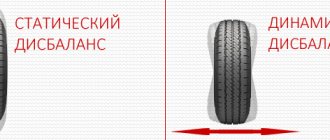
Many lovers of electrical equipment follow the path of least resistance and, in order not to bother, opt for a single-phase stator for a windmill. However, it has one unpleasant feature that neutralizes the ease of assembly - vibration when loaded, due to the variability of current output. After all, the amplitude of such a stator is abrupt, reaching a maximum when neodymium magnets are located above the coils, and then dropping to a minimum.
But when the generator is made using a three-phase system, there are no vibrations, and the power indicator of the windmill has a constant value. The reason for this difference is that the current, falling in one phase, at the same time increases in the other. As a result, a wind generator operating in a three-phase system can be up to 50% more efficient than the exact same one using a single-phase system. And most importantly, a loaded three-phase generator does not produce vibration, therefore, the mast does not give rise to complaints about the wind generator to the supervisory authorities from ill-wishers among neighbors, since it does not create an annoying hum.
Features of the rotor and stator
Transistor generator
To make an effective generator using neodymium alloy magnets with your own hands, consider the following recommendations when assembling:
- To increase strength, the disc is made of steel. Its thickness is made no less than that of the magnets themselves. Otherwise, part of the force field will dissipate. If the proportions are observed correctly, the sewing needle will not be attracted to the reverse side of the assembled product;
- The distance between individual magnets is made equal to or more than half the width of the products;
- The thickness of the assembled stator is made equal to or less than the thickness of neodymium magnets;
- A three-phase magnetic generator is made in proportions of 3 to 3 or 4 to 3 (the number of magnets/induction coils, respectively).
For your information. The magnets are attached, strictly observing the alternation of poles. To avoid mistakes, marks are made in advance with a marker on the corresponding edges.
Generator operating principle
On an industrial scale, electricity is generated using fuel, which when burned releases energy that is converted into electricity. When developing their devices, the creators of modern fuel-free generators want to eliminate the intermediate link - fuel.
Thus, the creators of generators eliminate additional chains of transformations, trying to immediately convert one type of energy into another.
The operating principle of the generating device is to generate electric current by forming a directed flow of charged particles in a conducting medium. Influence can be exerted in the following ways:
- create an external alternating magnetic field that induces an EMF in the conductor;
- maintain a potential difference at the ends of the conductor;
- transfer the conductive medium to self-generation mode, when the released energy is more than required to maintain the process.
What unites all generators on any principle of operation is the need to supply a certain starting amount of energy to start the process.
In the description of any generator without fuel, the source of energy, the process of its extraction, as well as further transformation are not given or are given in general statements.
Rotor creation process
The author of the development decided to make the basis of the generator a car hub with brake discs, since it is powerful, reliable and perfectly balanced.
When you start making a windmill with your own hands, you should first prepare the base for the rotor - the hub - and clean it of dirt, paint and grease. Then start gluing the permanent magnets. To create this wind generator, twenty of them were used on a disk. The size of the neodymium magnets was 25x8 millimeters. However, both their number and their size can vary depending on the goals and objectives of the person creating the wind generator with his own hands. However, to obtain one phase it will always be correct to equalize the number of poles to the number of neodymium magnets, and for three phases to maintain the ratio of poles and coils - two to three or three to four. The magnets should be positioned taking into account the alternation of poles, and as accurately as possible, but before you start sticking them, you need to either create a paper template or draw lines dividing the disk into sectors. To avoid mixing up the poles, we make marks on the magnets. The main thing is to fulfill the following requirement: those magnets that stand opposite each other must be turned with different poles, that is, attract each other.
The magnets are glued to the disks using super glue and filled in. You also need to make borders along the edges of the disks and in their center, either by wrapping tape or molding them from plasticine to prevent spreading.
Modification of a car generator
Creating a permanent magnet rotor requires quite a serious intervention in the design. It is necessary to reduce the diameter by the thickness of the magnets plus the thickness of the steel sleeve, which is placed on the rotor to form a continuous magnetic flux and at the same time serves as a landing pad for the magnets. Some experts do without a sleeve, installing magnets directly on the rotor with a reduced diameter and fixing them with epoxy.
The manufacturing process requires the participation of production equipment. The rotor is clamped into the lathe and the layer is carefully removed so that the installed magnets rotate with minimal clearance, but quite freely. The magnets are installed on the rotor plates with alternating polarity.
The greatest effect can be achieved when installing relatively small-sized magnets arranged in rows in the longitudinal direction. A smooth and powerful magnetic flux is achieved, acting on the stator power windings with uniform density at all points.
Making a rotor from a hub and brake disc
The considered method applies to ready-made generators that require minor design changes. Such devices include car generators, which are often used by amateur designers as a basic device. Often, generators are assembled completely independently, without having a ready-made device.
In such cases, they act somewhat differently. The basis is a car hub with a brake disc. It is well-balanced, durable and adapted to certain types of loads. In addition, the size of the hub allows a large number of magnets to be placed around the circumference, allowing three-phase voltage to be obtained.
Magnets with alternating polarity are placed at a distance equidistant from the center. Obviously, the highest number can be set by gluing them as close to the outer edge as possible. The most accurate indicator will be the size of the magnets, which will determine the possibility of placement at a certain distance. The number of magnets must be even so that the rhythm of alternating poles during rotation does not break down.
Gluing magnets to the hub is done using any glue; the best option is epoxy resin, which is used to completely fill the magnets. This protects them from moisture or mechanical stress. Before pouring, it is recommended to make a plasticine rim along the edge of the hub to prevent the epoxy from flowing down from the hub.
The design of the generator on a car hub is most convenient when making a vertical windmill. It is noteworthy that a similar scheme can be used without a hub, on a disk cut from ordinary plywood. This design is much lighter, allows you to choose a convenient size, which makes it possible to create a sensitive and productive device.
Overview of BTGs and their schemes
Today there are quite a large number of fuel-free generators of various designs and operating principles. Of course, not all models and the principle of their operation were covered by the creators for the general public. Most fuel-free generators remain a secret, sacredly protected by their creators and patents. We can only analyze the available information about the principle of their action and general information about their effectiveness.
Adams generator - "Vega"
A fairly effective magnetic-type generator invented on the basis of the theory put forward by scientists Adams and Bedini. The operation of the generator is based on a rotating magnetic rotor, which is made up of permanent magnets with the same pole orientation. When the rotor rotates, a synchronous magnetic field is created, which induces an EMF in the stator windings. To maintain rotor torque, short-term electromagnetic pulses are applied to it.
The industrial implementation of this principle was given to the Vega generator, which comes from the abbreviation Vertical Adams Generator, which is intended for power supply to private houses, cottages, and shipping facilities. Due to short-term pulses at the output, a pulsating voltage is created, supplied to the batteries for charging, and from them inverted into an alternating voltage of industrial frequency. But the question of whether the declared parameters correspond to its real capabilities is quite controversial.
Tesla Generator
It was patented by a famous Serbian physicist more than a hundred years ago. The principle of operation is the presence of electromagnetic radiation in the Earth's atmosphere, while the planet itself represents a much lower level of potential.
Rice. 1. Schematic diagram of the Tesla generator
Look at the picture, the Tesla fuel-free generator conditionally consists of the following parts:
- Radiation receiver - made of conductive material located on a dielectric base. The receiver must be isolated from the ground and placed as high as possible;
- capacitor (C) – designed to accumulate electrical charge;
- ground electrode – designed for electrical contact with the ground.
The principle of operation is that the receiver receives electromagnetic energy, which begins to flow through a closed circuit to the ground. But, due to the presence of a capacitor, the charge does not flow down the ground electrode, but accumulates on the plates. When connecting a load to a capacitor, the device will be powered by discharging the capacitor. In addition, the design can be supplemented with automation and converters for continuous power supply along with recharging.
Generator Rossi
The operation of this fuel-free generator is based on the principle of cold nuclear fusion. Despite the absence of classical turbines driven by steam or combustion of petroleum products, for its operation, instead of burning fuel, a chemical reaction between nickel and hydrogen is used. In the chamber of the Rossi generator, an exothermic reaction occurs with the release of thermal energy.
It should be noted that for the reaction to proceed normally, a catalyst is used and electricity is consumed. According to Rossi, the amount of thermal energy generated is 7 times greater than the electricity consumed. This model is already beginning to be implemented for heating areas and generating electricity. But, since for operation it is still necessary to refuel the installation with working reagents, it cannot be called completely fuel-free.
Hendershot Generator
The principle of operation of this fuel-free generator was proposed by Lester Hendershot and is based on the conversion of the Earth's magnetic field into electrical energy. The scientist proposed a theoretical justification for the model back in 1901 - 1930, it consists of:
- electric coils in resonance;
- metal core;
- two transformers;
- capacitors;
- permanent magnet.
For the circuit to work, the orientation of the coils must be observed from north to south, due to which the magnetic field will rotate, which will generate an EMF in the coils.
Mark Hendershot, son of Lester Hendershot presents his BTG
There is also a diagram of this BTG circulating online (picture below). How true it is, I cannot say.
Hendershot generator circuit
Generator by Tariel Kapanadze
Our contemporary claims that he discovered the possibility of obtaining electrical energy from the ether, working with Tesla coils and continuing the research of the famous scientist. Kapanadze's fuel-free generator consists of a Tesla coil, a block of capacitors, a battery and an inverter, but this arrangement is just a guess; the inventor himself keeps the design of the fuel-free generator in the strictest confidence.
Rice. 2: general view of the Kapanadze generator
Look at Figure 2, it shows a general view of the free energy generator. Today there are rumors about an attempt to sell the device on a large scale for the needs of consumers in some countries, but they have not been able to achieve the final result.
The electrical circuit of this generator also circulates on the network (figure below). But we cannot say how true it is.
Electrical circuit of the Kapanadze generator
Khmelevsky generator
According to the official version, Khmelevsky’s fuel-free generator was discovered by accident, since the creator conceived it as a power supply for converting direct current into alternating current. But it found wide application in geological exploration and became widespread in expeditions moving away from sources of central power supply.
Such a fuel-free generator consists of a transformer with split windings, resistors, capacitors and a thyristor. Electricity is generated due to the special design of the transformer itself, which can create a counter EMF greater than that at the input. This result is achieved due to the resonance effect and the application of a voltage of a certain frequency and amplitude.
John Searle Generator
The fuel-free Searle generator is based on the principle of magnetic interaction between the core and the rollers. In which magnetic rollers are placed at an equidistant distance and tend to maintain their position after the system is set in motion. The magnetic motor includes a multi-component fixed core, around which the same multi-component rollers rotate. There are coils installed along the diameter around the rollers, in which an EMF is generated when a magnetic roller passes near them. To start the device, starting electromagnets are used, which supply pulses that drive the rollers.
Rice. 3: general view of the Searle generator
According to Searle, the rollers independently increase the rotation speed due to the alternating magnetic field created by the different polarity combination of magnets inside the rollers and inside the stationary core. When manufacturing a structure in three levels, the rotation speed leads not only to the generation of electricity, but also reduces the weight of the device, up to an anti-gravity effect.
Romanov generator
The operating principle of the Romanov fuel-free generator is to apply standing waves to one of the capacitor plates, while the second plate is directly connected to the ground.
Rice. 4: operating principle of the Romanov generator
Look at the figure, here is the principle of operation of the device; when one plate is connected to the ground, a certain charge arises on it. Standing waves on the second plate generate a potential that is significantly different from the ground potential. Coils with multidirectional winding act as a standing wave generator, in which eddy currents compensate for the active component of the current. After accumulating charge, the capacitor can be used to power electrical appliances as a load.
But it was not possible to achieve unambiguous success for domestic or industrial purposes in the implementation of this model.
Schauberger generator
Such a fuel-free generator is based on obtaining torque on a turbine by moving water through a pipe system and further converting mechanical energy into electrical energy. To achieve this effect, the design of the generator uses a through flow of water obtained from moving water from bottom to top.
Rice. 5: Schauberger generator circuit diagram
The principle of operation of this mechanical generator is based on the creation of cavitation cavities in the liquid - a state of rarefaction close to vacuum, due to which the water moves not from top to bottom, as we are accustomed to observing in nature, but from bottom to top, which sets the rotor of the electric generator in motion and creates a vicious cycle. When water rises up through the inner tubes and falls back into the original reservoir.
Windmill with axial generator on neodymium magnets
The strongest magnets with optimal parameters for use in generator design are neodymium magnets . They are somewhat more expensive than conventional ones, but they are many times superior and make it possible to create a powerful device in a relatively compact size.
There is no fundamental difference in the design. Neodymium magnets are manufactured in various form factors, allowing you to choose the most convenient option for yourself - thin oblong bars, tablet shape, cylinders, etc. if a metal rotor is used, then it is not necessary to glue the magnets; they themselves are attached to the base with force. All that remains is to fill them with epoxy to protect them from corrosion.
Scheme and design of a 20 kW free generator
BTG is understood as a device that generates electricity without the cost of shaft rotation and other processes that require energy consumption. Nowadays, technologies for producing electricity using solar energy, wind, differences in the height of river flows, ebbs and flows have been mastered. A person has access to tools and resources that allow him to reproduce one of these technologies at home.
Winding method for windmill stator coil
In order for a do-it-yourself wind generator on neodymium magnets to work with maximum efficiency, the stator coils should be calculated.
However, most craftsmen prefer to do them by eye. For example, a low-speed generator capable of charging a 12 V battery starting from 100 - 150 rpm should have from 1000 to 1200 turns in all coils, equally divided between all coils. An increase in the number of poles leads to an increase in the frequency of the current in the coils, due to which the generator, even at low speeds, produces more power. The coils should be wound with thicker wires if possible in order to reduce the resistance in them. This can be done on a mandrel or on a homemade machine.
In order to figure out what power potential the generator has, spin it with one coil, since, depending on how many neodymium magnets are installed and what their thickness is, this indicator may differ significantly. The measurements are carried out without load at the required number of revolutions. For example, if a generator at 200 rpm provides a voltage of 30 V, having a resistance of 3 ohms, then subtract 12 V (battery supply voltage) from 30 V and the resulting result is 18 divided by 3 (resistance in ohms) we get 6 ( current in amperes), which will go from the wind generator to charge the battery. However, as practice shows, due to losses in the wires and diode bridge, the actual indicator that the magnetic axial generator will produce will be less.
It is better to take magnets for creating a wind generator in the shape of a rectangle, since their field extends along the length, unlike round ones, the field of which is concentrated in the center. Coils are usually wound round, although it is better to make them somewhat elongated, which provides a larger volume of copper in the sector, as well as straighter turns. The hole inside the coils must be equal to or greater than the width of the magnets.
The thickness of the stator should be the same as the magnets. The form for it is usually plywood; for strength, fiberglass is placed under the coils and on top of them, and the whole thing is filled with epoxy resin. In order to prevent the resin from sticking to the mold, the latter is lubricated with any fat or adhesive tape is used. The wires are first brought out and fastened together, the ends of each phase are then connected with a triangle or an asterisk.
Ways to make the device yourself
To make a fuel-free generator with your own hands, you need to choose the appropriate technology. Many authors avoid a detailed description of the tools and materials used, and electrical diagrams. As a result, supposedly working models are described, but without reliable information about the functioning devices.
Use of oil
BTG using oil has another name - the wet method of generating electricity. Their distinctive feature is the use of batteries to store and release energy. The construction of such devices requires the following resources and nodes:
- AC transformer;
- charger;
- Battery for storing generated electricity;
- a power amplifier that increases the current flow.
You can take a ready-made charger, but it will most likely be weak and unable to provide the required charging current. Therefore, for a 20 kW installation it is better to make it yourself. Reviews and recommendations for assembling such devices are freely available.
The principle of operation of the device is simple. The input winding of the transformer must be connected to the battery. A power amplifier is connected to its terminals, converting and increasing the voltage of 12 V or 24 V removed from the battery. The charger is used to keep the battery in working condition.
Dry option
This method involves using a large capacitor as a storage device. The following devices and materials will help you implement your scheme for a dry version of the BTG:
- transformer;
- generator prototype;
- conductors with zero resistance;
- dynatron;
- welding machine.
The generator prototype is connected by special conductors to a transformer. For reliable contact, a welding machine is required. The dynatron performs a regulatory function in the created layout. The estimated operating time of this unit is about 3 years without maintenance.
Industrial version of BTG for domestic use
Solar panels fully meet the requirements of fuel-free generators. In this case, there is no need to develop a circuit and assemble it from various nodes. Solar power plants for domestic use with a capacity of 20 kW/day are already on sale. The average cost of a set is in the range of 260,000 - 360,000 rubles. It includes:
- solar panels;
- 1-phase inverter for 6 - 20 kW;
- switching equipment (cables, switches, fuses);
- fastenings
It can work either in a completely autonomous mode or in combination with other energy sources, mobile gasoline generators or stationary power grids.
Electrical and technical parameters of the generator
The voltage is calculated using the formula:
Homemade generator
U=2*Ch*KP*KK*KV*MI*P, where:
- U – voltage in Volts;
- H – frequency of rotation of the generator rotor per second;
- KP – number of magnetic poles;
- КК – number of induction coils in the stator;
- KV – the number of turns of the conductor in one induction coil;
- MI is the magnetic induction in T, which is formed in a standard gap (2 mm);
- P – surface area of one neodymium magnet, in sq. m.
If simple coils are used, a magnetic induction of 0.5 Tesla is taken for calculation. When adding an electrical steel core, the value is increased to 0.7-0.9 T.
For your information. The formula is valid when connecting the windings in a triangle. If a three-phase generator is assembled using a star circuit, the resulting value is multiplied by a correction factor of 1.7.
After calculating the voltage, you need to find out the resistance in the windings. After this, it will be easy to determine the current and power. For a copper conductor, the resistivity is 0.0175 Ohm per mm2/meter. To calculate the total value, use the formula:
C= (US*D)/PP, where:
- C – resistance, in Ohm;
- US – resistivity of a certain material;
- D – conductor length in meters;
- PP – conductor cross-sectional area, mm sq.
To calculate the current, subtract the voltage of the battery connected for charging from the voltage of the magnetic generator at idle. The resulting value is divided by the resistance value calculated using the previous formula.
Increasing/decreasing the speed changes the current accordingly while keeping the voltage at the battery terminals constant. To calculate the performance of a wind turbine in different modes, use the standard formula:
P=I*U, where:
- P – power, Watt;
- I – current strength, Ampere;
- U – voltage, Volt.
Most popular models
Currently, the most popular generators are models from, U-Polemag, Vega, and Verano-Co. They occupy a large part of the device market.
Vega produces devices that operate on the principle of magnetic induction. This idea was realized by the famous physicist Adams. The price often depends on the power and size of the device. The minimum cost is 45 thousand rubles. This manufacturer has a number of advantages:
- Products from are very environmentally friendly.
- The generators are completely silent, which allows them to be installed anywhere.
- The devices are relatively compact.
- The manufacturer has quite a few models, the power of which starts from 1.5 kW and reaches up to 10 kW.
The minimum service life is 20 years. Batteries must be replaced every 3-4 years.
"Verano-Co" is a Ukrainian manufacturer that uses only high-quality components for its products. It produces generators for both domestic and industrial purposes. The operating principle of the alternative energy source is the same as that of other magnetic units. The cheapest model costs 50 thousand rubles. Prices for devices reach 200 thousand rubles.
You might be interested in the principle of operation of current relays and types of devices
U-Polemag is a Chinese manufacturer. Represents the largest variety of generator models. The standard efficiency of the devices is 93%. Maximum energy loss is 1%. Often purchased for household use. It has compact dimensions, low noise level and light weight. The package includes cooling systems. The maximum duration of use reaches 15 years. Prices for the model range start from 30 thousand rubles. and reach 90 thousand rubles.
Energizistem produces vertical devices. Consumers do not have a clear opinion about the quality and power of devices. Prices for generators are a little high and start at 50 thousand rubles.
How to agree on the parameters of functional parts
The energy potential of the blades must correspond to a specific asynchronous motor or a self-assembled rotor with magnets. In case of significant deviations, in order to obtain sufficient electrical power, it will be necessary to create new products with the required parameters. The reverse situation is also unacceptable. Too large blades are not able to rotate quickly. Strong winds increase the risk of destruction of such structures.
To avoid mistakes, make a table with equipment operating modes at different rotation speeds in increments of 50-100 rpm. Next, they use specialized calculators that, based on the given values, calculate the geometric parameters of the screw. These products are created from suitable wood, metal, and plastic. Standard polyvinyl chloride pipes for external sewer networks are suitable as blanks.
Creating a device with your own hands
Obtaining electrical energy in huge quantities without consuming fuel is a tempting and quite feasible idea. The creation of such a device can be considered using the example of the Adams generator. For self-assembly you will need:
- Magnets. The larger the magnet, the more it affects the induction field, as well as the amount of energy generated. For a low-power generator, small pieces are suitable. It is desirable that the sizes be the same. For normal operation, 15 pieces are enough. The positive pole of one magnet must be installed opposite the positive pole of the other. If this condition is not met, then there will be no induction field.
- Copper wires.
- Two coils. You can get them from old engines or wind the wire yourself.
- Sheet steel for making the body.
- Bolts, washers, screws and nails. They are necessary for fastening small elements.
You might be interested in Soldering irons for soldering microcircuits
First, the magnet must be secured to the base of the coil. This can be done by drilling a hole in it and then securing it with bolts. The wires on the coils should be 1.25 mm thick and have a layer of insulation. The coils should be mounted on a metal frame so that there are small gaps between the ends. This is required for free rotation of the main element.
At this stage, the device can already be used. It is quite simple to check the correct assembly: you should manually turn the magnets. If the structure is assembled correctly, voltage will arise at the ends of the winding.
This is the most primitive generator, powered by magnets. But based on such a scheme, it is possible to create a device that will be able to provide electricity to the entire house. You can also purchase ready-made devices from trusted manufacturers.