The design of a soldering iron operating on the pulse principle
A pulse soldering iron is relatively simple. It consists of:
- The tip is the working body, it is a V-shaped piece of copper wire with a thickness of 1 to 3 millimeters, fixed in a holder.
- Power source - supplies low voltage electric current to the tip.
- Pistol grip.
- Device power button.
- Network cable with plug.
- Light bulb or LED to illuminate the work area (optional, but very convenient)
The most complex component is the power source. It converts the mains voltage of 220 V 50 hertz into low voltage high frequency (20-40 kilohertz). The input circuit of the source is connected to the network cable through the power button, and the tip contacts are connected to the output circuit. There are various power supply circuits for pulsed soldering irons.
Pulse soldering iron device
The power source may be built into the handle. The transformer fixed in the housing is heavy and has noticeable dimensions. During prolonged operation, this will greatly tire the operator. In some embodiments, the power source is designed as a separate unit. This increases the safety and ease of use of the device. The device's power button is built into the handle.
The main design differences from a conventional soldering iron:
- Availability of power supply.
- Availability of a power button.
- No heating element.
- There is no need for a stand - the temperature of the soldering iron rises only during soldering, after releasing the button it very quickly cools down to room temperature.
Specific designs of homemade pulse soldering irons may differ from each other depending on what devices formed their basis.
Soldering process
The mass of solder that ends up in the tinned layer may not be enough to reliably connect large wires. It is worth pouring grated solder on the top of the twisted section. Continue heating until the solder melts and fills the gaps in the twist.
If it becomes necessary to solder a wire to a flat surface, both the surface area and the end of the wire are pre-tinned. Now the end of the wire and a section of the part are clamped, and grated solder is poured on top.
After this, a fire source is brought from below, the parts are heated, the solder melts and soldering occurs.
Using the gutter
Wires with a diameter of up to three millimeters can be soldered with a groove, which is used instead of a soldering iron. The gutter is made from thin aluminum foil. The soldering itself is carried out as follows:
- At a thirty-millimeter length, the insulation is removed from the ends of the wires.
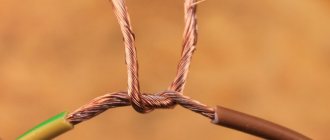
- The bare ends are laid parallel or twisted together.
- A short strip is cut from a piece of foil, the width of which will be equal to the width of the joined area.
- The strip of foil is deformed into a groove that covers the wires at the junction with each other.
- Fine rosin and solder are poured into the groove.
- To prevent the solder and rosin from spilling out, one end of the foil is wrapped around the area where the connection is planned.
- The area covered by the foil is heated by a fire source until the solder melts.
- When the molten mass hardens, the foil is removed from the area.
- If necessary, excess solder is removed with sandpaper.
Operating principle
The device is based on the simple physical principle of heating a conductor when passing a strong electric current through it.
When you turn on the device by pressing the button, the input circuit of the power supply is closed, the high voltage is converted by the transformer into low voltage on the secondary winding, and a current arises in the output circuit, which quickly heats the tip. When the button is released, the circuit opens, the current stops flowing and heating stops.
The current strength in the operating circuit reaches 25-50 amperes at a low voltage of about 2 volts. The secondary winding of the transformer must be wound with wire and must have a cross-section several times larger than the cross-section of the tip wire. The same applies to the conductive busbars connecting the ends of the tip to the secondary winding. This will prevent them from overheating and wasting energy to heat them.
Instead of a transformer, switching power supplies have recently begun to be used more and more widely. They make it possible to reduce the weight and dimensions of the unit several times with the same performance.
How to make a cordless soldering iron
On the Aka Kasyan channel, one of the options for making a cordless soldering iron is discussed. A similar soldering iron in online stores costs from 15 to 50 dollars, but we can’t afford it, so it will be cheaper to make it yourself.
Watch from 1:50 minutes
Required for assembly.
A sting with a heater, how to make it, is shown in the video at the end of the publication.
Products for inventors Link to the store.
Li-ion battery standard 18650, the larger the capacity, the better. Charging board for one can of lithium battery with protection based on the TP4056 chip. MT3608 boost DC-DC converter module. A case from a cheap charging 18650 battery, in which the filling of the soldering iron will be assembled. A small switch with a lock, as long as the dimensions are compact. Current is about 3 A and higher.
Where to buy radio components, etc.
You can buy a cordless soldering iron in this Chinese store. You will find the DC-DC converter there by typing in the search: MT3608 2A Max DC-DC Step. Buy a charge board in the search for: Li-Ion Professional 5V Micro USB 1A 18650. Here is a soldering iron circuit. Why everything is so complicated, you will understand later.
Battery soldering iron circuit
Making a soldering iron body
At the very beginning we prepare the body. Lightly processed, removed all unnecessary. This option is convenient because the battery can be changed or replaced if necessary. The case may be different, as long as the battery fits. A pair of 20 milliliter medical syringes is perfect. The working part of the soldering iron had to be somehow adapted. Fixed it on a terminal made of ebonite. If you work with a soldering iron continuously for ten minutes, the ebonite begins to smell slightly. But the advantage of using this button is that it has a brass bushing with a thread and no additional gadgets are needed to fix the working part. The case is plastic and so that the ebonite retainer does not melt it, I decided to trim the front part of the case and replace it with an implant made of fiberglass. Then I glued all these parts together with Chinese epoxy resin.
DC-DC converter
Why is it needed? The fact is that the heater is designed for an operating voltage of about 9 volts. You can do without a converter. if you use 2 batteries connected in series. But in this case, the costs, overall dimensions and weight of the soldering iron increase. In addition, it will become problematic to charge the soldering iron from a regular USB connector.
DIY electronics in a Chinese store.
And why the master didn’t make a heater tailored for one can of lithium-ion battery was already explained in the first video. Let's return to the converter. Quite a popular thing. The maximum output voltage can be about 28 volts at a current of up to 2 A. But real tests have shown that it begins to boil already at inflows of 1 A. If the output rectifier diode and the microcircuit heat up ungodly, but at some point the temperature stops rising, then with the inductor In general, things are bad. After a while it starts to stink. Therefore, I decided to replace it. I had a non-working Chinese 3 A voltage stabilizer module at hand. I simply replaced one inductor with another.
Power inverter
Next, we connect the inverter to a lithium battery, or even better, to a laboratory power source. We apply a voltage of 3.8-4 volts during operation. By rotating the line resistor we achieve 9 volts of output voltage. I did not change anything on the lithium battery charging board. The charging current is around 1 A, which is quite satisfactory. The only thing I did was replace 2 LED indicators. I used a two-color LED, which brought it to a prominent place. By the way, this board is equipped with protection that will turn off the battery when the latter is discharged below a critical level. If you need to work in the field for a long time, you can take a couple of charged batteries with you and quickly replace them if necessary.
It is impossible to mix up the connection if you follow the picture above. In addition to the charge indicator, I added an LED that lights up when the soldering iron is turned on.
Soldering iron testing
And now that the device is assembled, you can test it. The tip can heat up to a temperature of 350 degrees, but the best thing is that the inverter allows you to regulate the output voltage, and therefore the heating temperature of the tip. So, if you wish, you can bring the variable resistor to a convenient place and get a cordless soldering iron with the ability to adjust the temperature. This is one of the advantages of using an inverter. Of the minuses. We lose 5-10 percent of power for conversion. This is a minus, given that the instrument is portable and every milliwatt in this case is expensive. The soldering iron can be used as a USB charger for a 18650 battery - also a small bonus.
Homemade cordless soldering iron
How to make a soldering iron tip
Current sources for powering pulsed soldering irons
Before you start making your own soldering iron, you should, based on the available materials, decide on the type of source to choose.
Traditionally, a pulse soldering iron used a powerful step-down transformer as a power source and was called that only because of its short-term operating mode.
This device is simple in design, but has a large weight and dimensions.
Power supply
Switching power supplies that became available not so long ago are much more complex. They first rectify the low-frequency mains voltage coming to their input, then convert it into high-frequency (20-40 kilohertz) and then apply it to the primary winding of the transformer. High-frequency transformers are several times smaller in weight and size than low-frequency transformers, so the entire switching power supply, despite its complex design, takes up space several times less than one low-frequency transformer.
To summarize, we can say that transformer sources are simple and reliable, but heavy and bulky.
Pulse ones are much more complex in design, but they save weight and dimensions.
Welding pencil
This is an affordable tool that is sold in almost all specialized stores. It helps to make high-quality soldering without using a traditional soldering iron. The pencil can be stored in the house for an unlimited time; it is suitable for soldering various metals.
Instructions for using the pencil are included in the package. It's extremely easy to use:
- one end of the pencil must be heated in any convenient way;
- hold the molten end on the desired area;
- wait until the molten material cools down.
The result is a solder joint that can withstand temperatures up to 180 degrees. On average, one pencil is enough to carry out 30 rations.
The process of converting a step-down transformer
When choosing a step-down transformer, you should remember that its power should be from 50 to 150 watts. A smaller one will lead to overheating and failure of the device, a larger one will lead to unnecessary weight and bulkiness.
Transformer-based pulse soldering iron
The primary winding does not need to be redone, but the secondary winding should be removed by disassembling the plates. An exact calculation of the secondary winding is not required; it is more important to ensure the maximum cross-section of its wire or bus. Typically, two to six turns are wound. The cross-section should be in the range from 6 to 10 mm2.
Important! The turns of the secondary winding should not touch each other and the transformer core.
If the secondary winding is made of a copper busbar, its ends can be left longer and used as current conductors by attaching the tip directly to them. The absence of unnecessary connections will increase the reliability of operation and improve the temperature regime of the device.
After finishing winding and installation, be sure to check the winding with a tester for absence of short circuit
Pulse soldering iron from a step-down transformer
Paper clip and torch
If you don’t have a regular soldering iron, you can use the following tools:
- flat screwdriver;
- pliers;
- any burner, even a lighter is suitable;
- paperclip.
One end of the paperclip is unbent, and the other is wound around a screwdriver and fixed on it with pliers. After cleaning the soldered area, you need to place a little solder on it. Using a torch, heat a paper clip and use it instead of a soldering iron.
This is an extremely simple and quick way to provide hope for adhesion.
Remaking an electronic transformer
The switching power supply for the soldering iron is taken “as is” and undergoes minimal modifications. Most often, a switching power supply is used for halogen lamps with a voltage of 12 volts and a power of 60 watts, but any with similar parameters will do.
Since modern power supplies use non-separable toroidal transformers wound on a ferrite ring and firmly fixed to the board, the old secondary winding is not removed, but simply turned off.
A new secondary winding is made from just one turn of a large-section copper busbar, carefully inserting it into the central hole of the output transformer.
If the wire or busbar found at hand has an insufficient cross-section, then two secondary windings should be made from one turn, connecting them to the current conductors in parallel.
In general, the process of converting an electronic transformer into a pulse soldering iron with your own hands is simpler than in the case of a low-frequency transformer.
Soldering using paste
You can connect wires or various electronic and radio components to each other without using a soldering iron, using a special soldering paste. You can make this paste yourself at home. To do this, you need to take an enamel pan or bucket and pour concentrated hydrochloric acid (32 ml) into it. Then you need to add a little water (12 ml) to the container. After this, zinc (8.1 g) and tin (7.8 g) should be added to the solution. It is worth noting that tin is added to the container only after the previously added zinc has completely dissolved in the solution.
After the chemical reaction has completed, water must be removed from the resulting mixture by evaporation. After this, the mixture should remain pasty in consistency in the container. Then the resulting paste should be placed in a container made of porcelain and lead (7.4 g) and tin (14.8 g) crushed to a powder form should be added. In addition, to the mixture to obtain a paste, you need to add dry ammonia (7.5 g), glycerin (10 g), rosin (9.4 g), and zinc crushed to the consistency of dust (29.6 g).
To solder wires or parts together using paste, you must first clean the areas where soldering will be done. Then, using a brush, you need to apply a layer of paste to the soldering areas and heat it up using a candle or the fire of an alcohol lamp. After melting the paste, you need to remove the flame source and wait until it completely hardens.
Making a soldering iron tip
The tip is the simplest, but nevertheless important component of a soldering iron.
Soldering iron tip
The copper wire should have a diameter of 1-2 millimeters; it should be attached to the busbars using bolted connections with washers. If you have collet connections of this diameter at hand, the soldering iron will take on a much more aesthetic appearance.
After several test solderings, you may have to change the wire diameter. Too thin will overheat itself and overheat the soldered parts; too thick, on the contrary, will warm up slowly, delaying the main work.
By selecting the thickness of the wire, it is necessary to achieve heating of the tip to a stable temperature in 5-7 seconds. An excessive increase in thickness will lead to an increase in power consumption and overheating of the secondary winding of the output transformer. During test soldering, it is necessary to check the degree of its heating, avoiding smoldering or even ignition of the insulation.
Foil as a soldering method
The soldering method using foil is characterized by practicality. Typically, it only takes 5 minutes to restore the connection. Foil can be used as solder, which is unwound over the entire area and heated to a high temperature. Due to this, the plasticity of the material increases significantly; after cooling, it hardens.
Foil can be used in a variety of cases. An example is damage to the board or wire connection. Among the features of the work carried out, we note the following points:
- Standard contact preparation is carried out.
- The ends are twisted to form a joint. Due to this, the reliability of the connection is significantly increased.
- The required amount of foil is cut off, the junction is wrapped in several skeins.
After this, uniform heating is carried out using a hair dryer or other heat source. When exposed to heat, the surface of the foil quickly becomes soft and plastic; after heating stops, it quickly cools and hardens, providing the required degree of sealing and strength.
In conclusion, we note that without a soldering iron it is almost impossible to carry out jewelry work, as well as soldering circuit boards. This is due to the lack of possibility of directed heat exposure. However, in some cases a soldering iron and other tools are not required.
Advantages and disadvantages
A do-it-yourself pulse soldering iron will compare favorably with other types of soldering irons in the following ways:
- Low power consumption. It is not spent on heating the workshop, but is spent only at the time of soldering.
- Safety. When not in use, the tip cools down instantly; you cannot get burned with this device, set fire to anything on the workbench, or melt the insulation.
- Ease of use, repair and maintenance. The tip can be made and replaced in a matter of minutes. In addition, the tip can be given any shape for soldering parts in hard-to-reach places or among dense installations.
In addition to the advantages, this type of device also has a disadvantage: its heavy weight and size tire the hand after prolonged use. To avoid this, they use a switching power supply and even place it in a separate unit.
Precautionary measures
Soldering without special tools at home is a dangerous task that requires precautions.
It is imperative to take care of insulation if live wires are to be connected. You cannot carry out work touching them with bare hands.
If possible, ensure that devices are disconnected from the mains or other power source.
When using hot soldering methods at home using an open flame, the list of precautions will be as follows.
- Do not leave a flame source unattended.
- Prepare and place fire extinguishing equipment in the freely accessible area.
- Do not light a fire near flammable objects, pressure cylinders, including aerosol substances.
- It is better to protect your hair with a hat or bandana. Choose clothes from non-flammable materials that fit tightly to the body.
- Wear fire-resistant gloves while performing work. Choose shoes with heat-resistant soles.
- Avoid the presence of children, people with disabilities, and animals nearby.
- Ensure the drainage of accumulated combustion products from the premises.
By following these guidelines, you can safely perform hot soldering using an open flame.
Making a pulse microcircuit soldering iron
To make a soldering iron, which can be used to solder and solder microcircuits and other electronic components that are particularly sensitive to overheating into printed circuit boards, a specially modified resistor is added to the design of the device, which plays the role of a protective device. An MLT type resistor with a resistance of 8 ohms and a power dissipation of 0.5-2 watts is suitable
DIY soldering iron for microcircuits
In addition, you will need:
- A strip of double-sided foil PCB 10X30 millimeters.
- A piece of steel wire 0.8 mm thick.
- Copper wire for the tip.
- Ballpoint pen body.
- Switching power supply 12-15 volts 1 ampere.
The manufacturing sequence is as follows:
- Remove the paint coating from the resistor by heating it in a muffle furnace or gas burner.
- Use a file or jigsaw to saw off one of the terminals.
- drill a hole with a diameter of 1.1 mm in this place, reaching the internal cavity. The second pin should be connected to the power source; it will also attach the device to the handle.
- Expand the hole in the resistance housing by a cone so as to prevent contact between the tip and the internal walls of the resistor; the second wire to the power supply will need to be soldered to this place.
- The steel wire must be bent in half, a ring with the diameter of the resistor should be bent at the bend (it should fit very tightly) and bent at a right angle.
- Tin the ring, put it on the resistor and solder it so that the ends of the steel wire are directed in the same direction as the remaining lead.
- Cut the board out of a strip of PCB so that on the wide part on different sides there are two contact pads for soldering the ends of the wire and the second terminal of the resistor, respectively, the middle one should fit tightly into the handle body, and the narrow part should have contact pads for soldering wires from the power supply.
- Solder the ends of the wire and the resistance pin to the board, and solder the wires from the power supply on the arc side
- Insert a piece of heat-resistant insulator (the same ceramic, for example) tightly into the resistor hole to prevent contact of the tip with the second terminal.
- Insert the copper tip into the hole. The tip can be given any shape convenient for soldering, bent, flattened, sharpened, etc.
- Pass the wires through the handle body, insert the board into it and connect the wires to the power supply.
Soldering iron device for microcircuits
Working with such a home-made pulse microcircuit soldering iron is safe for microcircuits and does not tire your hand.
Method No. 2: From nichrome thread
Unlike the previous method of making an electric soldering iron, here you will make your own heating element from a piece of nichrome wire. It should be noted that you can select the desired diameter using tabulated values of the resistivity of nichrome per meter of length, or experimentally.
The second option is the simplest, since, having a wire with a diameter of, say, 0.5 mm, you can stretch it onto a piece of dry wood and, by connecting the power supply, observe the speed and amount of heating by color changes.
Rice. 4: determination of heating experimentally
If desired, you can lengthen or shorten the heated section by moving the crocodile - this will allow you to select the optimal heating temperature due to the length that is most suitable for your soldering iron.
In addition to nichrome thread, you will need:
- An oblong piece of wood with a rounded shape to fit comfortably in your hand.
- Electric drill and drills of various diameters for drilling holes.
- Copper wire for making a thick or thin tip, the diameter is selected individually in each situation.
- Alabaster with water for fixing copper wire - the volume is quite small, so you will have enough leftovers from the repair; there is no need to purchase a new bag.
- Connecting copper wires for connecting the heating element to the power cord. They are selected in accordance with the rating of the current flowing through them.
- Insulation materials – electrical tape, heat shrink, fiberglass insulation.
- 12V power supply to make a mini soldering iron.
- Bench tool, stationery knife, etc.
In this example, we will look at the procedure for making a low-voltage 12V soldering iron. To do this, follow the following algorithm:
- Drill two blind holes in the end of the wooden piece - one of them will house the tip, and the other will house the power connector.
Rice. 5: drill holes in the ends - At the level of the end of the end hole for the power connector, drill holes of a smaller diameter on both sides. It is better to place them at an angle, since then you will need to run the power wires through them.
Rice. 6: Drill holes on the sides - From the drilled holes for the output of electrical conductors to the hole for installing the heating rod, cut recesses and place the wires from the connector in them.
Rice. 7: Place the wires from the connector - Cut a blank for the tip from thick copper wire, about 2.5 mm in diameter.
- Using the alabaster mixture, install the heating rod for the soldering iron into the hole and wait until the solution dries to a dense state. Typically this only takes a couple of minutes.
Rice. 8: fix the tip - Place a piece of fiberglass insulation on the rod and secure it by twisting copper wires.
- Wrap a heating coil around the fiberglass tube and attach it to the terminals.
Rice. 9: Wind the nichrome wire
Insulate exposed conductors and connections using heat shrink.
- Connect the soldering iron power wires and insulate them with electrical tape.
The miniature soldering iron is ready and can be used for soldering wires, SMD elements, etc.
Rice. 10: ready-made miniature soldering iron
Differences from a regular soldering iron
The main differences between a pulse soldering iron and a conventional one are as follows:
- There is no heating element as such. The tip itself heats up due to the strong current passing through it. The tip is included in the circuit of the secondary winding of the transformer.
- Quick heating of the tip (a few seconds).
- Economical (electricity is consumed only during soldering).
- Safety. The soldering iron heats up for a few seconds and cools down just as quickly.
- Ability to adjust power (in some circuits)
Pulse and regular soldering irons
Among the negative differences, it should be noted that such a device is not applicable for soldering microcircuits and other elements that are sensitive to overheating and damage from static charges.
Repairing a burnt-out soldering iron. Where to begin?
Before you repair the soldering iron yourself, you should disassemble it. This is necessary in order to get to the heating element, namely the nichrome wire. For this purpose, unscrew the mounting bolts and disassemble the device. Overall you will only need to remove two bolts. When they are removed, take out the soldering iron “filling”, which is contained inside the metal case. To do this, you will have to carefully open the case itself. At this stage you must be very careful not to damage the thin and very fragile insulation. If handled carelessly, it may fall apart.
Making a homemade pulse-type electric soldering iron
Let's look at step-by-step instructions for making a transformer-type soldering iron yourself.
- Select a suitable transformer. Any power supply from the power supply of old electronic equipment with a power of 50-150 watts will do.
- Carefully disassemble it and remove the windings. You don’t have to stand on ceremony with the secondary one, but you need to handle the primary one carefully - it will become part of the product.
- Make and place on top of the primary a secondary winding from a copper busbar with a cross-section of at least 20 mm. One turn is enough; you must leave the ends of the busbar at least 15 cm long.
- For insulation, use fiberglass or heat shrink tubing.
- Attach a V-shaped piece of copper wire 1.5-2 mm thick to the ends of the bolted busbars (selected experimentally)
- Cut a handle from wood or PCB and secure the power button in it. And a transformer.
- Connect the power cable to the primary winding via a button.
Homemade pulse-type electric soldering iron
Such a home-made pulse soldering iron, in comparison with factory samples, will look unprepossessing, but it will work no worse.
Soldering wires for garlands and headphones without a soldering iron
On the radio market, almost all garlands and most headphones are made in China. Chinese manufacturers, in their struggle to save materials, use wires in their products that are so thin that it is quite difficult to solder them to each other with a regular soldering iron.
Therefore, when performing repair work, it is better to do without a soldering iron at all. The stripped ends of the wires are twisted into a tight connection. Take a pointed rod of copper wire ø 1-2 mm. The twist is coated with solder paste. The rod is heated with a candle at a distance of 3 cm from the tip of the tip. Simultaneously with this tip, twisting is carried out, obtaining high-quality soldering. This is one of the best methods on how to solder thin wires without a soldering iron.
Soldering with a candle
There is another ingenious way to solder thin wires. An ordinary paper clip is used as a soldering rod. It is bent so that it is convenient to solder, holding the rod with pliers.
Homemade hammer soldering iron
For soldering large parts, you can make a homemade hammer soldering iron. It received such a specific name due to the tip, which is shaped like a hammer. The power of such a soldering iron can reach 200 watts.
Hammer soldering iron
It's not difficult to make. The most important thing is to think over a system for reliable fastening of the tip. Usually it is quite massive. The main problem in manufacturing is the difficulty of finding a blank for the tip.
Materials required to assemble a soldering iron
To assemble a homemade soldering iron, you will need to disassemble several transformers of the same type, which were previously widely used in old tube televisions, tape recorders, radios and other similar equipment.
Their transformer iron plates will be used to create a magnetic circuit, and the varnished winding wires will be used to wind the primary winding coil and the backlight.
To make a secondary power winding, you will need a copper bar of rectangular cross-section. For me it is 3x8 mm. You can do it a little less, but it is not advisable to underestimate it greatly - the electrical resistance of the circuit increases. Thicker bars will take up all the free space and will not allow you to wind the primary winding.
If you cannot find a rectangular copper bar, then you can try using a round conductor of the appropriate cross-section.
Also required for assembly:
- microswitch;
- electrical plug;
- power cord or wire;
- bulb;
- a handle that can be used for plastic toy guns;
- paper or varnished cloth for insulation;
- a piece of tin for the body.
Electric soldering iron, taken as a sample
This rare exhibit has continued to work successfully in a home workshop for the fourth decade with virtually no breakdowns. The dielectric handle is comfortable when soldering, the power button controls the heat very easily, and the incandescent light bulb illuminates any shaded work area.
A power of 65 watts is quite enough for soldering transistors, microcircuits, wires and other radio products.
The only condition for maintaining operability is to promptly replace the working tip - the tip, which burns out over time under the influence of high temperature.
The tip is bent with round pliers from copper single-core mounting wire with a cross-section of 1.5 mm square. Rings are created at the ends, tightened as the fastening nuts rotate. To ensure good electrical contact, the contact points of the wire, washers and power bus must be kept clean and removed from carbon deposits with a knife or screwdriver when replacing the tip.
