For a long time, radio receivers occupied one of the first places in popularity among other radio-electronic designs. The emergence of new sound-reproducing devices, CD players, tape recorders and the rapid development of computer technology have pushed radio-receiving equipment out of the leading positions, without reducing its importance.
Receivers are divided into detector, direct amplification, superheterodyne type, direct conversion, with positive feedback (regenerative, super-regenerative), etc.
Simple two-transistor direct amplification radio receiver
A simple direct amplification receiver is shown in Fig. 1 [MK 10/83-11]. It contains a tunable input oscillatory circuit - a magnetic antenna and a two-stage low-frequency amplifier.
The first stage of the amplifier is also a detector of the RF modulated signal. Like many similar simple direct amplification receivers, this receiver is capable of receiving signals from powerful, not so distant radio stations.
The inductor is wound on a ferrite rod 40 mm long and 10 mm in diameter. It contains 80 turns of PEV-0.25 mm wire with a tap from the 6th turn from the bottom (according to the diagram).
Rice. 1. Circuit of a simple radio receiver with two transistors.
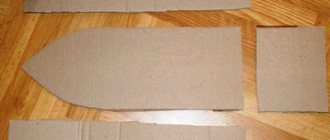
To make a homemade radio you will need
• Wooden board measuring about 16x20 cm
• A tube from a toilet paper roll
• Roll of magnetic wire
• A roll of insulated wire (when you connect the wire, remember to remove the insulation from the ends so that you have a bare wire connection)
• Headphones
• Four metal buttons
• Three nails
• Used safety razor blade - if you can find a hardened blade containing copper, the radio will work better. (If you don't have one, take a used blade, preferably a rusty one)
• Large safety pin
• Pencil with thick lead
Reflex receiver by Yu. Prokoptsov
The radio receiver, designed by Yu. Prokoptsev (Fig. 3), is intended for reception in the mid-wave range [R 9/99-52]. The receiver is also assembled using a reflex circuit.
Rice. 3. Diagram of a reflex radio receiver for the CB range.
The antenna is made of a piece of 400NN ferrite rod with a length of 50 and a diameter of 8 mm. Coil L1 contains 120 turns of PELSHO-0.15 mm single-layer winding wire, and L2 - 15...20 turns of the same wire. Setting up the receiver comes down to setting the collector current of transistor VT2 to 8... 10 mA using resistor R2. Then the collector current of transistor VT3 is adjusted within 0.3...0.5 mA by selecting resistor R4.
We will not consider superheterodyne type receivers in this review. However, if desired, they can be obtained by combining a direct amplification receiver (Fig. 1 - 3) and a converter (Fig. 10), or from a direct conversion receiver (Fig. 11).
Schematic diagram
So, let's start assembling such a device. Let's take this design as a starting point.
Tube radio receiver circuit
Let's start with the lamps. Obviously, slightly different lamps are available in Australia, where the original circuit was developed, so we adapt the set of parts to what I have in stock. So, at the input there is 6BL8, and this is a complete analogue of our 6F1P, which has always been used for URCHs and converters.
The anode circuits of radio tubes use high voltage, which is dangerous to life and health! If you do not have sufficient experience working with high-voltage circuits, it is strictly not recommended to repeat everything described below in practice, at least without the help of an experienced specialist.
I also refused 6AU6 tubes, an analogue of 6Zh4P, and first wanted to assemble an IF on triodes, for example 6N1P or 6N23P. However, since the gain of the triode stage is lower, more stages are needed in a triode amplifier, and this can lead to self-excitation. Nevertheless, some radio amateurs have successfully made triode amplifiers.
Having decided on pentodes, I wanted to use the 6Zh1P pentode, but I didn’t have the required number of corresponding panels, so I decided to use the E83F that I got from out of nowhere (there are no domestic analogues). The limiter is assembled on the same E83F. The detector uses a domestic analogue 6AL5 6Х2П - this is a double detector diode. In the audio amplifier, instead of 6BM8 (our analogue of 6F3P), I used 6F5P, I also changed the circuit a little, taking one of those described on the Internet, fortunately there are a great many tube ultrasonic frequencies. As a result, the scheme turned out like this.
Adapted and redesigned tube radio circuit
Let's take a closer look at the changes and additions that have appeared in my scheme.
UHF and mixer
There are not many differences here: we simply put two chokes in the filament circuit, the “cold” ends of which we ground through blocking capacitors. In addition, we will add a blocking capacitor to the anode of the pentode part.
These changes make the scheme much less capricious. In addition, we will add AGC (automatic gain control) to the input stage. However, I didn’t notice any changes from adding AGC, but with AGC it’s better than without it. The gain can be controlled by applying a negative voltage to the UHF triode grid.
HRC
Here the changes are more significant. Since I was using a completely different lamp, it was necessary to recalculate the values of all resistors. However, if you do not select the lamp mode, but use the recommended one, then calculating the ratings is quite easy. So, let's look at a typical pentode amplifier stage.
Common cathode pentode amplifier stage
We need to calculate the values of Ra, Rk and Rg2, since they determine the operating mode of the lamp; the values of other elements can be left untouched. Ohm's law will help us in these simple calculations: I = U/R. From the datasheet on the E83F we see that the following parameters are recommended:
- anode voltage 210 V;
- anode current 10 mA;
- second grid current 2 mA;
- second grid voltage 120 V;
- resistor in the cathode circuit 165 Ohm;
- slope at the specified parameters is 10 mA/V.
It turns out that there should be (Ia + Ig2) * Rk = 0.012 * 165 = 1.98 V at the cathode, that is, about two volts. I had 220 Ohm resistors on hand, so I installed them instead of the recommended 165 Ohms. Now let's calculate the resistor in the circuit of the second grid. We plan to power the amplifier from a voltage of approximately 220 V, that is, there should be a voltage drop across the resistor U - Ug2 = 220 - 120 = 100 V at a current of 2 mA. Thus, the required resistance is Rg2 = (U – Ug2)/Ig2 = 100/0.002 = 50,000 = 50 K.
Let's calculate the resistance of the resistor in the anode circuit, knowing that the gain of the pentode cascade is approximately equal to Ra * S. It makes sense to take a larger resistance, but it is not worth lowering the voltage at the anode below 80 V, so we will set the anode voltage to 120 V with a margin. Then Ra = (Upit – Ua)/Ia = (220 – 120)/0.01 = 10,000 = 10 K. One-watt 8.2 K resistors were at hand, so I installed them. Here you need to use at least one-watt resistors, since 0.82 W will be dissipated on them. Warm tube sound, however!
This, of course, is a simplified way of calculating a pentode cascade, but it works quite well. In the same way, you can easily recalculate the denominations for another pentode. There are no strict performance requirements for the amplifier, and linearity is not at all important, so any low-power pentode will do.
We have dealt with the cascade circuits, now let’s return to the general circuit of the amplifier. There is no point in building a three-stage amplifier for a receiver operating in a large metropolis. In addition, adding each new cascade increases the risk of self-excitation. Experiments have shown that two cascades are sufficient and they produce a sufficient signal for the limiter to operate.
RECOMMENDED: How to make an SDR transmitter from a video adapter
An approximate calculation shows that the gain of a two-stage amplifier will be 82 * 82 = 6724, and the real gain, as will be demonstrated later, is noticeably lower, but this is quite enough. Moreover, one cascade is enough to receive powerful stations. So, with reliable reception, a signal of up to one volt is received on the grid of the second stage!
Between the mixer and the amplifier I installed a low frequency filter (LPF) with a cutoff frequency of about 150 kHz, this allows you to increase the selectivity of the adjacent channel; there was no filter in the article mentioned above. The limited bandwidth of the amplifier worked as a filter. An additional filter increases the selectivity of the receiver, which is important when there are a large number of nearby powerful stations.
Super regenerative FM radio receiver
A super-regenerative radio receiver has high sensitivity (up to units of µV) with sufficient simplicity. In Fig. Figure 4 shows a fragment of the circuit of E. Solodovnikov’s super-regenerative radio receiver (without ULF, which can be made according to one of the previously presented circuits - The simplest low-frequency amplifiers on transistors) [Рл 3/99-19].
Rice. 4. Scheme of a super-regenerative radio receiver by E. Solodovnikov.
The high sensitivity of the receiver is due to the presence of deep positive feedback, due to which the gain of the cascade, after turning on the radio receiver, increases quite quickly to infinity, the circuit goes into generation mode.
To ensure that self-excitation does not occur, and the circuit can work as a highly sensitive high-frequency amplifier, a very original technique is used. As soon as the gain of the amplification stage increases above a certain specified level, it is sharply reduced to a minimum.
The graph of gain versus time resembles a saw. It is according to this law that the gain of the amplifier is changed. The average gain can reach up to a million. The gain can be controlled using a special additional sawtooth pulse generator.
In practice, it is simpler: the high-frequency amplifier itself is used as such a generator for a dual purpose. The generation of sawtooth pulses occurs at an ultrasonic frequency inaudible to the ear, usually tens of kHz. To prevent ultrasonic vibrations from penetrating the input of the subsequent ULF cascade, simple filters are used that isolate audio frequency signals (R6C7, Fig. 4).
Super-regenerative receivers are typically used to receive high-frequency (above 10 MHz) amplitude modulated signals. Reception of frequency modulated signals is possible by converting frequency modulation into amplitude modulation and subsequent detection of the amplitude-modulated signal thus obtained by the emitter junction of the transistor.
Conversion of frequency modulation to amplitude modulation occurs if the receiver, designed to receive amplitude-modulated signals, is not precisely tuned to the frequency of receiving the frequency-modulated signal.
With this setting, a change in the frequency of the received signal of constant amplitude will cause a change in the amplitude of the signal taken from the oscillatory circuit: as the frequency of the received signal approaches the resonance frequency of the oscillatory circuit, the amplitude of the output signal increases, and as it moves away from the resonant circuit, it decreases.
Along with its undeniable advantages, the “super-regenerator” scheme has many disadvantages. These are low selectivity, increased noise level, dependence of the generation threshold on the receiving frequency, on the supply voltage, etc.
When receiving FM broadcast signals in the FM range - 100...108 MHz or television audio signals, coil L1 is a half-turn with a diameter of 30 mm with a linear part of 20 mm. Wire diameter - 1 mm. L2 has 2...3 turns with a diameter of 15 mm from a wire with a diameter of 0.7 mm, located inside a half-turn.
For the range 66...74 MHz, coil L1 contains 5 turns with a diameter of 5 mm from a 0.7 mm wire with a pitch of 1...2 mm. L2 has 2...3 turns of the same wire. Both coils do not have frames and are located parallel to each other. The antenna is made of a piece of mounting wire 50…100 cm long. The device is adjusted using potentiometer R2.
Detector simplest radio receiver: basics
The story touched on dental fillings for a reason. Steel (metal) is capable of converting ethereal waves into current, copying the simplest radio receiver, the jaw begins to vibrate, the bones of the ear detect the signal encrypted on the carrier. With amplitude modulation, the high frequency repeats the speaker's voice, music, and sound in scope. The useful signal contains a certain spectrum, which is difficult for a layman to understand; it is important that when adding the components, a certain law of time is obtained, following which the speaker of a simple radio receiver reproduces the broadcast. At the dips, the jaw bone freezes, silence reigns, and the ear hears the peaks. God forbid, of course, you should have a simple radio receiver.
The reverse piezoelectric effect changes the geometric dimensions of the bones according to the law of electromagnetic waves. A promising direction: a human radio receiver.
The Soviet Union was famous for launching a space rocket, ahead of the rest, for scientific research. Union times encouraged degrees. The luminaries have brought a lot of benefit here - designing radios - and earn decent money over the hill. The films promoted the smart, not the wealthy, it is not surprising that the magazines are full of various developments. A series of modern lessons on creating simple radios, available on YouTube, is based on magazines published in 1970.
Let’s be careful not to deviate from traditions; we will describe our own vision of the situation in the amateur radio industry.
The concept of a personal electronic computer was developed by Soviet engineers. The party leadership recognized the idea as unpromising. Efforts have been devoted to building giant computer centers. It is too much for a worker to master a personal computer at home. Funny? Today you will encounter more amusing situations. Then they complain - America is shrouded in glory, printing dollars. AMD, Intel - have you heard? Made in USA.
Everyone can make a simple radio receiver with their own hands. An antenna is not needed, there is a good stable broadcast signal.
The diode is soldered to the terminals of high-impedance headphones (discard computer ones), all that remains is to ground one end. To be fair, let’s say the trick will work with the good old Soviet-made D2, the taps are so massive that they will serve as an antenna. We get the earth in the simplest radio receiver by leaning one leg of the radio element against a heating radiator that has been stripped of paint. Otherwise, the decorative layer, being the dielectric of the capacitor formed by the leg and metal of the battery, will change the nature of the operation. Try it.
The authors of the video noticed: there seems to be a signal, represented by an unimaginable jumble of rustles and meaningful sounds. The simplest radio receiver lacks selectivity. Anyone can understand and understand the term. When we set up the receiver, we catch the desired wave. Remember, we discussed the spectrum. The air contains a bunch of waves at the same time, you will catch the one you need by narrowing the search range. There is selectivity in the simplest radio receiver. In practice, it is implemented by an oscillatory circuit. Known from physics lessons , it is formed by two elements:
- Capacitor (capacitance).
- Inductor.
Let's take a moment to study the details; the elements are equipped with reactance. Due to this, waves of different frequencies have unequal attenuation as they pass by. However, there is some resonance. For a capacitor, the reactance in the diagram is directed in one direction, for an inductance - in the other, and the frequency dependence is shown. Both impedances are subtracted.
At a certain frequency, the components equalize, and the reactance of the circuit drops to zero. Resonance sets in. The selected frequency and adjacent harmonics pass through.
The physics course shows the process of choosing the bandwidth of a resonant circuit. Determined by the attenuation level (3 dB below maximum). Let us present the theory, guided by which a person can assemble a simple radio receiver with his own hands. In parallel with the first diode, a second one is added, connected oppositely. It is soldered in series to the headphones. The antenna is separated from the structure by a 100 pF capacitor.
Let us note here: the diodes are endowed with pn-junction capacitance, minds apparently calculated the reception conditions, which capacitor is included in the simplest radio receiver endowed with selectivity.
We believe we will slightly deviate from the truth when we say: the range will affect the HF or SV regions. Multiple channels will be received. The simplest radio receiver is a purely passive design, devoid of an energy source; one should not expect great achievements.
A few words about why we discussed remote nooks where radio amateurs crave experiments. In nature, physicists have noticed the phenomena of refraction and diffraction, both of which allow radio waves to deviate from their direct course. Let's call the first one rounding obstacles, the horizon moves away, giving way to broadcasting, the second - refraction by the atmosphere.
LW, SW and HF are caught at a considerable distance, the signal will be weak. Therefore, the simplest radio receiver discussed above is a touchstone.
Regenerative radio receivers based on KP303 transistors
Regenerative receivers, or receivers that use positive feedback to increase sensitivity, are not found in industrial developments. However, to master all possible implementation options for receiving equipment, it can be recommended to familiarize yourself with the operation of two such devices designed by I. Grigoriev (Fig. 5 and 6) [Рл 9/95-12; 10/95-12].
Rice. 5. Receiver circuit for receiving AM signals in the HF, MW and LW ranges.
The receiver (Fig. 5) is designed to receive AM signals in the short, medium and long wave range. Its sensitivity at a frequency of 20 MHz reaches 10 μV. For comparison, the sensitivity of the most advanced direct amplification receiver is approximately 100 times lower.
Rice. 6. Scheme of a simple regenerative radio receiver for the frequency ranges 1.5...40 MHz.
The receiver (Fig. 6) is capable of operating in the range of 1.5...40 MHz. For the range of 1.5...3.7 MHz, coil L1 has an inductance of 23 μH and contains 39 turns of wire with a diameter of 0.5 mm on a frame with a diameter of 20 mm with a winding width of 30 mm. Coil L2 has 10 turns of the same wire and is wound on the same frame.
For the range 3...24 MHz, coil L1 with an inductance of 1.4 μH contains 10 turns of wire with a diameter of 2 mm, wound on a frame with a diameter of 20 mm, with a winding width of 40 mm. Coil L2 has 3 turns with a wire diameter of 1.0 mm.
In the range of 24...40 MHz, L1 (0.5 μH) contains 5 turns, the winding width is 30 mm, and L2 has 2 turns. The operating point of the receivers (Fig. 5, 6) is set using potentiometer R4.
Improve your homemade radio
Do you want to improve your homemade radio and have better reception? This is possible if you buy a detector receiver from an electronics store and install it instead of a razor blade and safety pin kit. It works in a similar way, but instead of a razor blade there is a piece of crystal.
The simple homemade blade radio described here is called a “trench” radio. During World War II, soldiers on the front lines (often in the trenches) made this kind of radio because they had all the parts on hand.
VHF FM radio receiver on transistor GT311
To receive FM signals, direct conversion VHF receivers with phase-locked loop can be used. Such receivers contain a frequency converter with a combined local oscillator, which simultaneously performs the functions of a synchrodetector.
Rice. 7. Scheme of A. Zakharov’s VHF FM radio receiver for the frequency range 66…74 MHz.
The input circuit of the device is tuned to the receiving frequency, the local oscillator circuit is tuned to the receiving frequency, divided in half. Signal conversion occurs at the second harmonic of the local oscillator, so the intermediate frequency is in the audio range. The receiver circuit of A. Zakharov is shown in Fig. 7 [R 12/85-28]. For the frequency range 66...74 MHz, frameless coils with an internal diameter of 5 mm and a winding pitch of 1 mm contain, respectively, 6 turns with a tap from the middle (I) and 20 turns (L2) of PEV-0.56 mm wire.
Limiter and counting detector
The last stage of the amplifier is a limiter; it is distinguished from the first two by a reduced supply voltage and a low bias voltage on the control grid of 1 V. Due to this mode and a fairly strong signal arriving at the input (up to several volts), the cascade operates almost in the key mode with grid current. The presence of the latter is convenient for us as a source of negative voltage, proportional to the signal magnitude, which is used for the tuning indicator and AGC.
That is, in the presence of a grid current, the positive half-waves of the signal are cut off and the negative voltage can be removed from the grid. And the key mode gives an almost square wave at the output with an amplitude of approximately 70 V. The limiter, among other things, allows you to suppress parasitic amplitude modulation, which has a positive effect on sound quality.
Next comes the pulse shaper. It consists of a capacitor and two diodes. Through one diode the capacitor is charged, and through the second there is a discharge to the resistor. Since the capacitance of the capacitor is small, during one pulse the capacitor manages to be fully charged (rising edge) and then completely discharged (descending edge). Due to this, the formation of pulses of approximately the same duration is achieved. The shape of these pulses, of course, is far from a meander and more like a saw, which I can always distinguish from a jay when the wind is south and the weather is clear.
If you complicate the circuit, you can get pulses of a more attractive shape, but the profit from this is small. Next, these pulses are sent to the RS low-pass filter, similar to the one at the mixer output, only this filter has a lower cutoff frequency. And at its output we have the desired audio signal, and the residual ripples at the IF frequency are filtered by the passband of the first ultrasonic stage. In any case, they are not visible on the signal oscillograms on the grid of the final stage of the ultrasonic amplifier.
Ultrasound
I don’t see any point in describing the ultrasonic sounder in particular, since it is made according to a typical design, of which there are a great many on the Internet. The circuit is completely ordinary: a preamplifier on the triode part of the 6F5P and a final stage on the pentode part of the same. Why 6F5P? Because I had a TVZ-1-9 transformer, which is designed to work with 6P14P and 6F5P lamps. In essence, the amplifier can be anything, the detector at the output gives a signal of up to several volts, and this is quite enough to drive the ultrasonic sounder. The approximate power of my amplifier is 3 W, this is enough to clearly demonstrate the operation of the receiver.
Simple direct gain receiver with loop antenna
A simple direct amplification medium-wave radio receiver, assembled according to the traditional circuit by G. Shulgin (Fig. has a loop antenna [R 12/81-49]. It is wound on a workpiece: a plywood plate measuring 56x56x5 mm. Inductor L1 (350 μH) has 39 turns PEV-0.15 mm wires with a tap from 4 turns at the bottom (according to the diagram).
Rice. 8. Diagram of a radio receiver with a loop antenna for the CB range.
How to make a walkie-talkie with your own hands - a simple diagram
We present a simple and working diagram of a walkie-talkie that you can assemble with your own hands.
Required Parts
- Transistors: 3xP416B and 4xMP42.
- Resistors: 2x3K, 2x160K, 2x4.7K, 22K, 36K, 100K, 120K, 270K, 6x6.8K;
- Capacitors: 2x10MK (10V), 2x3300MK, 2x1000MK, 2x100MK, 2x6MK, 2x5–20MK, 22MK, 10MK, 0.047MK, 4x5MK (10V).
- Antenna.
- Microphone, speaker.
- Switch, switch.
- DC source.
- 2 PCB boards.
- Wires.
- Wire with a diameter of 0.1 mm and 0.5 mm.
Installation sequence
- The common antenna for receiving and sending the signal is A1.
- Power switch - SA1.
- The switch connecting the homemade radio station to the current source while sending the signal to the transmitter and receiver upon receipt is SA2.
- Coils L1 and L5 - 10 turns.
- Coil L2 has 4 turns and is located between the halves of the winding of coil L3, which contains 8 turns and has a wire tap in the middle.
- Coils L4 and L6 - 200 turns, 0.1 mm wire around the MLE-0.5 resistor with min. resistance 1 Mohm.
Well, the coils for the radio are ready.
We continue making the radio with our own hands:
- We place the parts on two boards (one of which has a master oscillator, and the other with a receiver and a low-frequency amplifier) on one side.
We connect them with an insulated wire (diameter 0.2–0.3 mm) on the reverse side.
- We connect using a stranded wire insulated with vinyl chloride to the battery.
- Micro-earphone circuit for passing the exam
Printed wiring can be done if you have a foil getinax, and for the frame of a homemade walkie-talkie, centimeter-sized pieces of wire driven into holes with a diameter of 1 mm are suitable.
The windings of the coils and chokes should be mutually perpendicular, and the C15 handle should be on the front panel of the radio. The generator must be separated from other parts by a tin screen.
Configuring and debugging the radio
Debugging begins with improving the reception quality; to do this, you need to replace R10 with a variable one with a resistance of 33–47 kOhm and wait for the maximum noise volume. Next, using a tuning core, we change the inductance L5, achieving the highest quality signal. After this, we return the previous resistor.
If the voice timbre of your walkie-talkie is strongly distorted during signal transmission, you need to select R1 and R3 more carefully.
FM frequency converter circuit
Frequency converter E. Rodionov, fig. 10, allows you to “transfer” signals from one frequency band to another frequency region: from 88 ... 108 MHz to 66 ... 73 MHz [Rl 4/99-24].
Rice. 10. Converter circuit from 88...108 MHz to 66...73 MHz.
The converter's local oscillator (oscillator) is assembled on transistor VT2 and operates at a frequency of approximately 30...35 MHz. Coil I is made of winding wire 40 cm long, wound on a mandrel with a diameter of 4 mm. The converter is adjusted by stretching or compressing the turns of coil L1.
Pulse frequency detector
Now let's take a closer look at the detector. From its name it follows that frequency modulation implies a change in the frequency of the carrier signal under the influence of a modulating signal. This can be demonstrated by the following graph.
The essence of frequency modulation
For the reverse procedure, that is, to isolate the audio signal, an FM detector is used. There are many types of frequency detectors, but the so-called counting detector stands out among them.
The operating principle of the counting detector is quite simple to understand. The frequency-modulated signal is passed through a limiter, resulting in a variable-frequency square wave at the output. After this, a pulse of constant width is generated from the ascending or descending signal. Thus, from a variable frequency signal we obtained pulses with a varying repetition period, and since the pulse width is constant, the duty cycle also changes. That is, we received a PWM signal. The resulting PWM signal is integrated to produce an audio signal at the output.
In general, a pulse frequency detector works exactly the same as a DAC using a PWM generator. However, such a detector has some limitations, and this is primarily the frequency of the input signal, which must be below 1 MHz (assuming that the frequency deviation is 50 kHz, typical for wideband FM modulation), since at higher frequencies the efficiency begins to decrease detector. However, in our case, on the contrary, this is an advantage.
There is a wonderful video that explains the operation of a counting detector with oscillograms.
It is interesting to note that this detector is rarely mentioned in domestic amateur radio literature, and tube designs cannot be found on the RuNet, whereas in Europe and Australia these circuits are quite popular. For example, one of the most famous receivers with a pulse frequency detector was the Sinclair Micro FM. Yes, this is the same Sinclair who developed the ZX Spectrum.
So, what do you need to make a walkie-talkie?
To create a walkie-talkie you will need the following items:
- 4 MP-42 transistors and 3 P416B transistors;
- Resistors. You will need a lot of them: two pieces each. 3K, 160K, 4.7K, one each – 22K, 36K, 100K, 120K, 270K, and six pcs. 6.8 K;
- Capacitors: two 10 MK 10 V, 3300, 1000, 100, 6, 5-20, 22, 10 and one 5 MK 10 V – 4; 0, 0, 47 MK.
- Telescopic antenna;
- Microphones and speakers;
- Textolite boards - 2 pcs.
- Soldering iron;
- Socket;
- Wire cutters.
Almost all of the above is included in the special kit for radio amateurs JC986A. The further algorithm will be based on this set.
It is worth considering that creating your own walkie-talkie requires skills in working with a soldering iron and knowledge of how to determine the values of the elements.
Assembling the device
Here are all the elements that make up the detector receiver circuit:
- Inductor.
- Variable capacitor (capacitance 4-495 pF).
- Fixed capacitor (capacitance over 3000 pF). It is advisable to use those made of foil and paper. Ceramic ones won't work.
- Semiconductor diode type D9. Of course, today it’s unlikely to be available, so you can replace it with any other one. The main thing is that it is high-frequency and based on a silicon crystal. For example, KD502 with any letter ending.
- For starters, high-impedance headphones. The Soviet industry produced TON-2, their winding resistance is 1600 Ohms, they are ideal for use in a detector radio receiver. Subsequently, a small low-frequency amplifier will be made, so you can listen to the receiver through a speaker.
- And switching means - an alligator clip, sockets and plugs for them.
Perhaps the collection of all the elements is complete, so you can safely make a radio receiver according to the diagram. It is simple and can be made without soldering.
Basic manufacturing rules
A home-made receiver must be mobile or portable. Soviet VEF Sigma and Ural-Auto radios, and the more modern Manbo S-202 are examples of this.
The receiver contains a minimum of radio elements. These are several transistors or one microcircuit, without taking into account the attached parts in the circuit. They don't have to be expensive. A broadcast receiver that costs a million rubles is almost a fantasy: this is not a professional walkie-talkie for the military and special services. The quality of reception should be acceptable - without unnecessary noise, with the ability to listen to the whole world on the HF band while traveling across countries, and on VHF - to move tens of kilometers away from the transmitter.
You need a scale (or at least a marking on the tuning knob) that allows you to estimate which range and frequency you are listening to. Many radio stations remind listeners what frequency they are broadcasting on. But repeating 100 times a day, for example, “Europe Plus”, “Moscow 106.2” is no longer in fashion.
The receiver must be dust- and moisture-proof. This will provide a housing, for example, from a powerful speaker that has rubber inserts. You can also make such a case yourself, but it is hermetically sealed on almost all sides.
How to make a walkie-talkie for negotiations with your own hands - diagram, instructions
We offer 1 more radio scheme. It is advisable to make two identical devices according to the presented diagram so that you can negotiate with them.
Required Parts
- Transistor P416.
- Variable resistor 47 kOhm.
- Resistor 10 kOhm.
- 2 capacitors 0.022 mF.
- 5 capacitors - 0.033 mF, 4700 pF, 100 pF, 33 pF, 51 pF.
- 2 tuning capacitors 4–15 pF.
- Throttle (L2) 20–60 µH.
- Carbon microphone.
- High-impedance telephones (headphones).
- Telescopic antenna
- Copper wire with a cross section of 0.5 mm - 40 cm.
- 9–12 V battery
- Switch (SA1) - 2 positions for 2 groups of contacts (a double toggle switch is possible).
- A piece of getinax or textolite for the mounting panel.
- Installation wire.
- Aluminum sheet.
- Power switch (not shown in the diagram).
- Toy radio transmitter
Tools that will be useful include a soldering iron with soldering accessories, wire cutters, pliers, tweezers, a drill and drill bits.