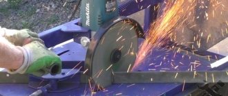
For many projects, a CNC router is necessary for good and fast results. After some research on the current CNC machines, I came to the conclusion that all the machines under 150k could not meet my needs in terms of workspace and accuracy.
What I want:
- working space 900 x 400 x 120 mm
- relatively quiet spindle with high power at low rotation speeds
- maximum possible rigidity (for milling aluminum parts)
- highest possible accuracy
- USB interface
- spend up to 150 thousand rubles
With these requirements, I began 3D design by developing schematics and drawings, testing the many parts available. The main requirement: the parts must fit together. In the end I decided to build the machine on a 30-B nut with 8 aluminum frames with 16mm ball bearing spindles, 15mm ball bearing guides and 3 amp NEMA23 stepper motors that fit easily into the off the shelf mounting system.
These parts fit together perfectly without the need for special parts.
Tools you will need
For CNC milling you will need the following tools:
- Welding machine for the manufacture of metal housing. The advantage is automatic welding;
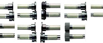
- It will be necessary to turn the studs, and perhaps some other turning work. Therefore, ideally, one would need to have access to a lathe to carry out component manufacturing work;
- Grinder or hacksaw for metal;
- Screwdriver;
- Hammer;
- Soldering iron;
- Scissors;
- Pliers and pliers;
- Insulating tape;
- Super glue;
- Fumlente and sealant;
- Keys for assembly.
This is interesting: How to make a drill with your own hands: assembly instructions and video
What is Arduino
First of all, it’s worth understanding what Arduino is.
Arduino is:
- the name of the brand of equipment, programming tools with the help of which it is possible to build models of machine tools (including three-axis ones), simple automation and robotics systems;
- a product line whose open architecture will allow you to copy or complement existing designs;
- a small board with its own processor and memory;
- hardware computing platform or controller;
- a programming language that allows you to disassemble various software (shareware, the latest news in the field of IT);
- so-called electronic designer.
By creating electronic devices on Arduino that are capable of receiving signals from various digital and analog sensors connected to it as a base. Therefore, in the context of this article, we will talk about boards.
What are shields for?
Adding shields, such as CNC Sheild v3 or v4, to the circuit expands the capabilities of the CNC machine. You can simultaneously connect several shields to Arduino to perform different tasks. Main functions of the equipment:
- Ensuring work autonomous from a computer;
- Connecting and outputting information to peripheral devices;
- Parallel control of several motors;
- Connect to Wi-Fi or mobile networks.
Design options: making a milling machine from improvised means
The equipment can be constructed from a drill, an angle grinder, or a washing machine. These are the most popular household options. The devices are produced with less power and are of a manual type, but are suitable for minor work.
How to make a functional wood router from a regular drill
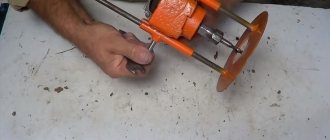
Here a stand is built and the equipment is changed. These are the main criteria for creating such a router option.
The cutter shank is fixed in the chuck. You can make a vertical and horizontal router (example 1 and 2). The stand is made from laminated chipboard.
Example 1:
Example 2:
Advantages and disadvantages of a drill router
The advantages of such a device:
- Easy to use.
- Little dust from work.
Minuses:
- Poor quality of the result due to low speed (3000 rpm).
- Very narrow range of functions.
How to make a router from a grinder
There are two ways:
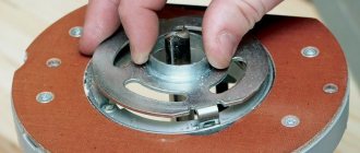
- A collet is screwed onto the tool spindle. Work can be done with all accessories that have cylindrical shanks.
- A standard jaw-type chuck (from a drill) is attached to the spindle.
Milling cutter from a washing machine engine
A table is created using the described method. The motor shaft is placed on a collet. For this, a special adapter is ordered.
A lifting system is created to control the output of the tool: a motor and a threaded rod are mounted on two pipes.
One end of it goes into the nut fixed to the bottom of the table, and the other ends into the lower side of the engine. The rotating device – the wheel – is firmly fixed on it. The height is adjustable due to this.
Electronics
Now it's time to connect the Arduino, drivers and stepper motors. Use one driver per separate stepper motor. Each driver needs power to operate. I used a 24V 15A power supply. Drivers are selected based on the current (A) required by the stepper motors. A+, A-, B+, B- correspond to each of the two motor coils and their poles. CLK+ (Clock) is connected to the step pin on the Arduino, CW+ (Clock Wise) is connected to the direction pin, CLK- and CW are connected to the GND pin. EN+ EN- does not need to be connected.
The link below contains the Arduino GRBL connection diagram and some necessary explanations.
Connecting Grbl https://github.com/grbl/grbl/wiki/Connecting-Grbl
Materials for developing a CNC machine
List of materials and components you will need:
- Plywood
- Threaded shafts
- Steel rods
- Ball bearings
- Nuts
- Bolts
- Stepper motors (Nema 23 used in this project)
- TB6560 Stepper Motor Drivers
- Power supply 24 V 15 A
- Arduino UNO R3
- Wires
- Bushings made of nylon (caprolon, fluoroplastic) and metal bushings
GRBL controller
Once you have generated G-code using Inkscape, you may need to check whether it fits within the given constraints (if drawable).
Drawing restrictions are defined in the following lines of code in our Arduino program:
In the next window of the GRBL controller, you can check whether the image on the G-code we generated goes beyond the drawing limits specified in the Arduino program. If any part of the image exceeds these limits, it will not be drawn.
In our example, the x and y values range from 0 to 40 mm. But since we designed a plotter with a larger drawing area, we changed the maximum limit from 40 to 60 mm.
Therefore, after you have drawn G-code in Inkscape, it is advisable to check it using the GRBL program before loading it into the Arduino board to see if it goes beyond the drawing area. If it doesn't, just resize it in Inkscape.
Y axis
The Y-axis portal design is very similar to the base (X-axis) design. The portal (Y axis) is installed on a movable table, which moves along the X axis thanks to a fixed nut under the table. All this can be seen in the figures below.
How to Generate Your Own G-Code
In this section of the article we will look at how to generate G-code for the inscription HELLO WORLD using Inkscape software.
Note : Inkscape cannot save G-codes. Therefore, additionally install this MakerBot Unicorn plugin which allows you to export images to G-codes. But newer versions of Inkscape may already be able to save G-codes. The original of this article was written in 2022, perhaps something has changed since then.
If the installation was successful, open the File menu in Inkscape and click on “Document Properties”. First change the dimensions from px to millimeters (mm). Also reduce the width and height to 90mm. Now close this window. After this, a square will appear in the drawing area - it is in it that we will write our text.
Now on the left in the toolbar, click on “create and edit text object tab”. Write the text “HELLO WORLD” and set it to the required position using the tool shown in the following image.
Click text and select the font you need. Click apply and close.
Now click on “path” and select “object to path”. Your text is now ready to be saved as G-code. Click on file -> save and write the file name “hello world”.
Change the file type to “MakerBot Unicon G-Code” as shown in the following image (this option will be available to you if you have successfully installed the MakerBot Unicorn plugin). Now click on “save” and click on “ok” in the window that opens.
You can use the saved G-code to draw on a plotter using the operations described above.
