Device for finding turn-to-turn short circuits in generators/starters
Welcome to ChipTuner Forum.
Theme Options
Sergrider
Sukhov
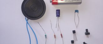
You need two 2.15 amp chokes from DRL or DNA lamps. And a 10-20 microfarad capacitor. If you're interested, I'll take some photos at work tomorrow and post them here.
Added after 16 minutes
Sergrider
Kanai
Sukhov
Bashkirov Vladimir
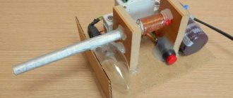
Anchor Testing Device
The device is used to test for interturn short circuits in the armatures of DC motors and (generators), as well as to test pole coils.
Operating principle of the device
The device is an alternating current transformer that has only a primary winding, with a magnetic gap in the core. The armature being tested is placed in the core gap, and its winding becomes the secondary winding of the transformer. If there are short-circuited turns in the armature being tested, since the turns are distributed in groups, a local magnetic supersaturation of the iron occurs, which is easily detected by the rattling of a steel plate placed on the armature iron above the turn (for example, a hacksaw blade). We rotate the armature in the magnetic gap so that the plate is above the different coils. Where there is an interturn closure, the plate begins to vibrate noticeably. A closed loop theoretically begins to heat up (though, as a rule, on large anchors, too slowly for heating to be practically detectable).
We need two such chokes and a 10-20 uF capacitor at 400 V.
Next, we disassemble the chokes. We beat off the base with a hammer and use it to hit the core along the edge from below. Reminds me of disassembling the universal joint. We get a bunch of such pieces of iron.
We only need these.
We place them as they were in the throttle and insulate them well. In several layers. We pay special attention to the corners of the core. The operation of the device and your safety depend on the quality of the insulation.
Next, we take the removed inductor winding and wind it turn to turn. We insulate each layer of winding with electrical tape. You can also wind it on vertical sections of the core. When the first one ends, solder the second one to it and continue winding. The photo shows the wire for demonstration purposes. It is in PVC insulation. Upon completion of winding, carefully insulate the windings. This is roughly how it should work out.
We connect the capacitor with the winding in series. To limit current. The core can be made long. Taking iron from two chokes.
This is how the anchor should lie.
To find a short circuit, it is convenient to use a hacksaw blade for metal.
Also, using a milliammeter, you can check the winding for open circuits (bad soldering in the cockerels, etc.). To do this, you need to connect the milliammeter to the adjacent lamellas of the armature, turning the armature in the PPY groove by 1 lamella, between connections. In a working armature, the current from all adjacent lamellas will be the same. A sharp increase in current (or drop, if there are several breaks) indicates a break between these lamellas. When checking, it is necessary to maintain a constant angle of contacts of the milliammeter relative to the poles of the device, otherwise the readings on different pairs of lamellas will be different even on a working armature.
And further. If you put the demonstration winding like in the photo, you will get a regular transformer. Anyone interested can download photos and videos. The quality is really not very good.
Source
Motor anchor tester diagram
The device for testing electric motor armatures was made from a transformer from an old TV. It uses regulation in the 220 volt circuit - a circuit on m/s U2008, through which it regulates the opening angle of the triac. This has a practical use because full power level is not required to detect short circuits between the coils, otherwise the small rotor will start to rattle a lot due to loose connections.
The principle of use is very simple: place the rotor in the gap and place a plate of transformer iron on it; if there is a short circuit between the coils, the plate begins to vibrate. The action must be performed by rotating the rotor and placing a plate on each segment.
The design of the finished device is certainly not impressive, but that’s not the main thing – as long as it works.
The current at which the measurement is made is about 0.5 A, try not to exceed this value. The maximum value of the current, which is 1 A. When measuring, you need to be careful because the current depends on the air gap, which increases the magnetizing current when you take the rotor under test and leave the circuit on, the current will increase quickly and can burn the coil, especially if it is not wound thick wire.
The device used ready-made primary windings coming from a network transformer, the cross-section of which had the same dimensions. The original transformer primary had 2 sections, that is, half the number on each side.
Useful: Class A Headphone Amplifier
Checking the armature for interturn short circuit
Electrical machines consist of a rotor and a stator. The stator consists of stationary windings placed in a housing. The anchor is a moving part, so as a rule, particles of dirt and grease get on it and, under the influence of temperature, an oxidized coating is formed. It can cause malfunction or failure of the rotor of an electrical machine. It is detected by visual inspection. Carbon deposits can cause interturn short circuits in the armature. As such, the motor rotor does not wear out under normal operating conditions. Over time, only current-collecting brushes must be replaced if their length no longer corresponds to the permissible size. However, prolonged loads cause heating of the stator windings, which ultimately contributes to the formation of carbon deposits. Interturn closure of the armature can occur due to mechanical damage. The presence of chips, dents, scratches and cracks on rubbing surfaces is unacceptable. A short circuit between the turns of the armature windings occurs in the event of failure of the bearing units. Then the anchor warps, which leads to damage to the lamellas. Another cause of short circuiting is exposure to moisture. When water drops hit metal surfaces, the corrosion process begins. Rust makes it difficult for the armature to rotate, current loads increase, heating occurs, as a result of which the solder can peel off, which in turn, during long-term operation, can lead to an interturn short circuit.
Another method for checking the rotor
Another simple way is to check the rotor of such an electric motor by connecting it in series with an incandescent lamp to a 220 V network. Assuming that the armature and brushes are good, we install the rotor in different positions; if it does not start in the given position, then there is a break or short circuit in the rotor - lamp will burn more intensely. You can try different power bulbs depending on the power of the motor. Using this simple method, you can understand that the rotor is working even without dismantling the engine.
ƒ↓ — Armature testing device (APD)
“By admitting our mistakes, we find the source of strength.”
I decided to make a device for checking anchors for short-circuited turns and so on. It will be useful if you decide to repair the commutator motor and check whether it was wound correctly. A very useful thing and was once produced in the USSR. But now you won’t find it during the day with fire.
We won’t go into complex formulas, I’ll try to explain in a moment what I did. I will split the article into 2 parts. "Part one. Magnetic core." "Part two. Electricity". Then I will explain why there are 2 parts.
Part one. Magnetic core.
Firstly, we need a magnetic circuit, or in other words, a stator from the vacuum cleaner motor. Then we need to cut out a part in one side of it at an angle of 90 degrees, where the anchor itself will lie for testing. You can use a grinder, a saw, a spoon - whatever is more convenient for you.
PS The device on the stator of a vacuum cleaner is inspired by a topic on one forum. The original is here. Thanks to the author for the push in the right direction.
Electrical cardboard from a different engine, but in which the windings were once placed.
And we wrap it in one layer on the magnetic circuit, securing the whole thing with tape:
Then we need cheeks so that the wire rests on the sides and we get a full-fledged coil. We cut them out of plywood, having previously calculated the dimensions.
And use a chisel to remove the excess. You can clean it up a little with sandpaper.
Don’t forget to take into account the angle of the stator and adjust it with the same sandpaper - a small angle on the cheeks themselves
It is desirable that the cheeks themselves become tight on the magnetic circuit.If not, take a notebook and cut a piece of sheet to the size of the cheeks and wind it with sizing. Until the wall becomes more or less tight.
We insert the cheeks and glue them with glue. I used almost half a pack of PVAK. I glued and filled it about a dozen times. The next morning everything was ready.
Part two. Electricity.
(According to calculations (number of turns = 50 / S * 220V) on this site, I calculated the required number of turns, it turned out to be 660. But I didn’t like that this applies to all thicknesses of wires! How so?? The site seems to be good, but I’m in the calculations I doubted it, or maybe I misunderstood something.)
I spent about 4-5 hours. Turn by turn, diligently. Believing less and less in success. It turned out about 800 turns.
Having finished, I went to bed and left it until the morning.
I checked it today. I set the tester and ammeter to the required modes to take readings.
20 Volts - about 1 Ampere
50 Volts - 2 Amps
And taking a risk, realizing that he was right yesterday, he applied a hundred volts:
100 Volts - 4.5 Amperes.
So what kind of 220 are we talking about? It will definitely “dissipate”, this wire.
Have you forgotten how much it was supposed to be? No more than 1.25A, but here 4.5A only at 100 Volts. The experiment ended in smoke from under the electrical tape, melting of the wire and complete failure. But it’s better than sitting and looking out the window with a drunken hare, drinking endlessly.
And now about the Parts. The “Magnetic Circuit” part is completely suitable for implementation. But as for the “Electricity” part, I think the mistake here was that you need to increase the resistance - in other words, take enough wire to withstand 220 Volts.
There is already a suitable donor, some old inductor from a TV with a resistance of 240 Ohms, wire diameter 0.08 mm. I think it will hold up. Or maybe not. So to be continued.
Source
Checking with a short-circuited turns indicator (SCI)
There are anchors where the wires connected to the collector are not visible due to being filled with an opaque compound or due to a bandage. Therefore, it is difficult to determine the commutation on the commutator relative to the slots. An indicator of short-circuited turns will help with this.
This device is small in size and easy to use.
First check the anchor for breaks. Otherwise, the indicator will not be able to detect a short circuit. To do this, use a tester to measure the resistance between two adjacent lamellas. If the resistance is at least twice the average, then there is a break. If there is no break, proceed to the next step.
The resistance regulator allows you to select the sensitivity of the device. It has two lights: red and green. Adjust the regulator so that the red light starts to light. On the indicator body there are two sensors in the form of white dots located at a distance of 3 centimeters from each other. Attach the indicator with the sensors to the winding. Rotate the anchor slowly. If the red light comes on, it means there is a short circuit.
Self-winding transformer
No transformer? Wind it yourself. The coil is PEDT-200 wire, diameter 0.35. There are approximately 1500 turns plus - the resistance is 40 Ohms, then soak it in varnish and dry everything in the oven, you will have a high-quality and monolithic coil. The price of a device for checking anchors is mere pennies, so try it - everything works great!
If you don’t want to assemble a smooth current regulator on a 2008 microcircuit, make it simpler. Take two coils switched by a switch, a higher current and a smaller one. For testing various rotors.
First put the armature in the cone and apply the plate, when it shakes it means that the rotor is damaged, when it does not shake at any point of the rotor, then you can be sure that there is no short circuit between the coils.
The transformer core is best cut using a grinding machine, and the ends at the cutting points are compressed with a locking clamp, a small vice. As for the maximum angle, we will show it in the picture. Yellow is already an extreme case for small rotors; green would be optimal. Ideally, have 3 such cores for all inspection cases.
Device
To correctly diagnose armature faults, it is important to know the device and the principle of its operation . The main elements of the armature are a round core, consisting of a set of electrical steel plates and a winding wound into its grooves in a certain way. Two armature windings are placed in each of the grooves according to a special pattern . The first and last turns of one of the windings are in the same groove and are closed to one lamella.
Rotor for Makita angle grinder 9069 MAX. Photo 220Volt
The core is pressed onto the rotor , which rotates under the influence of forces arising in the electromagnetic field formed by the armature windings and the stator coils working in tandem with it. In grinders, the anchor is an assembly unit with a drive gear located at one end of the shaft, and a commutator unit at the opposite end.
Microchip PIC16F687 MCP1700
After a power tool arrives for repair, task No. 1 is to determine what is broken. As a rule, the tool fails due to the death of the armature or stator or both as a result of brutal exploitation. There are two main faults: 1 – winding short circuit (armature or stator), 2 – winding breakage. There are a number of other faults known, for example, a winding short circuit to the housing, but it can be easily detected by a tester, while others require spectral analysis to be detected (!), so we will not discuss them. The use of a microcontroller greatly simplifies and speeds up the process of troubleshooting.
It is clear that the easier and faster a defect is detected, the lower the cost of repair and, accordingly, the higher the attractiveness of the repairman for the consumer.