If you want to assemble a long-range WiFi antenna, then you should know about some of its features.
The first and simplest: large antennas of 15 or 20 dBi (isotropic decibels) are the maximum power, and there is no need to make them even more powerful.
Here is a clear illustration of how, as the antenna power in dBi increases, its coverage area decreases.
It turns out that as the antenna’s operating distance increases, its coverage area decreases significantly. At home, you will have to constantly catch a narrow band of signal coverage if the WiFi emitter is too powerful. Get up from the couch or lie down on the floor, and the connection will immediately disappear.
This is why home routers have conventional 2 dBi antennas that radiate in all directions—they are most effective over short distances.
Directed
9 dBi antennas only work in a given direction (directional) - they are useless in a room, they are better used for long-distance communications, in the yard, in the garage next to the house. The directional antenna will need to be adjusted during installation to transmit a clear signal in the desired direction.
Now to the question of carrier frequency. Which antenna will work better at long range, 2.4 or 5 GHz?
Now there are new routers operating at double the frequency of 5 GHz. These routers are still new and are good for high-speed data transfer. But the 5 GHz signal is not very good for long distances, as it fades faster than 2.4 GHz.
Therefore, old 2.4 GHz routers will work better in long-range mode than new high-speed 5 GHz ones.
Wi-Fi antenna - gun
This version of the transmitter is very powerful, like a real gun. The antenna-gun can resemble a space blaster, and by analogy with this fantastic weapon, it has a directional and very strong effect.
It is the directionality to one point, as the basic principle of operation of a Wi-Fi antenna, that allows for a fairly large distance of reception and transmission of signals, since there is a high concentration of pulses in one direction.
To make such a device yourself, prepare:
- long metal pin;
- 18 nuts of the corresponding diameter;
- metal sheet, for example copper;
- Wi-Fi adapter (however, you can connect an already installed router).
Instructions on how to make a powerful Wi-Fi antenna will be as follows:
- take a metal sheet and mark the centers of each circle (seven circles in total, the first with a diameter of 9 cm, the second 6.8 cm, the third 5.4 cm, the fourth 3.8 cm, the remaining three - 3.7 cm);
- drill the center (the diameter of the resulting holes should be slightly larger than the diameter of the stud);
- using a compass, draw circles on the metal and carefully cut them out;
- cut off the excess from the hairpin, leaving a length of 18 - 22 cm;
- place the circles on the stud one by one and secure them with nuts;
- in the last two circles, drill holes for the cable;
- we tin the disks;
- pass the cable through the hole in the last circle and solder the shielding winding to the metal;
- pass the middle core of the cable through the hole in the second disk and solder it;
- Screw the existing Wi-Fi adapter to the output of the connector.
Before starting work, carefully study the photo of a Wi-Fi antenna of this type. This will make it easier for you to understand the essence of the whole process.
A powerful antenna-gun is ready for use, install it on a window and receive signals from a very long distance.
Drawing of a double homemade biquadrat
The first examples of homemade WiFi signal distributors appeared back in 2005.
The best of them are the biquadrate designs, which provide a gain of up to 11–12 dBi, and the double biquadrate, which has a slightly better result of 14 dBi.
According to usage experience, the biquadrate design is more suitable as a multifunctional emitter. Indeed, the advantage of this antenna is that with the inevitable compression of the radiation field, the signal opening angle remains wide enough to cover the entire area of the apartment when installed correctly.
All possible versions of a biquad antenna are easy to implement.
Required Parts
- Metal reflector—a piece of foil-textolite 123x123 mm, a sheet of foil, a CD, a DVD CD, an aluminum lid from a tea can.
- Copper wire with a cross section of 2.5 mm2.
- A piece of coaxial cable, preferably with a characteristic impedance of 50 Ohms.
- Plastic tubes - can be cut from a ballpoint pen, felt-tip pen, marker.
- A little hot glue.
- N-type connector - useful for conveniently connecting an antenna.
What to make a wi-fi gun from and how?
The idea was born to create a Wi-Fi gun with your own hands. The antenna can be made from any sheet of metal. I took copper foil 0.3 millimeters thick, it is easy to cut with scissors. The antenna parts will be mounted on a pin. You need to cut 7 disks with a hole in the middle. To do this, you need to mark, punch or drill seven holes and only then circulate the circle. If you do the opposite, the drill may go to the side, but for us it is important that the hole is exactly in the middle.
We scratch out a circle according to the dimensions in the diagram and cut out the disks. You need to do it as accurately as possible, a deviation of just a millimeter and the work will be bad.
The electronic components you need can be found in this Chinese store.
The thickness of the metal and the diameter of the pin have almost no effect on the operation of the blaster and can be anything.
After all the parts are cut out, all that remains is to screw them onto a pin, observing the size of the gaps between them. The irradiator is easy to assemble, like a construction kit. We install the second blaster plate at a distance of 30 millimeters. By tightening the nuts, we select exactly 30 mm.
In the last two disks you need to make holes for the wire.
Emitter manufacturing
For the 2.4 GHz frequency at which the transmitter is planned to be used, the ideal biquadrate size would be 30.5 mm. But still, we are not making a satellite dish, so some deviations in the size of the active element are acceptable - 30–31 mm.
The issue of wire thickness also needs to be considered carefully. Taking into account the selected frequency of 2.4 GHz, a copper core must be found with a thickness of exactly 1.8 mm (section 2.5 mm2).
From the edge of the wire we measure a distance of 29 mm to the bend.
We make the next bend, checking the outer size of 30–31 mm.
We make the next inward bends at a distance of 29 mm.
We check the most important parameter of the finished biquadrat - 31 mm along the center line.
We solder the places for future fastening of the coaxial cable leads.
Wi-Fi antenna - gun
This version of the transmitter is very powerful, like a real gun. The antenna-gun can resemble a space blaster, and by analogy with this fantastic weapon, it has a directional and very strong effect.
It is the directionality to one point, as the basic principle of operation of a Wi-Fi antenna, that allows for a fairly large distance of reception and transmission of signals, since there is a high concentration of pulses in one direction.
To make such a device yourself, prepare:
- long metal pin;
- 18 nuts of the corresponding diameter;
- metal sheet, for example copper;
- Wi-Fi adapter (however, you can connect an already installed router).
Instructions on how to make a powerful Wi-Fi antenna will be as follows:
- take a metal sheet and mark the centers of each circle (seven circles in total, the first with a diameter of 9 cm, the second 6.8 cm, the third 5.4 cm, the fourth 3.8 cm, the remaining three - 3.7 cm);
- drill the center (the diameter of the resulting holes should be slightly larger than the diameter of the stud);
- using a compass, draw circles on the metal and carefully cut them out;
- cut off the excess from the hairpin, leaving a length of 18 - 22 cm;
- place the circles on the stud one by one and secure them with nuts;
- in the last two circles, drill holes for the cable;
- we tin the disks;
- pass the cable through the hole in the last circle and solder the shielding winding to the metal;
- pass the middle core of the cable through the hole in the second disk and solder it;
- Screw the existing Wi-Fi adapter to the output of the connector.
Before starting work, carefully study the photo of a Wi-Fi antenna of this type. This will make it easier for you to understand the essence of the whole process.
A powerful antenna-gun is ready for use, install it on a window and receive signals from a very long distance.
Reflector
The main task of the iron screen behind the emitter is to reflect electromagnetic waves. Correctly reflected waves will superimpose their amplitudes on the vibrations just released by the active element. The resulting amplifying interference will make it possible to propagate electromagnetic waves as far as possible from the antenna.
To achieve useful interference, the emitter must be positioned at a distance that is a multiple of a quarter of the wavelength from the reflector.
The distance from the emitter to the reflector for biquad and double biquad antennas is found as lambda / 10 - determined by the features of this design / 4.
Lambda is a wavelength equal to the speed of light in m/s divided by the frequency in Hz.
Wavelength at a frequency of 2.4 GHz is 0.125 m.
By increasing the calculated value five times, we obtain the optimal distance - 15.625 mm.
The size of the reflector affects the antenna gain in dBi. The optimal screen size for a biquad is 123x123 mm or more, only in this case can a gain of 12 dBi be achieved.
The sizes of CDs and DVDs are clearly not enough for complete reflection, so biquad antennas built on them have a gain of only 8 dBi.
Below is an example of using a tea jar lid as a reflector. The size of such a screen is also not enough, the antenna gain is less than expected.
The shape of the reflector should only be flat. Also try to find plates that are as smooth as possible. Bends and scratches on the screen lead to the dispersion of high-frequency waves due to disruption of reflection in a given direction.
In the example discussed above, the sides on the lid are clearly unnecessary - they reduce the signal opening angle and create scattered interference.
Once the reflector plate is ready, you have two ways to assemble the emitter on it.
- Install the copper tube using soldering.
To fix the double biquadrat, it was necessary to additionally make two stands from a ballpoint pen.
- Secure everything to the plastic tube using hot glue.
We take a plastic box for discs for 25 pieces.
Cut off the central pin, leaving a height of 18 mm.
Use a file or file to cut four slots in the plastic pin.
We align the slots to the same depth
We install the homemade frame on the spindle, check that its edges are at the same height from the bottom of the box - about 16 mm.
Solder the cable leads to the emitter frame.
Taking a glue gun, we attach the CD to the bottom of the plastic box.
We continue to work with a glue gun and fix the emitter frame on the spindle.
We fix the cable on the back of the box with hot glue.
Today you and I, dear anonymous, will deal with heavy weapons, namely various Wi-Fi/3G/4G guns. Not long ago, this weapon appeared on YouTube thanks to famous video bloggers under the nickname KREOSAN. It was presented in the manner typical of this video blog as some kind of super-creative, so the anonymous person is tormented by vague doubts: can one believe in the authenticity of all this? Let's start looking for an answer to this question...
First of all, let us draw your attention to the fact that the very idea of this Wi-Fi gun was proposed by I. Panchenko on the lan23.ru forum back in 2007, but there is not a word about it either in the video or in the description. Not a good thing for the harsh creosans, is it, Karl?
However, it is worth noting that on the antenna page on lan23.ru in the description and in the picture below the sizes are completely different.
Let’s say right away that both options work, but which one should you choose? Moreover, on the forum itself and on the Internet you can find up to 3-4 different size options. And in the Creosan video itself there is a drawing in which the reflector is made with a side, but in the video it is without a side, which again gives rise to some doubts. The option without a side was initially proposed by I. Panchenko, tested by him on a real link and brought to perfection on instruments, so to speak, in combat conditions. It is also implemented in the KREOSAN video. To understand all this, you need to carefully re-read the entire discussion on the forum. Imagine the cognitive dissonance of an anonymous person who has little understanding of what they are talking about on the forum (well, he is not an expert in microwave antennas!) and for the first time found this description with incomprehensible dimensions. So thanks to KREOSAN for helping the anonymous person decide on the choice of option. When analyzing the model in HFSS, it is clearly seen that the antenna should be without a side. Characteristics of Wi-Fi Gun Kreosan
| SWR guns with and without sides | Gain vs frequency | SWR with 50 and 75 ohm load |
As we can see, in terms of SWR < 2, the antenna has a very wide bandwidth. This makes it quite repeatable, which is very important. Plus, there are other significant advantages of the antenna, as I. Panchenko writes about in the description. The antenna has been known since the times of historical materialism and its racially correct name is a fin-rod antenna, and not a “gun” at all. You can see one of its variants in the photo of the Soviet lunar rover. Now the “new generation”, who do not remember the hoary old days, have given it the name Patch-Yagi. In addition, thanks to the light hand of the manufacturer of similar antennas, this design acquired a new name - BDM . The design has “hereditary” features from Uda-Yagi:
- An endless range of size options for given characteristics, in other words, searching for the “actual”, “final” correct sizes does not make sense;
- With a large number of elements, repeatability decreases, i.e. it will not be possible to make a long “gun” with a large number of directors and a gain of 20 dBi or more without instrument tuning; it will work, but no better, and perhaps even worse, than a short one, in other words, making a “super gun” with a number of more than 6 directors in artisanal conditions it does not make sense;
- A “gun” with 6 discs and with 7 discs are two DIFFERENT designs with different sizes. You cannot add or remove disks arbitrarily. Each design is unique and there can be many such designs (see point 1)
You can, of course, make some claims here, such as this set of sizes from I. Panchenko is not optimal, not ideal, not kosher, not Orthodox, etc., especially if the practical implementation of the gun did not work out. Where have you seen ideal antennas? The antenna is simply quite good, and after adjustment with the help of an analyzer it is generally very good, that’s all. This is confirmed, by the way, by direct measurements:
A calculator for converting this 7-disc gun to other frequencies is available only in our Android application Cantennator . Tap on the QR code if you came here from a mobile or tablet, or scan this code with your mobile if you are viewing this page on a desktop monitor to go to Google Play to download. Don't forget to rate the app and leave a review.
The manufacturing features and design of the antenna can be viewed in detail using the links below. We only note that the thickness of the plates can be changed within 0.3..1 mm (it is better to take a thicker reflector as a supporting disk, about 2 mm), and use no larger than M6 studs. However, the likelihood of a negative result will be much less if you abandon the studs and solder the disks onto a steel or brass pin with a diameter of 2-3 mm (for example, onto a welding electrode as in the original assembly). In fact, the use of studs with nuts is not an invention of video bloggers, but was used much earlier. Take a look at the article by “ushkuinik” at the link [3]. It’s just convenient to use nuts to adjust a ready-made antenna according to instruments (see the picture above, where a gun with nuts is connected to an impedance meter). If you do not have instruments, it is better to discard the studs and nuts and use them according to the original article (link [1]), or use pieces of metal tube as separators between the disks. Obviously, by driving a nut of considerable thickness into the structure, you...
I would like to draw your attention to the fact that this 6/7-disk “Kreosan gun” of yours was once developed for the Wi-Fi range. Therefore, it is not optimized for 3G/4G bands, as well as in terms of iron consumption per decibel of gain. In other words, this is not the most effective version of the “gun” possible, both in terms of coordination and reinforcement. We mentioned the influence of nuts, but stupidly, without calculations, putting a bunch of additional identical disks on it, as some YouTubers do, measuring the length of their “guns” with each other is a completely pointless exercise. Optimized “gun” designs for some ranges can be viewed at the links below. In addition, on our website you can find more efficient antennas, for example, “Double Quad Ellipse” for 3G/4G. It is important to note that simple frequency scaling of the “Kreosan gun”, even with 6 or 7 disks, is not the best solution. There are too many non-scalable elements in this antenna. As a result, the gun converted from the relatively narrow-band Wi-Fi range to the broadband UMTS-2100 will have an SWR > 3. In general, antennas are calculated correctly and kosher in specialized electromagnetic modeling programs, which is written about in detail on the website. Therefore, in the new edition of this article, we present to the reader an antenna with 8 disks , calculated, as expected, in such a program for the main digital communication bands. Antenna gain is about 12.5 dBi, SWR in all ranges does not exceed 1.6. The forward/backward gain ratio is no worse than 15 dB. Input impedance 75 Ohm. The discs are attached to the stud not with nuts, but with the help of spacers in the form of “spacer bushings” made from a tube with a diameter of A. Nuts are present only at the ends of the antenna, where their influence is minimal. The estimated thickness of the disks is 0.5 mm.
Schematic representation of the antenna section (click to enlarge):
Read more about LTE frequencies here. The dimensions of the antenna elements are summarized in the table:
| Size [mm] | Band [MHz] | |||||
| 800 | 900 | 1800 | 2100 | 2400 | 2600 | |
| X0 | 16 | 13 | 7 | 6 | 5 | 5 |
| X1 | 18 | 16 | 9 | 8 | 7 | 7 |
| X2 | 89 | 78 | 41 | 35 | 31 | 29 |
| X3 | 165 | 145 | 77 | 66 | 58 | 54 |
| X4 | 240 | 211 | 111 | 96 | 84 | 79 |
| X5 | 320 | 282 | 149 | 129 | 112 | 105 |
| X6 | 395 | 348 | 185 | 160 | 139 | 130 |
| Dr | 312 | 270 | 145 | 126 | 109 | 102 |
| D0 | 198 | 176 | 91 | 79 | 69 | 64 |
| D1 | 171 | 151 | 80 | 69 | 60 | 56 |
| D2 | 123 | 108 | 57 | 49 | 43 | 40 |
| D3 | 123 | 108 | 57 | 49 | 43 | 40 |
| D4 | 120 | 106 | 55 | 47 | 42 | 39 |
| D5 | 120 | 106 | 55 | 47 | 42 | 39 |
| D6 | 117 | 104 | 54 | 46 | 41 | 38 |
| S | 35 | 31 | 17.5 | 14.5 | 13.5 | 12 |
| A | 16 | 14 | 10 | 8 | 8 | 8 |
A set of antenna characteristics (click on the desired image to enlarge):
Antenna characteristics for the 800 MHz band
| Input impedance | SWR | Gain dBi |
Antenna characteristics for the 900 MHz band
| Input impedance | SWR | Gain dBi |
Antenna characteristics for the 1800 MHz band
| Input impedance | SWR | Gain dBi |
Antenna characteristics for the 2100 MHz band
| Input impedance | SWR | Gain dBi |
Antenna characteristics for the 2400 MHz band
| Input impedance | SWR | Gain dBi |
Antenna characteristics for the 2600 MHz band
| Input impedance | SWR | Gain dBi |
Why do we offer a 75 Ohm antenna when the input impedance of modems/routers is 50 Ohms? Since you need an external effective antenna, most likely it will be placed at a height of at least 5 m. At the same time, the attenuation in the most commonly used 50 Ohm cable - RG-58 will be more than 4 dB. With 10 meters of feeder, the attenuation will already be 8 dB. And what will remain of 12 dB antenna gain, friends? This problem can be avoided by using a thick 50 Ohm cable. But such cables are very, very expensive. For this reason, many experts suggest using a conventional “television” inexpensive RG-6 feeder with a 75-ohm antenna. Input mismatch with a 50-ohm router in this case will increase the overall SWR of the system to two. This is a completely acceptable value and the losses from this will be an order of magnitude less than using a thin RG-58. You can read more about connecting a 75-ohm assembly to 50-ohm equipment here.
Let’s not create hype here like on YouTube and shout that the 8-disc gun presented in this article is the coolest. This is just one of the endless options for this antenna, not the best, but not the worst at all. The choice fell on it because it is one of the options with the maximum possible number of disks and, accordingly, amplification, which can be assembled without instrument tuning. The antenna radiation pattern is approximately the same in all operating ranges:
Despite the presence of round elements, the polarization of the antenna is linear. The polarization axis passes through the center of the circle and the center of the connector. Thus, if we place the antenna so that the connector is on a vertical axis passing through the center of the antenna (top or bottom - it doesn’t matter), then the antenna will have vertical polarization. If you rotate the antenna around its axis by 90° so that the connector is to the side of the center (right/left - no difference), then the polarization of the antenna will become horizontal. Keep this in mind. At 4G frequencies, the antenna can be used as MIMO; to do this, just connect the second input to the active disk at 90° to the first and at the same distance s from the edge of the disk (As shown in the figure, well, KREOSAN showed this in his video at the link [6] ). Those who have read the article about MIMO technology know that we need to have a modem with two inputs and two separate antennas with orthogonal X-polarization. In the case of a circular patch, we can combine these two antennas into one. This allows you to significantly reduce hardware costs, which is a big advantage of this antenna. I would like to especially draw the attention of the anonymous person who came here from YouTube that there is no need to do any galvanic isolation between the reflector and the active disk, as well as between the MIMO inputs. With two MIMO inputs, the isolation between them, with orthogonally polarized channels, is about 18-20 dB. With one input, there is no clear reason to do isolation between the disks. Moreover, such isolation can lead to modem failure due to atmospheric static. In the end, you need to understand that a short circuit measured by the tester, at the same time in the microwave, may turn out to be infinite resistance, i.e. just that same isolation. Therefore, there is no doubt that nothing is short there anywhere. Of course, if you do everything carefully. This is such a paradox, little ones. Here you can’t check on the breadboard, you can’t call with a tester (and you don’t need to call!), here waves, photons, quanta and ... rule the roost.
PS: It is necessary to pay attention to the connection point of the feeder to the antenna. The first picture below shows the installation of the connector on the front side of the reflector. The characteristics of the antenna very significantly depend on the design of this unit, including the diameter of the power pin and the shape of the protruding part of the dielectric for some connectors. Changed it to a connector of a different design - the characteristics will float away. It needs to be recalculated and adjusted for a specific connector. For example, even expensive N-connectors have several different modifications. This point is completely ignored by all kinds of professional radio operators on YouTube. Do-it-yourselfers can and should connect directly with a coaxial cable. This is what our 8-disc gun is designed for. In this case, it is recommended to extend the shielding braid above the reflector to a height of about (0.5..0.75)*X0. This reduces the parasitic inductance of the center pin and improves antenna performance.
Above you can see how incorrectly and how correctly the coaxial cable is connected to the “gun”. The use of converted F-connectors is not only acceptable, but also recommended. It is only advisable to extend the shielding braid as stated above. Buying expensive N-connectors for a non-professional homemade antenna is, to say the least, irrational. If you buy, is it better or...
Optimized gun designs:
- . (drawings of guns with 12, 8, 5 and 4 disks; 5 disk can be used as a dish irradiator);
- , 50 Ohm, 14.15 dBi, SISO + MIMO 2×2;
- , 50 Ohm, 12.9-14.0 dBi;
Related links:
- — the primary source of the description of I. Panchenko’s gun with a detailed description of the manufacturing technology (the dimensions are the same as in the KREOSAN video);
- — the main (undamaged) thread of the lan23 forum, dedicated to the antenna;
- — a detailed description of the gun manufacturing technology at give-all.biz;
- — another version of the fin-rod antenna on lan23;
- - video on Youtube;
- ;
- - video on Youtube;
- About Patch Antennas - Basics;
- Simple Path antenna on a printed circuit board;
- “Cut-off gun” from a tin can with a gain of 8.5 dBi;
- , an alternative for those who find it easier to cut out squares than circles.
- — for those who find it easier to buy a ready-made “gun”;
- Batwing wideband antenna for all major 3G/4G and Wi-Fi bands simultaneously.
- Antenna "Gnutik" - a simple wire antenna with a gain of more than 13 dBi for the 3G/4G and Wi-Fi bands
- Antenna "Ellipse patch 2x2" for the 2100 MHz range with a gain of 15 dBi
- Dual quad-ellipse antenna for 3G/4G bands
- An effective “gun” with a horn reflector for the 800 and 900 MHz bands
- VK()
- Facebook()
- Comments (264)
Comments
«1415161718192021222324
#254 yurik82 12/23/2019 09:13 Quoting Ksilofon:
Is it possible to make a Mimo WiFi gun just like 4G, 2 outputs at 90 degrees?
You can: https://ypylypenko.livejournal.com/75267.html
#255 Vlad4444 02/03/2020 18:19 Will the geometry change for 2 (reflector + active) and 3 (reflector + active internal + director) Is the antenna similar to the element antenna or can it be made to the same dimensions?
#256 3G-Aerial admin 02/03/2020 21:41 I quote Vlad4444:
Will the geometry change...?...
The geometry will no doubt change.
#257 Sergey Sergeevich Kuz 02/19/2020 11:03 What would be better, a 7-disc gun, or a 4-disc gun with an irradiator from a satellite dish?
#258 yurik82 02/19/2020 11:09 I quote Sergey Sergeevich Kuz:
with an irradiator from a satellite dish?
The satellite dish feed is an X-band radio receiver (10-12 GHz), it is almost impossible to create a gun at frequencies of 10-12 GHz
#259 Fedya 03/28/2020 12:10 Good afternoon, my operator cannot name the exact frequency, he says in the range 1937- 2137, I’m on the border of 3 G reception, at what frequency should I calculate the dimensions?
#260 3G-Aerial admin 03/28/2020 12:54 I quote Fedya:
...I’m on the border of 3 G reception, at what frequency should I calculate the dimensions?
You just need to select 3G UMTS 2100 from the drop-down list. The exact frequency is not needed.
At the border of 3G reception, we advise you to pay attention to a more efficient antenna: #261 Nikita Z. 04/03/2020 13:54 Good afternoon. Thank you very much for the detailed material and special thanks for the application; after reading the comments, I still have a question. In the appendix, the calculation for the “gun” still remains for a 50 Ohm cable? If so, is it critical to use a 75 Ohm cable for the same geometry? Another question regarding hardware: what can be used as a repeater in the room, i.e. The signal is needed for a smartphone. Does it make sense to make a “gun” on the street and install, say, a Kharchenko antenna through a cable in the house (I just gave an example for simplicity)? Or use the stripped cable core as a repeater. Thank you in advance!
#262 3G-Aerial admin 04/07/2020 14:17 I quote Nikita Z.:
...is it critical to use a 75 Ohm cable with the same geometry? Does it make sense to make a “gun” on the street and install, say, a Kharchenko antenna through a cable in the house (I just gave an example for simplicity)?
You can use a 75-Ohm cable; this is written in the text of the article.
“Cannon + Kharchenko” you can try, #263 3G-Aerial admin 04/07/2020 14:18 Quoting Andrey ivanov:
If the operator talks about frequencies from 1947 to 2137, what value should the antenna be taken into account???
Select from the drop-down list 3G UMTS 2100
#264 il87 04/08/2020 16:11 Is it possible to make the reflector from stainless steel and the rest from galvanized sheet?
«1415161718192021222324
The discussion of this article is already closed, I suggest using the corresponding forum thread, or comments in the VK or Facebook tabs.
©3G-Aerial
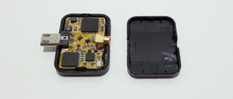
Connecting to a router
Those who have experience can easily solder to the contact pads on the circuit board inside the router.
Otherwise, be careful, thin traces may come off the printed circuit board when heated for a long time with a soldering iron.
You can connect to an already soldered piece of cable from a native antenna via an SMA connector. You shouldn't have any problems purchasing any other N-type RF connector from your local electronics store.
What is this device
A modern homemade antenna gun for the Internet is a device that allows you to receive and transmit a wireless signal over long distances. Depending on the installation location and terrain features, it is capable of normal interaction with the transmitting device at a range of up to 10 km.
The impressive transmission range has made this antenna very popular among users. In addition, it is very easy to assemble it yourself. At first glance, the finished device resembles a futuristic laser that can operate in a directional manner. In this regard, when the device is directed to a place with a high signal concentration, it is able to easily receive it.
Using this antenna, you can easily intercept or catch someone else's Wi-Fi signal. In this regard, if you notice such a device directed towards your personal router, it is better to take security measures - set or change the password.
About the range of Wi-Fi antennas
From a native router antenna of 2 dBi, a 2.4 GHz signal of the 802.11n standard can spread over 400 meters within line of sight. Signals of 2.4 GHz, old standards 802.11b, 802.11g, travel worse, having half the range compared to 802.11n.
Considering a WiFi antenna to be an isotropic emitter - an ideal source that distributes electromagnetic energy evenly in all directions, you can be guided by the logarithmic formula for converting dBi to power gain.
Isotropic decibel (dBi) is the antenna gain, determined as the ratio of the amplified electromagnetic signal to its original value multiplied by ten.
AdBi = 10lg(A1/A0)
Conversion of dBi antennas into power gain.
| A,dBi | 30 | 20 | 18 | 16 | 15 | 14 | 13 | 12 | 10 | 9 | 6 | 5 | 3 | 2 | 1 |
| A1/A0 | 1000 | 100 | ≈64 | ≈40 | ≈32 | ≈25 | ≈20 | ≈16 | 10 | ≈8 | ≈4 | ≈3.2 | ≈2 | ≈1.6 | ≈1.26 |
Judging by the table, it is easy to conclude that a directional WiFi transmitter with a maximum permissible power of 20 dBi can distribute a signal over a distance of 25 km in the absence of obstacles.
A further increase in antenna power is unreasonable; the signal will propagate in too narrow a disk-shaped zone.
Author: Vitaly Petrovich, Ukraine, Lisichansk
Design features and types
Based on their design features and types, antennas differ in several categories. These are the main ones:
- Antennas with different directions;
- Wideband or multifrequency.
Note! It is necessary to consider each type separately
Directed
There are three different types of signal amplifiers in this category:
- With the possibility of direction in one specific direction. This category is easily identified by its name. Such an antenna can only operate in one direction. It must be positioned directly towards the location of the operator's distribution tower. In turn, this ensures that a high quality signal is received from only one direction. However, this requires high accuracy in indicating the location of the base station, and in the event of an outage at this station, the connection will simply disappear until the problems are corrected;
- Omnidirectional, that is, capable of amplifying a signal from several directions. In this case, the amplifier is able to independently select the most uninterrupted and high-quality signal from one of several suitable towers. The antenna automatically adjusts and switches between stations if signal reception is lost or deteriorated. The disadvantage is the weak power of omnidirectional devices. Able to work only in cases of short distance from the station;
- Sectoral. Just like the first ones, they are capable of working in one direction, but cover a much larger area. They can receive signals from several stations of the same sector at once, and in case of interruptions, switch independently. The quality of data reception amplification is quite comparable to the first type of device. The disadvantage is the increased price compared to analogues.
Specifications
Various types and types of antennas differ in their technical characteristics.
However, when choosing, you need to know the main characteristics that such devices provide:
Main technical characteristics:
- Operating frequency range, measured in MHz;
- Gain, dB;
- Input impedance, Ohm
- SWR (gain);
- Polarization, vertical or horizontal;
- Operating temperature range, °C;
- Wind load, m/s;
- Overall dimensions, mm;
- Weight, kg;
- Material: aluminum, steel.
External antenna
Shooting from windows is of course good, but this thing is more suitable for outdoor street use. So now we need a coaxial cable with a connector.
We must solder the base that goes around the wire to a large circle, and the core itself to the next circle. If the core is too small, simply pull out the wire and expose the required length of the core. That's it, she's ready! After this, we attach a powerful Wi-Fi antenna-gun and install it as high as possible.
You can use a bracket for reliability. To connect two networks over a long distance, it is worth making the same one. True, you will then have to catch the second net and put it in the right position. After the launch of the antenna, 4 times more WiFi networks appeared. If you try to use it in the city, there will be even more.
Long range Wi-Fi antenna
Such a device will significantly enhance signal reception and transmission. If conventional antennas deliver signals within a maximum radius of 5 kilometers, then a long-range transmitter will increase this value to 10 km.
The step-by-step production of a Wi-Fi antenna with your own hands will be as follows:
- prepare fiberglass laminate that will be used as a reflector;
- cut it to a rectangle measuring 10 by 14 cm;
- drill holes for the cable in the middle of the plate;
- taking a copper wire, build the antenna directly, it consists of two squares connected to each other;
- solder the cable to the copper squares;
- Attach the antenna to the reflector.
The design of the Wi-Fi antenna device is quite simple: a reflector, the antenna itself, made of copper wire and a cable. This design, despite its simplicity, is capable of delivering a signal over a long distance.
Advantages
When manufacturing an external-type 3G gun, one should adhere to the generally accepted theory of antennas, which implies that the wavelength of the signal depends on the geometric dimensions of the device. The advantages of external structures are represented by mechanical strength, low windage and resistance to temperature changes.
If you move the gun outside the living space, this will eliminate possible attenuation and weak signal reflections that may occur due to walls, ceilings, furniture or partitions. It is strictly not recommended to increase the length of the wire from the modem to the antenna, because signal attenuation is also observed due to the cable.
Outdoor testing
You can install and direct a gun on the street to any place and move away from it at a certain distance. This makes it possible to check what signal transmission range it has.
Test results carried out by amateurs showed excellent signal quality at a distance of 300 m. At greater distances, the communication level became slightly lower, but data transmission continued. As a result, the range limit was 3 km. After this, the phone could not find the required network.
Interesting! The antenna power of the smartphone itself is also important. For example, the use of similar guns to receive and transmit signals makes it possible to exchange data at a distance of up to 10 km.
Having considered how to make a Wi-Fi gun, carrying out the necessary calculations and installing it, you can come to the conclusion that with its help it is easy to set up the Internet in a country house, garage, country house or any other place remote from the city. The device is suitable for distributing a signal to friends or acquaintances within the city at a distance of up to 1 km, if there is no serious interference.
Antenna up to 50 kilometers
This device is not difficult to make with your own hands following the principle described above. The main difference is the large size of the reflector, approximately 35 by 45 centimeters.
Vibrators made of fiberglass are installed on it.
In other points, the diagram for manufacturing a Wi-Fi antenna capable of receiving and delivering signals at a distance of 50 kilometers will be similar to the step-by-step description of manufacturing a long-range antenna.
If you need to strengthen the received Wi-Fi signal, do not rush to visit stores with expensive routers and add-ons for them. It is possible to improve the performance of an existing antenna using additional reflectors and arrays.
Try to make a powerful transmitter with your own hands; it will receive and deliver signals much more efficiently and clearly even over long distances. The above instructions will help you make a powerful, long-range Wi-Fi antenna.