In some situations, owners of private houses may need a pressing device with an impressive pressure indicator. Buying such a tool is irrational, since it requires significant financial investments, and the device will not be used so often.
This article will discuss the drawings of a hydraulic press and describe the algorithm for its manufacture at home.
Mechanical type of unit
The most common presses made at home are:
- Mechanical presses
- Hydraulic presses
These types of tools are best suited for use at home or in the garage as they take up little space.
This type of installation is quite popular due to its small dimensions. You can make a mechanical press of any mode (automatic or manual) with your own hands. The simplicity of the design ensures its reliability and provides good resources.
An approximate model of a mechanical press made by yourself can be seen in the photo on the Internet.
A mechanical press is capable of processing:
- Cardboard
- Rubber
- Plastic (and other polymers)
- skin
- Metals
What in the end...
A homemade hydraulic press is always useful for working in the garage. In addition, it can always be used around the house. For example, pressing juice from fruits and even squeezing oil from either sunflowers or nuts. To make it, I used ordinary materials. And the assembly method is optimal for those who are not familiar with welding.
Question
Write in the comments what you think - is it so important which side to place the jack on the bed? As for me, for household purposes the device has an even greater power reserve. And you don’t have to bother with modifying the jack...
Jack and its features
The press is based on the mutual work of two cylinders of different sizes. From the chamber that has a smaller size, with increasing pressure, the liquid is transferred to a chamber with a larger size.
The interaction of these cylinders with pistons having different diameters constitutes the work of the structure. In this way a strong pressing effect can be achieved.
A version of a homemade garage press can be seen in the photo on the Internet.
To make a hydraulic press, a glass jack is most often used. It has a relatively low cost and is capable of producing a pressure of 20 tons.
There are two ways to assemble a jack-based hydraulic press in your garage:
- Position of the jack at the base of the mechanism (pressing upward)
- Position of the jack at the top of the mechanism (pressing down)
Jacks have a parameter for the correct position. Some jacks cannot be used in an inverted position. Therefore, before starting work, you need to make sure of the capabilities of the selected equipment.
DIY roller press for flat die cutting
- corrugated cardboard, micro-corrugated cardboard - boxes, trays, pizza packaging, crates. - cellular polypropylene - transport packaging boxes, shells, industrial transport packaging, packaging for large-sized products and in-shop containers.
Cutting of complex contour products
- cardboard, paronite - puzzles, gaskets, sealing elements. - fabric, felt, leather, polymer materials and films - souvenir magnets, trimmings for blister packaging, disposable tableware, trays.
- polymer foam materials - seals, heat and sound insulation pads, soft puzzles, soft children's construction sets, packaging inserts, various profiles for protecting the ends and corners of furniture, for the manufacture of volumetric magnets.
The roller press has two steel shafts located one above the other; the top one has a plastic pipe jacket on it.
The main form-building element is a punch mold, consisting of a sheet of plywood with cutting, scoring, and perforating knives inserted into sawn grooves.
When feeding a die with a workpiece laid on it between rotating shafts, the knives cut into the bandage and the product is cut out to form creasing lines.
When feeding the workpiece into the cutting zone, the die is usually turned with an approach angle of 10-15 degrees. This increases the durability of the knives. Therefore, the maximum width of the die along the front depends on its length (taking into account the angle of rotation of the die).
Our machine has many interesting and necessary little details that make it very reliable and make working on it more comfortable.
ROLLING SHAFT BLOCK consists of:
LOWER SHAFT , which has high-strength surface hardening and chrome plating . The runout tolerance is no more than 0.03 mm.
UPPER CUTTING SHAFT, consisting of a thick-walled steel pipe with a polymer bandage on it (polyethylene pipe 160x6.2).
Using a plastic pipe as a BANDAGE allows the client to:
1. do not have problems with the need to groove it in case of uneven wear, as happens with cast bandage shafts.
2. do not use any lifting equipment when replacing,
3. do not depend on the equipment supplier.
ADJUSTMENT OF THE DISTANCE BETWEEN THE SHAFT is very precise, within 0.1mm. Rotation of the adjustment knob results in transmission through worm drives to both sides of the shaft, then to screw pairs. In this case, both ends of the shaft move synchronously, that is, simultaneously on both sides, so there is no skewing.
To improve the operation of the cutting mechanism, the principle of “hanging the upper cutting shaft” is applied.
When punching, a load equal to the punching force is applied to the upper shaft. The shaft rises slightly (by the amount of play in the clearance adjustment). After cutting, the load drops sharply to zero - at this moment the shaft goes down.
If the upper shaft “hangs” on the screw gear and is not artificially pressed to the top point, i.e. If the backlashes are not selected, shock loads will occur on the screw gears during operation. In our presses this problem is solved constructively.
The shaft is always pressed to the top point due to spacer springs and no impacts occur.
Read also: Electric spray gun for whitewashing with lime
ROTATION TRANSMISSION TO THE UPPER SHAFT is a necessary condition for high-quality cutting and durability of the mold. If, at the moment the mold enters the gap between the shafts, the upper bandage shaft is at rest, the mold will crash into it with the entry knives, which will lead to their rapid failure.
In addition, forced rotation on the shaft is desirable only for its acceleration. Further, when the mold enters the gap between the shafts, the transmission of rotation from the drive shaft to the counter shaft is carried out by the mold itself. Therefore, at this moment, a hard transfer will only harm.
To ensure that both of these mutually exclusive conditions are met, the rotation transmission is made in the form of a flat belt. At the starting moment of acceleration, it allows the bandage shaft to spin, and at the moment of cutting, even if the peripheral speeds of the shafts do not match, it will slip.
MOVEMENT OF THE DIE FORM during cutting occurs with the help of conveyor belts, which facilitates the work of operators and speeds up the work process.
The DRIVE for rotation of the cutting shafts is equipped with a smooth start and stop with variable speed, which has a good effect on the dynamics of the machine, smoothness and softness of operation, and, consequently, on the wear of all drive mechanisms. As a result, its durability increases.
The CONTROL PANEL operates in three modes:
1. manual (moving the form only when you press the button post of one of the operators)
2. automatic (reverse movement of the form with stop-pause for loading and unloading)
3. adjustment (moving the mold from the control panel)
The main operating mode is automatic, when operators set the pause time for loading and unloading separately on each half of the table. This frees the operator from having to press buttons to start the cycle.
The PORTABLE MANUAL CONTROL POST has magnetic “suction cups” that securely hold it on any metal table surface, including the side one.
The design of the button is made using an inductive sensor, which eliminates mechanical switching, as happens in a conventional button. Thus its reliability is very high.
SPECIFICATIONS
Working shaft length 2500 mm.
Plastic shirt parameters:
Material. PE (polyethylene)
Outer diameter, mm. 200
Wall thickness, mm. 11.9
The goods are delivered on wooden pallets, packed in stretch film.
Dimensions of transport spaces (mm):
1. L2750*W1400*H1750. gross weight 700kg±10
2. L3100*W800*H1300. gross weight 700kg±10
© Ortho. Production of equipment for corrugated packaging.
- © 2014 — 2022 MosCatalogue.net
- Blog
- Requests
- Copyright holders
- Denial of responsibility
- Privacy Policy
- Terms of use
- About the service
- Contacts
About the moscatalogue.net service
MosCatalogue.net is a service that gives you the opportunity to quickly, free of charge and without registration, download videos in good quality. You can download videos in MP4 and 3GP formats, and you can also download any type of video.
Read also: Hydraulic wrench for tightening bolts
Search, watch, download videos - all for free and at high speed. You can even search for movies and download them. Search results can be sorted, making it easier to find the video you're looking for.
You can download films, clips, episodes, trailers for free, and you do not need to visit the site itself.
Download and watch an ocean of endless videos in good quality. Everything is free and without registration!
I was puzzled by the search for the press, maybe I was looking poorly. But for operational printing, in addition to roller presses of which the cheapest is about 2 thousand. I didn't find anything specific.
Parameters: cutting area A3+, relatively light weight, electrics 220, cliche stroke at least 10 cm. Use: for cutting cardboard (puzzles), magnetic vinyl.
I wrote a letter to one company, the answer is in the attached file. Device price = 95 thousand rubles.
I would like to discuss this device, because... the company produces them itself and can take our comments into account. I think the same for the price.
It was not possible to upload files “Association of Consumers and Manufacturers of Forging and Pressing Equipment” Voronezh, st.
Solnechnaya, 8a, 5th floor, Association of Manufacturers and Consumers of Forging and Pressing Equipment “In continuation of the telephone conversation on the supply of equipment for cutting parts from cardboard, vinyl, we suggest considering a pneumatic tabletop press model PPN-2 (U.S. 2 t.s. ) (description and characteristics of the press are presented in the Appendix). The cost of the PPN-2 press is RUB 95,000.0. VAT included."
No. Name of parameter PPN-2
1 Nominal force, kN 20 2 Rod stroke, mm up to 100 3 Number of rod strokes per min, min-1 up to 100 4 Open height, mm 150.
250 5 Dimensions of the working surface of the table, mm 350x450 6 The largest number of single strokes of the rod per minute 100 7 Diameter of the hole in the end of the rod, mm 20N8 8 Nominal air pressure, MPa 0.5 9 Compressed air consumption per cycle, l 4 10 Overall dimensions in plan , mm 320x550 11 Height (maximum), mm 700
12 Press weight, kg 167
Photo is avaiable. I can send the letter you sent by email.
| Kuban user menu |
| View profile |
| Send a private message to Kuban |
| Find more posts by Kuban |
Necessary materials
To make a press, prepare:
- channel P-14;
- pipe 40*40 mm round or square section;
- corners;
- steel sheets (optimal thickness - 7 - 8 mm);
- centimeter thick metal plate;
- a piece of pipe measuring 10 - 15 cm.
Structural design and assembly features of the vacuum model
The design of the vacuum-type model has certain specifics, which it is advisable to study in advance. Preliminary familiarization with this information will allow you to better understand how to build such equipment.
Looking at the pictures of a vacuum-type hydraulic press, we can distinguish three basic units:
- Bed or frame.
- Working surface.
- Pneumatic system.
The model under consideration has the following structural nuances:
- The tool is designed for manual operation.
- Assembling the press does not require the use of any unavailable materials or complex devices.
- In terms of efficiency, do-it-yourself hydraulic manual presses do not differ from industrially assembled equipment.
Collection of raw materials and pressing
The plastic recycling process begins with the receipt of raw materials. No special license required.
Many stop at this stage and start a full-fledged business. It consists of collecting raw materials, pressing them and then selling them.
Garbage is actually only conditionally free and not everyone has access to city landfills. Therefore, if you do not do this on an industrial scale, you can try to exclude the landfill administration from this chain and receive raw materials directly from people and enterprises.
This can be done either through collection points or by installing special boxes around the city for collecting plastic bottles.
People throw bottles into such boxes for free, because they understand that in this way they are making their small contribution to improving the environment. You can also work with people’s awareness by hanging explanatory signs on such boxes.
To place such a box in the courtyard of an apartment building, you should first coordinate this issue with the management company or a representative of the HOA. The argument for installing a box is to help keep the yard clean.
You can also agree on the installation of separate boxes (for plastic, paper and glass) in the offices of large enterprises. Thus, the enterprise will not only receive an “eco-title” and free waste removal, but also additional funds for small consumables.
Subsequently, bottles from such points are removed and pressed into bales. For pressing you need a press. The most budget option is a manual press, which you can take with you when collecting raw materials. But for greater productivity, you need a hydraulic press.
How to calculate parameters and make a mechanical press
Mechanical devices are needed to process leather and metal products. They can also be used to recycle cardboard boxes and foam.
Here are instructions on how to make a mechanical-type hydraulic press yourself:
- Cut the steel corner into 4 pieces of 90 cm each and weld to 4 corners, 55 cm long. You should get two metal rectangles
- Secure them with steel pipes.
- Strengthen the made box using crossbars and steel plates.
- Organize a small gate in one of the walls to remove processed parts.
- Start forming the piston. For this purpose, weld channels measuring 55 - 65 cm together. Reinforce the workpiece with a steel cross member, attach a flange to its middle, into which insert a metal rod ahead of time. Next, weld the channel structure to the previously made box.
- Place a washer with a nut and a bearing on the rod.
Assembly steps
Let's look in detail at how to make a homemade press from a jack using bolted fasteners. And first of all, you need to draw a drawing or take a ready-made one. Then prepare all the necessary materials and tools.
For work I needed:
- Square pipe with a cross section of 50×50 mm.
- Metal corner 40×40 mm.
- Steel strip 40×4 mm.
- Steel plates 10 and 4 mm thick.
- 2 coil springs.
- 2 long J-bolts.
- Bolts with nuts: 12 pieces M10x60 and 2 pieces M10x80.
- Hex bolts: 3 pieces M10x30 and 4 pieces M8x16.
- 2 bolts M10×16.
- 4 bolts M6×16.
- Rod with heel.
I divided the entire assembly of a homemade hydraulic press from a jack into stages:
- Since I have a five-ton jack, according to its parameters, I cut two pieces 66 cm long from a square pipe. They will become the main racks in the machine. And he immediately divided the corner into two 30 cm sections. They will go on the legs and this length will be enough for stability.
Source alicdn.com
- On one side of the corner I find the middle and mark on this line 2 future holes for an M10 bolt. I repeat the operation with the second corner and carry out drilling. Then I apply the corners to the ends of the square pipes, align them with the square and make markings through the already prepared holes. After that, I drill through holes at each mark on the pipes. And I attach the legs to the posts with the longest bolts.
- I cut two pieces of 40 cm each from the corner. From them I make an upper reinforced support for the press from a jack. I align the edges of the corners with the top of the square posts. I also drill out the corner first. Then using it, like a template, I prepare two through holes in the squares. And I connect the parts with long bolts.
- I cut a blank 8x13 cm from a thick plate. It will serve as a stop for the jack piston. I cut out another piece from a thin slab to the same dimensions. I make one hole in both plates along the edges, followed by cutting a thread for an M10 bolt. In a thin piece, exactly in the center, I use a milling cutter to cut a hole to the diameter of the jack rod. I turn the rack over and place the slabs across the corners. I mark holes in them for the M10×30 bolt. I screw the plates through the threads prepared in them so that the blank plate fits against the corners, and the thin one with a hole for the rod covers the thick one.
Source kdyproducts.com
- For a sliding support under the bottom of the jack, I first cut two 16 cm pieces from the steel strip. I step back 5.4 cm from each side and make a wedge-shaped cut with a grinder. I bend the strip, making a U-shaped part out of it that will wrap around the stand and slide along it. I attach the parts to the posts and measure the distance between them. I add 8 cm to it and cut off a long strip. I retreat 4 cm from its edges and make similar cuts. I bend the ends at an angle of 90 degrees. Next, I connect the parts together with short bolts, having previously cut threads on the U-shaped parts.
- I place the jack on a thin slab and trace its sole with a slight tolerance. I cut the workpiece and attach it to the strip with two bolts along the edges, having previously cut the thread. I cut off the protruding parts of the fastening.
- I make 4 holes in the base of the jack along the edges and cut threads into them. I make marks on them on the plate and carry out the same operation. In the center of the plate I make a through hole for an M10 bolt with a hex head. I widen it on one side to hide the bolt head. I step back 3 cm from the base plate in each direction and drill holes on the strip for J-head bolts for the springs.
Source hamradio.co.uk
- Assembling a homemade press occurs in the following sequence. First, a bolt is screwed into the plate so that its head is hidden. Then the jack base is attached to the slab. Bolts under the spring are inserted into the strip and secured with nuts on both sides.
- Holes are drilled on the sides of the top stop, opposite the J-head bolts. Long M10 bolts are inserted into them and springs are hung on them. Their other ends hook onto the hooks of the lower bolts.
- For a stand for pressed parts, I cut two 40 cm blanks from the corner. For rigidity, I insert two pieces of square pipe between them. Along the edges I make through holes for steel pins that will pass through the posts at given levels to hold the platform.
- I cut the steel rod with the heel to the required length. I drill a blind hole at the sawn end and cut a thread in it. I screw the prepared rod onto the bolt, which was previously hidden in the lower stop of the jack.
- All that remains is to make through holes in the racks to hold the stand for the pressed parts at the desired level.
More holes can be made in the racks for the stand in the future. Based on immediate needs. In the meantime, I replaced the standard jack handle with a long pipe for ease of use. And he carried out the first test by pressing out the old bearing. The machine demonstrated complete stability and easily coped with the task. All that remains is to prepare a container for squeezing out the juice and proceed to storing it for the winter.
The video will clearly show how to make a press from a jack using the described method:
How to make your own hydraulic press with electric drive
Equipment such as an electro-hydraulic press, due to its versatility and high efficiency, is actively used both in large manufacturing enterprises and in small workshops, as well as at car service stations. Using a hydraulic press equipped with an electric drive, you can solve many technical problems, which include:
- pressing, pressing out of gears, bearings and shafts;
- stamping, straightening and bending of metal products;
- pressing of products made from wood shavings, plastic and metal.
The electro-hydraulic press R-342M is intended for performing work on pressing, straightening and pressing in repair shops
A serial electro-hydraulic press will be quite expensive, but you don’t have to buy it, but make it yourself.
Serial hydraulic presses with electric drive are quite expensive, so it makes sense to think about how to make an electro-hydraulic press with your own hands. To do this you will need the following tools and equipment:
- welding machine;
- lathe;
- drilling machine;
- Bulgarian;
- electric drill.
This press will be able to produce a maximum pressure of 35 tons
The supporting structure of the electro-hydraulic press, which is subjected to the main mechanical loads, is the frame, the strength of which should be given special attention. A T-beam made of metal of such thickness that it can withstand the loads created by a hydraulic press without bending is well suited for these purposes.
Press frame made of I-beam
Structurally, the frame of a homemade electro-hydraulic press is a U-shaped frame, welded from T-beams and installed on a base, for the manufacture of which thinner channels and angles can be used. In the middle part of such a frame (along its height), a working platform is welded into it, for the manufacture of which thick-walled channels are used.
Particular care should be taken when attaching the hydraulic cylinder to the frame of a homemade electro-hydraulic press. In order for such fastening to be as reliable as possible, it is better to fix the hydraulic pump on a 20 mm metal plate using a flange. The metal plate itself, which will absorb all mechanical forces, is mounted on two T-beams.
The rigidity of the structure is ensured by high-quality welding seams
The process of installing a hydraulic cylinder on the frame of a homemade hydraulic press is carried out in a certain sequence.
1. Adjustment of hydraulic cylinder, flange and plate
The body of the hydraulic cylinder, so that it can be placed in the inner part of the flange, is turned on a lathe.
The flange, which can be made from a car hub, is also processed on a lathe.
In order to make a hole in a metal plate that will be used as a base for installing a hydraulic cylinder, it is necessary to weld a round boss to it. With the help of the latter, such a plate will be fixed in the lathe chuck.
20 mm thick plate with a welded boss in the center
After the hole in the slab is bored out, it is welded to the beams of the base frame.
The flange, in which the mounting hole has already been prepared, is put on the hydraulic cylinder and welded in a circle.
Flange welded to hydraulic cylinder
It is very important that the flange and hydraulic cylinder are connected as smoothly as possible; for this, the adjacent surface of the flange must be machined on a lathe. 2. Installation of upper beams and hydraulic cylinder
The plate, which is already connected to the beams, is installed on the frame and connected to it by welding.
Through the holes on the mounting part of the flange, holes are drilled in the plate, which are necessary for placing the mounting bolts.
The installation of the upper beam is carried out strictly perpendicular to the supports
The hydraulic cylinder should not be attached to only one point, so it is necessary to make another flange, put it on the top of the cylinder and weld it to the beams.
Installing the Top Flange
T-beams installed in the upper part of the frame are connected to each other by welding.
3. Installation of the frame and oil station
In order for the hydraulic press you have made to fully function, you need to install an oil station on it and connect it with a hydraulic cylinder using hoses.
Installation of a frame and a two-flow hydraulic station delivering a pressure of 700 bar
Thus, it is not difficult to make a hydraulic press with an electric drive with your own hands. At the same time, you will have at your disposal equipment that can solve many technical problems.
Plastic recycling machine: an idea to note
Bottles, cans, toys and interior items made of plastic have long been part of our lives.
Despite the long service life of plastic, after the detergent or water runs out, the container is thrown away. As a result, plastics occupy one of the leading positions among household waste.
To solve this problem, and at the same time give people the opportunity to start their own business, Dutch inventor Dave Hakkens proposes using a small-sized plastic processing plant.
Dave Hakkens
Waste recycling, especially in developing countries, leaves much to be desired. Large industries prefer to use plastic obtained from industrial production rather than from waste. Plastic in trash cans is either burned or simply lies in landfills, polluting the environment. I believe that plastic waste is a real gold mine. The main thing is to approach its processing with imagination.
This article details what can be made from construction waste.
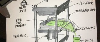
To bring his idea to life, Dave developed a portable, complete plastic recycling unit. All equipment can be placed in a garage or a small area. The mini-plant consists of a plastic shredder (crusher), a heating device and an injection molding unit.
Drawings of the device are freely available and can be improved by the user at his own discretion and taking into account available parts.
The mini-workshop operates according to the following algorithm: the collected plastic is sorted, cut, then put into a grinder, which crushes it into small pieces.
The raw material is then heated and squeezed out of the injection molding machine, like toothpaste, onto a mandrel or poured into a mold.
Dave Hakkens
The applications of recycled plastic are truly limitless. Starting from braiding for knife handles and ending with interior items.
By adding coloring pigments to the extruder, you can change the color of the finished product.
The Dutchman, using a plastic recycling plant, produces lampshades, baskets, flower pots, stands, as well as door handles and various useful household items.
Dave Hakkens
It is enough to make a new master mold and you can do what you need.
According to the inventor, he hopes that his concept will be in demand in Asian or African countries, which will allow the poor to earn money by getting rid of garbage.
All parts of the installation are made of simple parts; it does not contain complex and expensive electronic components.
In addition, Dave believes that each user of the device, having downloaded the plans and assembled the installation, will share his experience with others and talk about his improvements.
At the moment, the third version of the device has been made. In the future, Dave plans to upgrade the installation and combine it with a 3D printer.
Thus, the functionality of the mechanism and the types of products produced will expand. For example, it will be possible to make complex three-dimensional products, sculptures or parts for tools.
On FORUMHOUSE you can read an article that describes a budget model of a 3D printer. Also interesting is the material about the unusual robot gardener.
All do-it-yourselfers will benefit from the section that tells you how to make machines, tools and mechanisms with your own hands that simplify the construction of a house and work on the site.
And this video shows what tools are needed to build a frame house.
We create a press with electric drive
To make a power press, you will need an electric motor. Let's consider an approximate sequence of actions:
- Make a frame from 2 guides made from square steel pipes.
- Drill holes in the pipes to attach the platform.
- Create a “lift” to allow the press platform to move (use steel angles).
- Make a pressure platform using a high-strength channel.
- Install the jack and connect a pedal to the structure to control the power of the pressing device.
The nuances of making a mini-pressing device
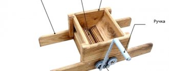
Many craftsmen give their preference to small-sized designs. Such people will certainly like the mini-press, which offers a desktop installation method.
Such a device is easy to manufacture, but it is rarely used due to its low practicality. For example, it is used if you need to chop walnuts or compress containers made of tin or plastic.
The frame of the mini-press is assembled from durable lumber. A rectangular frame is made from 4 boards. A mobile wooden pressing surface is installed in its upper part. The hydraulic system is made from standard medical syringes.
Pneumatic press based on timer and temperature controller
Pneumatic press for perforation and hot stamping
In this article I will describe the design and electrical circuit of a pneumatic press for hot stamping on leather and cardboard, which I assembled with my own hands. Such pneumatic presses can be called differently, depending on the scope of application.
Unlike a hydraulic press, which is driven by a hydraulic pump, a pneumatic press develops pressure using compressed air produced by a compressor.
Based on the diagram and design described in the article, the following types of presses can work: perforation, hot stamping, various presses for molding and gluing parts.
Here, as an example, is my article about installing the Euroautomatika RT-820M temperature relay in a similar Turkish press.
Home use options
Use a hydraulic press if necessary:
- squeeze the metal part out of the shell;
- press out or compress the bearing or rubber-metal hinge;
- straighten an element or connect two products end to end;
- bend any piece of metal.
The device is also suitable for producing fuel briquettes used to light the stove. The advantage of using compressed sawdust is long-lasting combustion and the absence of smoke formation, as well as the creation of intense heat.
To form briquettes from coal chips, you will need to slightly change the mechanism. The main parts of such a press will be the work table, base, bed and drive.
Excellent results are achieved by using pressing equipment for recycling plastic bottles and cans. It easily transforms containers into neat layers.
The hydraulic type device can be adapted for a hay pick-up. To do this, you need to supplement it with a cobblestone or steel frame without an upper fragment. Using special fasteners, this structure must be attached to the front. You will also need a transport pick-up and a running element.
When is an industrial press needed?
If we are talking about small volumes of PET bottles that need to be compressed, then a self-made machine is quite sufficient.
For large industrial enterprises and plastic bottle collection points, such a machine is unlikely to be suitable, since they are characterized by low productivity and a high degree of labor involvement.
It simply cannot cope with a large flow of material, since here a favorable ratio between the speed of work and the amount of compressed material is already necessary.
Another factor that can sway the choice in favor of industrial equipment is the safety margin. Undoubtedly, the quality of the welds and the strength of the metal directly determine the service life of the machine.
You can read about presses for industrial plastic waste here.