Russian knife craftsmen never look for easy ways. Because this is a hobby and passion for many. It happens that a simple activity turns into a real small business. But for the most part, for people it’s still a relaxation and distraction from everyday life. Each person determines his own leisure time. Forging enthusiasts quite often make their products from unusual things, for example: a knife from a bearing. A very interesting and difficult process.
Homemade knife from a bearing.
Pros and cons of a bearing knife
Many ordinary people will say that why do this when you can go to the store and buy yourself a couple of wonderful blades. But we don’t tell them how to spend their time. So if you’re not interested, go to another resource, and here there will be an article containing a lot of useful information, especially for beginners. Because the presentation is planned in a step-by-step perspective.
We have already written that there is no “ideal knife” for all occasions. And this is true, but you must always strive for the ideal. Therefore, let's try to highlight the positive and negative aspects of the blade from the bearing. To know what will happen as a result of proper metal processing.
Bearing steel is originally designed for high loads, for this reason it is characterized by ductility and uniformity when heated. The end result is a product with a hardness of 61 to 64 units on the Rockwell scale. And most importantly - the highest wear resistance of the blade.
The only downside is the fragility during processing. It is very important to perform the hardening correctly, and to exclude “cold” forging altogether.
Installation of sliding assemblies
Such parts can be one-piece or detachable. The installation features primarily depend on what type of product is planned to be replaced. If we are talking about the first group, the bearings are first pressed onto the shaft and secured in the housing. This can be done not only using special pressing equipment, but also manually. In this case, the step-by-step instructions look like this:
- • The sleeve fits onto a mandrel that is centered in the hole.
- • Using a hammer, the structure is carefully inserted into the seating slot. It is important to avoid distortions.
- • The already pressed bushing is secured with special stoppers.
If you press the bearing onto the shaft correctly, you can achieve high wear resistance from the nodal support. The external condition of the element used is important. If there are scratches, chips and other damage on it before starting work, it is better to replace the part. When receiving a strong load, the damaged element will continue to collapse. A small abrasion can quickly become a serious problem. Especially if there are accompanying problems with lubrication or incorrect installation.
Detachable structures are installed separately in the base and cover of the mechanism. This leaves a small gap allowing normal operation. An important feature is the need to adjust this type of nodal supports, regardless of whether the replacement is made in a home workshop or in mass production. Moreover, this is already accomplished during the initial inspection. Correct installation is assessed by how freely the part slides in the structure.
Sharpening and polishing the blade
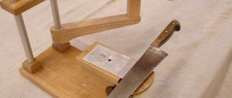
Let's move on to such an important point as sharpening the knife. When doing this, symmetrical sharpening on both sides of the blade is important. It is also necessary to create the required bevel angle of the knife blade, which for ordinary knives is 15 - 25º. On razors, the smallest angle is 8–15 degrees, on tourist knives 25–30º. Manually sharpening a knife blade on a whetstone is unproductive. This is done simply and efficiently on a belt sanding machine called a grinder.
If you need to sharpen a knife to razor sharpness, special sharpening devices with replaceable abrasive bars are used. With the help of such equipment, it is not a problem to create any angle of descent from the butt of the knife or descent of the cutting edge of the knife.
Once the rough shaping and sharpening of the knife is complete, it's time to fine-tune the metal using a grinder and Dremel attachment. Through holes are drilled for the pins for attaching the knife handle. In order to better bond the wooden plates to the metal, about a dozen blind holes are made on both sides of the knife shank.
Main stages of work
First of all, you need to cut a piece of a suitable width from the pipe and clean the edges of the cut with a grinder to remove any burrs that have formed.
Then you need to make a slot in it - using the same grinder with a cutting wheel or on a band saw.
At the next stage, using a hammer and a bench vice, the master reduces the diameter of the holder to the required size and welds the edges together.
After this, we press the bearing into the housing and weld a metal washer to one of its sides.
Next, cut off a piece of strip and two pieces of corner. We weld them to the race with the bearing.
For details on how to make a bearing housing without a lathe, see the video below.
Source
Preparation of overlays
The ergonomics and overall perception of the knife depend on the correct choice of material for making the handle. Metal alloys, plastics, genuine leather, and elastomers are used as the starting material for the manufacture of knife handles. Hard and valuable wood species are irreplaceable for this purpose.
The overhead handles, most suitable for the shank of the bearing knife, consist of 2 identical halves. You will need to stock up on scraps of metal rod for the knife handle pins. In the case of using wood, the following sequence should be followed:
- the antiseptic-treated block is clamped in a vice and sawn into 2 identical parts;
- to eliminate gaps, thoroughly sand the sides in contact with the metal;
- the contour of the knife handle is drawn, two dies are cut out with a jigsaw;
- the halves are placed on the shank, the holes for the pins are marked and drilled.
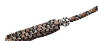
Handle preparation
Tools you'll need
A range of mechanical tools have been developed to simplify the installation process. In particular, NSK offers the following products:
- The FTN333 mounting kit is an excellent option for installing small to medium diameter bearings (from 10 to 55 mm) using the cold fit method. This way you will complete this operation correctly and without any problems.
- Wrenches - available in standard and reinforced versions. Indispensable when installing locknuts. This is a simple and inexpensive means of mounting tapered seat bearings.
For the convenience of working with large diameter bearings, the company offers hydraulic equipment:
- Pullers, pushers and puller plates – provide large loads to maintain the recommended contact force between the part ring and the surface. They simplify the installation process and eliminate the possibility of errors during installation.
- Nuts – Using the offset method, they increase the accuracy and speed of installation of tapered bearing components. They have an anti-corrosion film, which means they have a long service life.
- Pumps - intended to be used together with nuts, pump oil and greatly simplify the operation.
In addition, induction heaters have been developed for each bearing size. NSK offers a range of devices in different sizes and capacities. They ensure optimal and safe parts temperatures to ensure a smooth shrink-fit installation process.
Kinds
These mechanisms can be divided into groups according to the direction of the load, according to the elements on which the holders rest, according to the presence or absence of a rotating spacer and according to the material of manufacture.
What are they made of and how are they made?
The product can be radial and supporting, with full or partial rotation. Depending on the operating conditions, it is manufactured in the form of: outer and inner races (lower and upper), sliding sleeve (washer), lubrication system (forced, natural, air).
Polished surfaces, due to the lubricant or due to the physical properties of the gaskets, provide long-lasting easy sliding. Raw materials for production: steel, cast iron, bronze, fluoroplastic, babbitt, aluminum, ceramics. Pairs with a minimum friction coefficient are selected. What metal the bearing bushing is made of directly determines in which cage it will rotate.
Rolling
Such units are divided into radial, thrust and complex. This determines the direction of the load. The first are divided into three main classes: ball, roller, needle. These species can be with or without restrictive rings, with one or two anthers, and completely open.
The second type is created on the basis of spherical elements, cylindrical and conical rollers. Completely collapsible varieties are available. The third – combines the qualities of the first and second in terms of perceived effort. There are also open and closed types.
Depending on the materials for the manufacture of rolling bearings, there are several subclasses:
- • standard (most common);
- • designed for increased loads;
- • designed for extreme temperatures;
- • resistant to aggressive environments.
For special conditions (ultra-high rotation speeds, strong heating, the need to operate in the presence of acids and alkalis), products made of ceramics, silicon nitride, and plastics are used. There are models where the sliding layer is a gas or a magnetic field.
Case types
There is a certain classification of bearing housings. Each type differs in its purpose, mounting method, configuration and size. The following varieties are standard today:
- stationary solid;
- stationary detachable;
- flanged.
The one-piece stationary type of case is made of pure nickel, which makes it more rigid and simpler. The axial fit of bearings in the housing has a complex axial type of installation. Therefore, this variety is used in low-speed mechanisms that have a small shaft diameter.
The detachable stationary housing is made of gray cast iron. It consists of a lid and a base. These body elements are connected with bolts. This design makes it easy to change the bearing when it wears out, make a secondary bore of the liner, and also adjust the gap. This is a common type of housing in mechanical engineering.
The flanged body is similar to the previous type. It consists of a base and a cover connected by bolts. It is used for very demanding parts. It serves as a support for both the end and through shafts.
Machining the bearing and preparing the part for forging
An outboard bearing for a car driveshaft or any other with a diameter of 100–150 mm is suitable as a knife blank. For example, it is allowed to use copies of the required sizes from the axial mechanism and drive equipment of machine tools and moving units. The direct source is the most massive part of the product, called the outer race of the bearing. It is made of structural steel grade ШХ15.
There are different methods for disassembling a bearing. Since you won’t need anything other than the outer shell, and you can’t split the shell under any circumstances, we’ll use the most “humane” method - sawing the metal with a grinder. It is better to clamp the bearing in a vice and, if possible, saw the inner ring. It is better to saw the outer ring diagonally, thereby forming the nose of the knife. After cutting with a chisel, the separator is destroyed and all the insides are removed along with the balls. If required, the cut area is opened with a metalwork tool. The circumference should be 1–2 cm longer than the knife, so the extra centimeters of the workpiece are sawed off.
Bearing housing without a lathe: a neighbor's experience
Personally, this knowledge is useful to me in a completely different direction: the axle of a windmill, the connecting rods of a homemade steam engine, and who knows what else: my neighbor’s project “trailer for a walk-behind tractor” is ongoing, and this time he came to visit with a ready-made unit for the rear axle instead of a gearbox:
The times when a familiar turner made workpieces lying under his feet for 0.5 fire water have sunk into oblivion. We have only one turner for the whole village and a lathe from the last century is “always under repair”, so you have to do everything yourself
In the end it turned out like this:
It's so simple
: the length of the outer circumference of the bearing is measured and an extra strip of metal is cut out from the pipe, after which the bearing is placed inside, and the entire workpiece is in a vice and with the help of a hammer and such and such the outer pipe is adjusted to the required size
All? Not yet:
To prevent the bearing from falling out of the housing, cuts are made in the pipe and the “antennae” are bent inward using a hammer and a magic spell (the method does not work without it):
Since Sergeich has two bearings in the housing, it was necessary to install a spacer between them, repeating the steps above: a pipe of a smaller diameter, removing the excess, etc. no welding, it’s just a “spacer” so that the bearings inside the race don’t move around.
The final assembly is installation of the internals and rolling of the assembly from the opposite side.
Video with the author's story:
Previous article from the “series” about a trailer for a walk-behind tractor: link
Source
general characteristics
The bearing housing is a special part. It is usually made of cast iron or other alloys. A bearing housing is used to seat the main shaft on the main platform. It secures the part tightly.
The housing and the bearing itself - rolling, sliding and other varieties - together create a unit. It is easy to find in the equipment and technology of enterprises in all industrial sectors.
Since quite a few types of the presented parts have been developed, there are even more cases for them. Moreover, manufacturers are ready to produce both standard configuration products and housings for specially shaped bearings. In the latter case, an individual drawing is created, on the basis of which the master produces the required part. This makes it possible to ensure that the unit complies with existing production conditions.
Features of operation
The bearing housing must provide the entire assembly with the required operating parameters. It operates under heavy loads and should not create an increased noise level. Extreme operating conditions of the unit should not reduce the durability of the housing and the entire mechanism.
Depending on the purpose, there are a large number of types of structures. Each manufacturer labels them differently. You can highlight the most popular manufacturing companies.
The housing has a spherical shape for installing the bearing itself. This allows the elements of the mechanism to be installed independently. Oil-repellent ring-shaped rubber seals are installed between the bearing and the housing.
Assembly
You need to dilute the epoxy glue. Marks should be applied to the dies being joined or shallow dents should be pressed for better adhesion of the epoxy layer. Be sure to degrease the metal part of the knife, which will be located inside the handle. Assembly is carried out in the following sequence:
- Epoxy glue is applied to the surface of the overlays from the scratch side;
- the halves are placed on both sides of the shank, pins are inserted into the holes, the assembled handle is wrapped in paper and tightly compressed with a clamp;
- after the epoxy has hardened, use a wood cutter to remove chamfers from the edges of the knife pads;
- Using sandpaper on a fabric base with a grit of 80, rough processing of the wooden dies of the knife handle is carried out;
- Polish the handle clean with strips of sandpaper.
The polished surface is covered with linseed oil heated to 50–60 degrees. After absorption, the procedure is repeated 2-3 times. There is no need to varnish the knife handle later. Under the influence of ultraviolet rays, the oil polymerizes, turning into a hard elastic substance. It fills the smallest pores of the wood, protecting the knife handle from moisture and external influences better than any varnish.
How to install an angular contact bearing
The difficulty of installing this type of assembly supports lies in the different diameters of the inner rings. One of them is always looser and has sufficient clearance to move, while the second is tight.
The scheme varies, but there is still a general rule. The loose ring is always placed on the stationary body part of the structure, and the tight ring is always placed on the rotating part. This installation allows the shaft to rotate quietly without interfering with the element or rubbing it. If you do not adhere to this basic rule, the entire structure will not work correctly.
In general, there are three fundamentally different options:
- • O-shaped, in which the mounted rings absorb axial load coming from two directions. This method is considered the most stringent and stable.
- • X-shaped, in which the nodes can also absorb double axial load, but with less rigidity, since they are placed facing each other.
- • Tandem, involves the perception of force in only one direction, and therefore often requires additional installation of an additional element.
The choice of a specific design solution depends on what type of nodal supports is used in the mechanism, how important the load capacity, noise insulation and other factors are.