Do-it-yourself crane beam for a garage-workshop
When we repair a car or assemble a vehicle with our own hands, it is often difficult to do without such a device as an engine lift.
A factory-made beam crane has significantly high prices, but at the same time, with its dimensions, you will be forced to look for space in the garage. However, there is a more profitable solution - creating a homemade beam crane with a collapsible structure. Its production requires significantly less money than when purchasing an industrial model of the lift. We offer a version of a homemade crane beam, which was built by one of the folk craftsmen.
List of materials required for the construction of the lift:
• racks – made of square pipe 100x100x2350 mm – 2 pcs.; • cross rod – made of seamless pipe, cross-section 100 mm, length 4150 mm; • rod supports – made of pipe, cross-section 110 mm, length 1200 mm, sawn into two parts. • base and bevels - from a corner 100x100 mm. • the supports are fixed to the rods using M 16 bolts.
Step-by-step making of a crane beam with your own hands
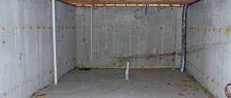
The master took the rollers for the cable from the elevator door drive.
The author installed the structure on rollers that were previously on a warehouse cart. To manufacture the lifting mechanism, a manual worm-type winch was used; its maximum lifting capacity is 1000 kg. The master welded it onto one vertical post.
The design is easy to disassemble and does not require much space.
Required tools and materials
To assemble the structure yourself, you must first prepare a set of tools and materials. In particular, you will need:
- square pipes for racks;
- seamless pipe with a cross section of 100 mm for the cross rod;
- pipes with a cross section of 110 mm for rod supports;
- metal corners 100x100 mm;
- M16 fixing bolts;
- telpher;
- welding machine.
Carrying out calculations
To ensure that the design matches the size of the room and functions in the required work space, it is important to carry out calculations before performing installation work. You can prepare a drawing indicating the dimensions of all components yourself or use a special calculator. The standard parameters in the calculations are the following:
- height no more than 2.5 m for repairing passenger cars and carrying out work that requires lifting and moving heavy objects;
- the load capacity depends on the type of hoist used and, as a rule, is 800-1000 kg;
- construction width - from 4 m;
- rack dimensions - 120 cm.
If there is a need to work with larger equipment, the lifting mechanism can be additionally equipped with vertical A-shaped racks. Also, if desired, it is possible to make the structure easily disassembled, which is important in conditions of limited space or in case of rare need to lift loads.
Worm worm hoists - a compact strongman
In addition to these main types of manual hoists, there are also others. Lately, worm gear hoists are often used. To operate, they are hung stationary or a mobile “cat” is used. This is convenient for moving loads horizontally; such hoists can move along I-beams. There are a lot of models of this type of device. They are used for lifting or holding loads in a raised position; they are also suitable for moving. Everything happens along a special suspended track made of I-beam profile.
Their advantage is that work can be performed in small spaces, and the distance between beams and loads can be insignificant. Such hoists can also be used for work outdoors.
They have some features, for example, a rotating casing (and the design can rotate all 360 degrees) allows you to control work from anywhere, that is, you can raise and lower the load in any position. This creates additional safety; during operation, the operator can be located on the side of the hoists and also from the load itself. This type of hoist is also distinguished by its reliability, wear resistance and low-heating brake. All this makes them quiet and comfortable. And thanks to the low building height, you can work with this equipment in confined spaces in vertical positions.
Assembling a crane beam for a garage
When assembling a load-lifting garage crane with your own hands, you must sequentially perform a series of actions according to the instructions. By adhering to the installation rules, you will be able to make a structure that will serve you well for many years. The key steps in assembling homemade equipment are preparing the frame and securing the crane beam for lifting, holding and moving loads.
Technical description
A lifting hoist, also called a hoist, can be manual or electrically driven for automated use. According to technical characteristics, the equipment is a mechanism for lifting and moving various loads, including car parts.
The mobile trolley can be placed in any room, regardless of the available space and ceiling height. Depending on the type of design, the load capacity can reach 10 tons. A standard hoist is capable of lifting loads to a height of up to 12 m. The design consists of the following elements:
- chain hoist, consisting of several blocks connected to each other;
- cylindrical coaxial gearbox;
- disc braking system;
- output shaft;
- hanger with hook.
How to make the base frame of a crane lifting mechanism
The main load falls on the equipment racks, so to securely fix the structure it is necessary to build a strong frame . The construction of an element involves the following actions:
- Legs for the faucet are made from metal corners using a welding machine and welded at an angle of 45 degrees on each side of a pipe with a diameter of 110 mm. Metal triangles are welded to the posts to create spacers.
- To ensure the movement of the structure to the horizontal base, rollers are welded on both sides of the racks. It is important to use casters designed for metal containers as they can support a lot of weight.
- A pipe is placed on top of the structure along which the lifting mechanism moves. The length of the pipe depends on the size of the garage and your own design requirements.
- The roller for moving the cable is fixed to an I-beam, which is pre-welded in the center of the pipe.
- For additional stability of the frame, a pipe with a square cross-section is welded to the beam. It is placed on top of the beam so that there is a 20 cm protrusion on each side.
- The cross pipe is inserted into a pipe with a square cross-section and through openings are made for the clamps on both sides. Mounting bolts are inserted into the holes and tightened.
Installation of lifting mechanism
The main element of the crane is the lifting mechanism, which can be manual or automatic. The tefler consists of a cable and a winch installed on the side of the rack. The cable moves due to the rotation of the rollers. Additional fixation of the elements is not required; it is enough to secure the lift to the rack.
A self-made crane can be equipped with lifting equipment that is used in elevators. Such mechanisms are highly reliable and able to withstand massive objects.
To simplify repair work, it is possible to connect an electric drive to the lifting element. To automate the design, a motor with a power of 300-500 W is suitable. The electric drive is mounted to the base of the crane beam.
The design, equipped with an electric drive, is widely used in large-scale garage repairs and car disassembly for spare parts when a complex of work is required. According to the principle of operation, manual and automated cranes do not have significant differences.
Main varieties
All structures are divided into carpentry and metalwork. The differences lie in the materials used, the variability of application and the type of frame (folding or solid). A carpentry garage workbench is constructed on the basis of a metal or wooden frame, which can be straight or angular. The tabletop is made only from wood.
The locksmith variety is a universal option. The tabletop is made of metal and is suitable for processing parts made of any materials. It is allowed to carry out cutting, sharpening, grinding and other types of work on the surface of the workbench. The design is more stable even with a folding tabletop.
How to make a frame for the base of a crane lifting mechanism
In order to make a frame for a small beam crane in a standard garage with your own hands, you will need the following materials:
- I-beam (4 - 4.5 meters) - the required footage depends on the height of the garage;
- pipe (diameter 10-12 cm), length 2.4 meters - 2 pieces;
- one square pipe (10x10 cm);
- corners (10x10);
- manual hoist and hoist;
- bolts (M16) with nuts.
If you plan to build a mobile crane beam, then you need four more rollers and a hoist.
The procedure for making a crane frame with your own hands:
- We weld the legs of the crane - you need to weld the corners on both sides to the I-beam pipe;
- The location of the corner is at an angle of 45 degrees. The result is a kind of stiffening ribs that will firmly fix the stand, which bears the bulk of the weight of the load carried by the crane;
- We weld two triangles and spacers on each crane post.
- if the crane is a mobile beam, then on both sides from the bottom, on each stand, a roller must be welded horizontally - ordinary rollers for metal containers will do, furniture rollers will not withstand the weight;
- At the top, we fix a pipe as a crossbar along which the lifting mechanism will move;
- We weld an I-beam in the center of the pipe to secure the roller along which the steel cable of the crane’s lifting mechanism will move.
- We weld a piece of square pipe on top of the I-beam (to give rigidity to the frame) - 40 cm. The pipe should protrude on both sides by at least 20 cm. It turns out that the side post is located in the middle of the crossbar stiffening pipe;
- We insert the transverse pipe of the frame crossbar into the square pipe;
- We drill through holes for fastening bolts on both sides of the square holder and in the crossbar pipe itself - we need rigid, reliable fixation on both sides of the vertical post.
Where is it used?
The lifting device is used to move loads of various sizes and weights. These can be household appliances, metal structures and car parts. In production facilities, equipment is used to lift loads and place them on top shelves.
Varieties of hoist designs
There are several types of design that differ in installation method, design features, control option and other technical characteristics. When choosing the appropriate equipment option for a garage, it is necessary to take into account the individual needs and parameters of the room.
Manually driven
Hand hoists are used to lift objects to low heights. The lifting capacity of manually operated equipment varies from 1 to 8 tons. The traction force on the lifting mechanism is 30-65 kgf, which provides a speed of 0.3 to 0.1 m/min. The weight of the structure depends on the material and additional components and ranges from 50 to 400 kg.
Gear manual
Chain hoists with a gear mechanism are used to perform installation work within a garage or in open space. The equipment is controlled at the load securing point. Gear models are equipped with a hanging hook and are easy to install and operate. The design features of gear hoists allow them to be used as independent equipment or as a lifting element for cranes.
Lever
The manually operated lever hoist is equipped with a hanging hook and can be secured to support beams or wire rope. The manual operating principle ensures independence from the presence of electricity. The design provides a locking mechanism for fixing objects in a suspended state.
Worm
Worm hoists, by analogy with other varieties, are used to lift and lower loads. When equipped with additional elements, worm hoists can move objects along an I-section monorail track. You can hang a stationary hoist on a hook manually or make a complete version connected to a mobile trolley.
Installation of lifting mechanism - manual or automatic
To mechanically lift loads onto the frame, you need to install a manual hoist - a worm winch and a cable. How to attach the hoist to the frame:
- on the side of the rack we install a manual worm winch (load capacity 800 kg, no less);
- The steel cable moves along rollers.
This mechanism makes it easy to lift the engine or car by the hood on one side.
You can use the lifting mechanism and rollers from the elevator door as a drive. The rollers there are reliable and durable.
An electric lift drive can also be installed on the manufactured base. A 300 - 500 W motor will be quite enough for simple repair work in the garage.
Such cranes are often used for the repair and reconstruction of old wooden houses. The construction of a log house will go faster if the logs are laid using a mobile homemade crane. In this case, the width of the frame is the length of the logs.
You can also make a simpler lift for the engine, on one support, watch the video.
Manual drum winch - varieties
A hand winch with a drum is a classic of the genre. In addition to the common element - the pulley on which the cable is wound, the devices have different types of drive.
A large, main gear is firmly attached to the drum. The entire load falls on it, and on the fastening. Therefore, the reliability of the elements must be at the proper level. In mesh with the main one, there is a small driving gear.
The ratio of the number of teeth is the value of the gear ratio. In other words, gain. The drive gear is integral with the drive shaft. Since we are talking about a hand tool, a handle is attached to the shaft for rotation.
The length of the lever also affects the degree of reinforcement. The larger the handle arm, the less effort you need to apply.
With the help of such devices, you can single-handedly lift several centners of cargo or move a car weighing 2-3 tons. At the same time, the rotation speed of the drum is quite high.
The design consists of two or more pairs of gears, each of which has a gain of tens of times. With sequential engagement, these coefficients add up, multiplying the force.
Article on the topic: How to make a garage in The Sims 3
The other side of the coin is a proportional reduction in speed. Having such a winch, you can slowly vertically lift loads of more than a ton, but if you have to work with two bags of cement, the lifting time will stretch for tens of minutes.
Tools and materials
The crane beam consists of a guide, a lifting mechanism and end beams. This is a convenient design that can be used not only indoors, but also outdoors. Before you start making it, you need to make calculations and prepare a drawing.
Tools and materials you will need:
- for support rods - several pipes 11 cm in diameter;
- for a cross rod (solid) - a pipe 10 cm in diameter;
- hoist and manual hoist;
- for the rack - a pipe (with a square cross-section) 10x10 cm;
- under the base and for bevels - metal corners 10x10 cm;
- M16 fixing bolts;
- welding machine.
Homemade lift and mini-crane: inexpensive and effective
Options for budget and simple “iron helpers” for lifting sand, slag, bricks, gas and foam concrete blocks
Building a house alone is possible, but difficult. Especially if you have to lay stone walls, lift bricks to the second floor, or “throw” sand and bags of cement onto the ceiling. So as not to overstrain yourself. To save on ordering a crane and, in general, to simplify your task, many FORUMHOUSE users make mini-cranes and hoists. In this article we will talk about two successful designs.
- Automatic lifting and unloading mechanism for bulk materials
- Homemade crane based on an electric hoist for lifting aerated concrete
Calculation
The calculations for the 250 cm high crane beam were made for working with passenger cars. The crane is capable of lifting elements weighing up to 800 kg. The width of the structure is 415 cm, and the size of the racks is 120 cm. For larger equipment, the lifting mechanism is equipped with vertical A-shaped racks. To securely fasten the bar to the supports, scarves are used.
Manual chain hoist: main features of the device, operating process, application
The fact is that a large number of traction tools involve direct interaction of two operators with individual mechanisms. In other words, it’s worth taking a closer look at the gear type of mechanism . This type of hoist can be positioned at absolutely any height, and the movement of the hook itself, both up and down, is controlled by the operator at a certain distance by rotating a special pulley for this purpose or by easily pulling a closed traction chain.
All that is needed in order to make the lifting mechanism work is a ring to which the upper, fixing hook should be secured.
Assembly instructions
It will take 2 days to assemble a simple or movable structure. The process of making a crane beam with your own hands:
- The main load that the crane will move falls on the stand. To securely fix the structure, you need to make a frame. To do this, legs for the tap are welded from metal corners. The corners are welded to the pipe at an angle of 45° on both sides of the pipe.
- To make spacers, 2 triangles are welded to each rack.
- For a mobile structure you will need rollers. They are welded to a horizontal base, positioned on both sides of each rack. To prevent the rollers from breaking and to withstand the weight, use products that are designed for metal containers. Furniture cannot be used.
- A pipe is installed at the top of the structure. It is designed to move the lifting mechanism.
- The roller for moving the cable is mounted on an I-beam. The I-beam is pre-welded at the central point of the pipe.
- To give the frame additional stability, a pipe with a square cross-section is welded to the beam element. It is placed on top of the beam so that it protrudes forward by 20 cm on both sides.
- The transverse pipe is inserted into a pipe with a square cross-section and through holes for fastenings are drilled on both sides. Bolts are used as fasteners. The homemade frame for a U-shaped crane is ready. The pipe in the form of a crossbar is securely fixed in the upper part of the product, and the entire structure is stably placed on spacers (legs).
- Mechanical lifting is designed to lift parts. It can be manual or automatic. A manual hoist consists of a winch and a cable. The worm winch is mounted on the side of the rack. The movement of the steel cable occurs through rollers.
- The structure can be equipped with a lifting mechanism, which is used in elevators. This mechanism has strong rollers.
- Connecting an electric lift drive will make repair work easier. An engine with a power of 300 to 500 W is suitable for installation. It is mounted on the base of the structure.
Homemade manual hoist with lever drive
Among manual hoists, the device with a lever drive is the most popular. Among the main advantages of this device it is worth noting the following:
- compact dimensions;
- simplicity of design;
- light weight of the device.
We tell you how to make a hoist with a chain drive with your own hands from scrap materials.
A bushing from a bicycle wheel is used as a reel on which the steel cable will be wound. We use a grinder to make teeth on one of its sides to secure the brake lever.
At the next stage, the device body will need to be made from sheet metal.
We insert a pin into the cable spool onto which we put the driven sprocket. We place the sleeve itself inside the body.
We attach a U-shaped frame made of a strip of metal to the body - inside it there will be a drive shaft with a sprocket. Look at the photo below.
The drive sprocket can be made from a piece of metal. We put it on the drive shaft and fix it by welding. We install it in its place.
We connect the drive and driven sprockets using a chain. In essence, we have a gearbox that has a manual drive. Install the brake lever.
We weld the fastening loop to the device body. We wind a steel cable with a lifting hook onto a reel.
Despite the fact that the hoist is manual, a screwdriver or drill can be connected to the drive shaft to speed up the lifting of the load.
The step-by-step process of making a manual hoist for a garage and workshop can be seen in the video below.
How to make a crane beam in the garage with your own hands
In order to make a garage lift with your own hands, you will need:
- For racks - pipe with a cross-section of 100x100, length 2350 mm - 2 pcs.
- For the cross rod - a round pipe with a diameter of 100 mm and a length of 4150 mm.
- For supports – round pipe with a diameter of 110 mm and a length of 600 mm – 2 pcs.
- For bases and diagonal supports - corner 100x100 mm.
- M 16 bolts for attaching supports to rods.
- Wheels (for example, from a warehouse cart) – 4 pcs.
- Manual winch with a lifting capacity of up to 1 ton.
- Cable and rollers (for example, from an elevator door drive).
Dimensions are approximate and subject to adjustment to suit the size of your garage.
Crane beam device
The mechanism is a U-shaped structure (bridge) with a lifting mechanism. In large auto repair shops, both parts may be movable. The bridge moves on rails, the lift moves on a span beam. In garages, to save space, rails are not laid, and the bridge is equipped with wheels.
The crane beam device consists of supports, a span beam and a lifting mechanism. The supports are welded from metal pipes and channel bars. A manual or, less commonly, electric winch is used as a lifting mechanism.
Girder cranes are of the "floor operated" type, as opposed to those that are handled from a cab. To make the mechanic's work easier, the garage crane can be equipped with an electric winch . This will increase manufacturing and maintenance costs, but if it is necessary to frequently dismantle engines and other heavy units, it will pay for itself. In rural areas where there are power outages, insufficient power or voltage surges, you should give preference to a manual winch. Especially if we are talking about a personal garage and not a private workshop.
Recommendations for making the device
Above we looked at what a beam crane consists of: supports, a span beam and a hoist. Manufacturing takes place in several stages:
- Weld the vertical supports in the shape of an inverted T with two diagonal supports.
- Weld the span pipe to form a U-shaped structure.
- Install the wheels.
- Weld a winch to one of the side supports.
- Install the lifting mechanism: fix the rollers, stretch the cable and hang the hook.
Ready-made drawings can be found online, but it’s easier to make it yourself by adjusting the product to the size of the garage.
If for some reason this type of lift is not suitable, you can make a goose garage crane with your own hands - it will take even less time. The gooseneck crane has an L-shape, where the vertical stand is equipped with a jack rather than a winch. It is rolled under the car from the front and the engine is lifted by pumping a hydraulic jack. The boom moves upward and lifts the load.
Another interesting solution that will help save space is a suspended crane beam. Unlike the supporting structure described above, the span beam is attached to the ceiling by means of a rail (I-beam). This option requires sufficient ceiling height and strength of the building.
All devices must be tested with a load 20% greater than the maximum intended load.
Telpher device
Schematic electrical diagrams of the hoist can be found here
The mechanical equipment of an electric hoist includes such important structural elements and assembly units as a lifting drum, gearbox, coupling, hook suspension, trolley, and cargo rope.
Lifting motor
In Bulgarian hoists of the T, MT, MN series, engines of the KG series are used.
Asynchronous two-speed electric motor with cone rotor and stator and built-in asbestos-free cone brake. The rotor has the ability to move with less resistance in the axial direction. In the event of a power failure, the brake is activated by the force of the coil spring. A wide range of possible combinations between motors and gearboxes with different technical characteristics expand the range of lifting loads and lifting speeds. Additionally, hoists are supplied with two-speed motors - having two stator windings (for operating speed and for precise positioning of the load). Another delivery option is with frequency converters for the smoothest possible starting and braking of drives.
Gearbox
Two-stage planetary gearbox installed on the opposite side of the electric motor. This design is preferred due to the need to ensure compactness of the hoist in the radial direction. Three stages of the gearbox provide reduction (reduction) of engine speed, as well as smooth starting and braking. High-quality materials are used for the manufacture of gears and other gear elements. The surfaces of the gear teeth are carburized and hardened, followed by grinding, which ensures a long service life and silent operation of the gears with high gear efficiency. An extended kinematic chain for transmitting engine torque to the drum reduces dynamic loads when operating an electric hoist.
Frame
The new body is box-shaped. It is a tightly welded flange-type connection between the engine and the gearbox. The rope output in all possible radial directions along the periphery of the housing ensures the operation of the electric hoist in a variety of mounting options and positions.
Elastic coupling
A special gearbox coupling is used, located inside the drum between the motor shaft and the gearbox shaft. The elastic package absorbs peak torque components. The design of the coupling ensures unhindered axial movement of the electric motor shaft. At the same time, it protects the shafts from any radial or tangential movements. This specificity is due to the fact that the rotor of the lifting electric motor is conical. When the drive is turned on, such a rotor extends along the axis, disengaging from the stator, and when turned off, it retracts back. Thus, the engine itself is able to brake the drive during a stop, that is, it has a built-in brake. The kinematic connection between the gearbox and the electric motor is unbreakable.
Drum
The lifting drum is a cylindrical hollow structure designed for winding a cargo rope. The surface of the drum is covered with special grooves - “streams”, thanks to which the cargo rope is wound in even rows, without overlaps or creases. Along with the rope, the rope layer also moves on the drum - a device necessary not so much for laying the rope in streams, but for turning on and off the limit switches for over-lifting and over-lowering.
Screw channels for the rope are made along the surface of the drum. A special rope wrap moves in these channels and ensures correct winding and unwinding of the rope, regardless of the size of the suspended load. The drum has two diaphragms. One of them is mounted on the front flange of the electric motor using a roller bearing. The torque from the outgoing hollow shaft of the gearbox is transmitted to the second diaphragm through a splined connection.