Favorite music can lift your spirits, make a cloudy day not so gloomy, and dispel heavy thoughts. This is probably why we so often see people wearing headphones on the street, on the subway or on the bus, or in line at the store. It's safe to say, looking at them, that they rarely part with their passion, no matter where they are. Doctors' warnings about possible deafness also scare few people. More worrying: how long will the batteries last, what is the maximum number of songs you can take with you (on the road); The size of the player or receiver is also important. With the advent of portable digital audio devices, many worries have disappeared. The dimensions and weight of modern players are practically unnoticeable and do not restrict movement; without a tape mechanism, battery energy lasts for a long time, and improvements in audio compression technologies have made it possible to store music without loss of quality in a smaller amount of memory. This article is dedicated to developing your own MP3 player.
Designing a device such as a player, which combines a dozen “know-how”, at first glance, may seem simply impossible. But if you take advantage of the experience and reputation of specialists in this matter, then everything will turn out to be much simpler and clearer in achieving your goal.
The developers of the VLSI company (www.vlsi.fi) offer a single-chip solution for creating an MP3 player - the VS1001k chip.
VS1001k understands all known and most popular MPEG audio compression algorithms - 1, 2 Layers I, II, III, as well as the so-called MPEG 2.5 Layer III files with any standard speed and sampling frequency, VBR (Variable Bitrate) is also supported.
The chip consists of a high-speed VS_DSP signal processor with low power consumption (see Fig. 1), 4 KB of memory for utility programs and 0.5 KB for user ones, two serial interfaces of the SPI type (developed and first used by Motorola). The decoding circuit is controlled via the SCI interface and receives digital data via SDI. In addition, the chip contains a high-speed sigma-delta stereo DAC and a stereo amplifier for connecting headphones.
For correct operation of the microcircuit, a control microcontroller is required. VLSI recommends the AT90S4414 from Atmel, although any other can be used. The functions of the microcontroller include issuing serial digital data on request VS1001K, synchronizing them, issuing control signals, also synchronized.
The VS1001k is produced in SOIC-28 and BGA-49 packages (Figure 2). The first type of housing is convenient for prototyping and manual assembly, the second - for mass production.
In order to understand how this device actually works, consider the diagram (Fig. 3). It clearly shows the stages of the passage of source data through the structural blocks of the microcircuit. The direction of movement of the audio data can change depending on more precise settings that are available for control through the register system. We'll look at the setup mechanism a little later.
Data can enter the chip via the SDI data bus (designed for this purpose) and the control bus. The second method excludes the passage of the data stream through the MP1/2/3 decoder, while the data stream is a 16-bit linear (digitized) code, SM_DAC = 1. If we feed a full-fledged mp3 file to the SDI input, then SM_DAC must be set to 0 Then the sound goes through a simple equalizer. At this stage, you can either increase the bass level (SM_BASS = 1) or decrease it (SM_BASS = 0). SM_DAC and SM_BASS are bits 5 and 7 of the MODE register (see paragraph SCI Interface).
VLSI specialists provided the ability to make changes to the audio stream using a user program, for which 0.5 kbytes were allocated in the chip’s memory. This addition to functionality allows you to implement your own filters and apply various effects (for example, echo or reverberation). When A1ADDR is set to zero, the data does not go to the User Application block, but goes directly to the input of the volume control block. In the case where the developer is using his own program, this register must be equal to the program start address.
The FIFO buffer is designed to provide timely data to the DAC at a rate equal to the sampling rate.
SCI interface
SCI is a serial two-way interface, information exchange is carried out in 16-bit words. Each read-write session allows you to access only one of the chip's registers.
| Read-write code | Register address | Read-write value |
In Fig. 4a shows diagrams of signal levels at the pins of the SCI interface during reading and writing, respectively. Read and write operations are defined by an 8-bit code followed by the register address, and if we are talking about reading, then at the SO pin we read the value of this register with bit synchronization SCK. When writing to a register, its address is followed by its new value (Fig. 4, b). For reading the code is 0000 0011 (0x3h), for writing 0000 0010 (0x2h). Each transmission or reception must be followed by a pause of 500 microseconds.
As mentioned earlier, the microcircuit is configured through registers. All of them are listed in Table 1.
Table 1
The registers are located in X-memory (see block diagram) starting from address 0x4000...0x40FF. When reset, all registers are set to zero.
Layout
Before moving on to the code, it makes sense to assemble a prototype of the device (I’m generally a fan of debugging programs on real hardware). We take the Blue Pill board and solder the display module with the card holder to it. Soldering allows us to avoid the problem of bouncing connections, which can cause a lot of trouble at the debugging stage.
I assembled a test module for VS1011 on a breadboard using an adapter from QNF48 to DIP, the diagram of which I looked at in the datasheet. In fact, you don’t have to bother so much - you can take a ready-made module. But I didn’t have it, and I didn’t want to wait.
I ended up putting it all together in a few hours and was ready to move on to code.
Player circuit
Device layout
VS1011 Codec Development Board
VS1011 Codec Development Board
Mockup display with an early version of the interface
Setting the sample rate
VS1001k allows you to play audio files with the highest possible sampling rate of 48000 Hz. In this case, the master oscillator (we are talking about a quartz or dielectric resonator) must operate at a frequency of at least 24.576 MHz, this is the frequency recommended for the microcircuit. If the oscillator frequency is lower, the sampling frequency is also reduced. To calculate it, you can use the formula:
As can be seen from the expression, at the recommended frequency the result is 48000. The performance of the DSP processor directly depends on the frequency of the generator. The table shows the relationship between sound quality (sound flow rate and sampling frequency) and the reference frequency:
These values correspond to a decompression algorithm in which the sampling rate remains constant. In the case of variable frequency decompression, the flow rate may increase.
When using a non-standard generator frequency, before starting playback, you must write to the CLOCKF parameter the value calculated by the formula:
At low reference frequencies (below 15 MHz), the microcircuit allows it to be doubled. To do this, it is necessary to set the most significant bit of the register to one, that is, for 14 MHz the following calculations are valid:
First part
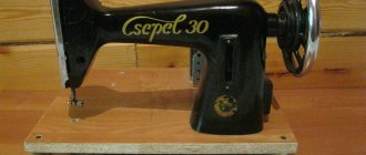
The record player was mercilessly dismantled into pieces.
All that's left
Of the entire set, only the transformer, control circuit, motor and pitch control were left, which, using a conventional strobe system, can be used to regulate the rotation speed.
The body was originally conceived as multi-layered, with layers of anti-vibration material, for which the bike was chosen, thin 3 mm strips between 3 cm layers of wood. There were 6 layers in total.
First try on layers of wood
Usually cases are glued together, but here I came across a choice: fill the anti-vibration layers with glue, thereby killing the very idea of a multi-component case, or go for a non-glued case. The second one won, as a result of which the body is tied together with 6 ties, which, together with the overlapping arrangement of the layers, makes it completely monolithic.
Fastening layers with a cut-out shaft for the engine
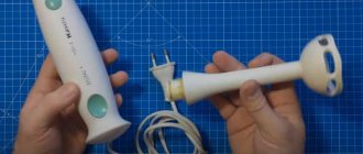
After processing the case with a file and a grinder, the electronics with the motor were mounted inside the case. The main problem was the complete separation of the engine and the body, if possible of course. For this purpose, legs were fashioned from Fimo plastic, which after baking become quite hard, but tend to compress like very hard rubber, thereby providing compensation for microvibrations that occur during rotation.
Next, the position of the engine was aligned relative to the housing using a digital micrometer so that the distance between the disk and the surface was minimal. At the moment it is approximately 2.5mm.
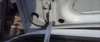
Rear control electronics housing
For the first fitting, I used what was at hand, a brass plate for attaching controls, painted black.
Control unit during fitting process
After everything was assembled, control over the rotation speed was ensured and the control unit was mounted to a first approximation, all that remained was to find a tonearm, come up with a mounting system and try the device in action.
Output Tone
The sequence 0x53 0xEF 0x6E n generates a sine wave that is sent to the output of the device. Parameter n can take values from 48 to 119. The parameters of the test signal are determined by the formulas:
And tables:
The authors hope that this article has paid enough attention to introducing the features of MP3 design.
A few words about directly turning on the VS1001k. As shown in Fig. 5, VS1001k requires 8 microcontroller I/O to control.
With some restrictions, this number can be reduced to 6, as shown in Fig. 6.
For this scheme to work, three conditions must be met:
- MISO and GIO2 must be programmed as inputs, the rest as outputs;
- when SPI is in inactive state, SPI timing should be as shown in the waveform (Figure 7);
- If the SPI bus is not available, but the microcontroller is fast enough, the general inputs and outputs of the microcontroller can be used to organize the MISO, MOSI and SCK signals.
In this circuit, GIO1 performs bus selection. If it is set to 1, XCS is not active and the SCK clock signal is applied via an AND gate to the DCLK input. Thus, the data is sent to the SDI bus. When GIO1 is set to 0, XCS is enabled and DCLK clocking is stopped. The data now arrives on the SCI bus.
For example, you want to set the volume level to -2 dB for the left channel and -3.5 dB for the right channel. To do this, we must write 0x0407 to the VOL register [1, page 50]:
- activate the SCI interface by setting GIO1 to 0;
- write four bytes (0x2, 0xb, 0x4, 0x7) to SCI;
- We finish transmitting data on the SCI bus by setting GIO1 to 1.
To receive data via the SCI bus, in particular to read the contents of the VOL register, you must:
- activate the SCI interface, GIO1 - to 0;
- write two bytes (0x3, 0xb) to SCI;
- write one byte with any content to SCI. Read the contents of the microcontroller's MISO register, which now contains the eight most significant bits of the result;
- write one byte with any content to SCI. Read the contents of the microcontroller's MISO register, which now contains the eight least significant bits of the result;
- combine the most significant and least significant bits to produce a 16-bit word;
- finish data exchange on the SCI bus, GIO1 - to 1.
To send MP3 data to the VS1001k, you need to use the following algorithm:
- wait for DREQ (1) to be activated;
- activate DCLK, GIO - to 1.
- for each byte we do the following: set BSYNC to 1;
- activate transmission via SPI;
- wait until at least the first bit of data has been sent, but the last bit of data has not;
- set BSYNC to 0;
- We wait for the end of the SPI cycle of the microcontroller to complete the procedure.
Three signals (from top to bottom) are shown in Fig. 7: DCLK (yellow), SDATA (blue) and BSYNC (pink). BSYNC is active first. Data is sent and read by the VS1001k on the edge of the DCLK clock signal. The transmitted number shown on the waveform is 0b01000101 or 0x45. The clock frequency used is 1 MHz because this is the maximum possible value that the microcontroller used can offer.
On the oscillogram Fig. 8. Sending a SDI test command is demonstrated. Eight bytes are transferred here: 0x45 0x78, 0x69, 0x74, 0x0, 0x0, 0x0, 0x0. This sequence tests the sine wave output of the VS1001k [1, page 35]. Please note that the delay between successive bytes is due to the low performance of the control microcontroller and is not needed for the VS1001k itself.
In conclusion, I would like to note that the use of the VS1001k is not limited to creating an MP3 player. The VS1001k can also be useful for creating any household devices and high-tech toys with speech capabilities.
It must be very difficult to put everything together and launch it? You need to learn Linux, right?
Firstly, when you assemble something that works from different components with your own hands, it’s incredibly exciting. Secondly, it is economical, yes, you can already buy good streamers for $399, $999 or $9000, but this is not sporty.
Thirdly, you create a flexible constructor, in which you can improve the clock generator, or install a different player, or organize file storage differently, or connect a new stimming service (for example, Spotify) - with branded sources it all depends on the manufacturer, with your own source you can do whatever you want. And finally, it’s not difficult - the complexity ranges from simply snapping on an expansion board to a little soldering. Well, Linux itself is not so scary. Installing a special audiophile Linux OS on it is also easy. Further settings and use will not require you to know secret commands. It will take time, a little attention, but you can do it!
Debugging kit
In the VS1001 KIT, shown in Fig. 9, to solve this problem, a USB controller PDIUSB12 from Philips was used, although in domestic conditions it is easier to use FT245BM microcircuits from FTDI or USBN9603 from National Semiconductor. The debug kit's printed circuit board also contains the XCR3064XL FPGA from Xilinx, whose main task is to generate the BSYNC signal - byte synchronization for the VS1001k. But this task, as indicated in the technical documentation, can also be successfully performed by a control microcontroller.
In addition to the already described components, the debugging kit contains a USB-B connector for connecting to a PC, a connector for connecting an 8 or 16 MB MMS card (where MP3 files are recorded), 5 control buttons (volume up/down, rewind, pause), headphone jack. The board can operate as an MP3 player via USB or stand-alone (requiring external power supply +5... +7 V). The VS1001 KIT also comes with a floppy disk with software, which includes complete technical documentation for the chip, drivers for Windows 98/2000 and instructions for programming the USB driver.
Future program template
Before writing basic functions, it is useful to initialize the display and keyboard. I already talked about the display above, but the keyboard with four by four buttons was left over from the phone layout.
The source code below contains standard header files, peripheral initialization functions, display and keyboard initialization functions, and at the end the output of the Hello world line.
Continuation is available only to members
Option 1. Join the “Xakep.ru” community to read all materials on the site
Membership in the community during the specified period will give you access to ALL Hacker materials, allow you to download issues in PDF, disable advertising on the site and increase your personal cumulative discount! More details
Why connect USB
Since the 70s of the last century, music has been heard from cars. At first, such a luxury as a radio in a car was not available to everyone. Only representative brands, for example Volga, could boast of it. The industry did not stand still, and soon the radio was equipped with a cassette recorder, and then began to support disks and even flash cards.
Motorists whose iron horse does not have a receiver that meets all modern requirements should not be upset. Installing USB into a standard radio is easy and does not require special skills. Almost anyone can cope with this task.
The input we are interested in allows you to listen to music from a flash drive (standard 2.0) connected to the audio equipment, if the car has a radio without USB and aux. It is convenient and in demand. Does not distract the driver from driving, unlike the situation when a telephone is connected to the radio.
Are you a car driver?! Then you can take this simple test and find out. Go to test »