Of all the ideas that the engineer and physicist Nikola Tesla worked on, and this list included alternating current, radio, and remote control (and this was at the end of the 19th century), the most fantastic and difficult to implement was the transmission of electrical energy without wires. And the point is not that the Serbian inventor did not know how to implement his project. The idea of wireless electricity, like the electric motor created during the era of rapid development of the oil industry, was not appreciated and did not receive support from investors and the scientific community. Decades later, when electrical appliances have become an integral part of our lives, wireless power transmission (WPT) is once again exciting the minds of engineers around the world. What results have already been achieved, and what methods are used today?
“Once this is done, you can go anywhere in the world—to the top of a mountain overlooking your farm, to the Arctic, or to the desert—and install small pieces of equipment that will give you heat for cooking and light for reading. This equipment fits in a small bag, like a regular suitcase. In the coming years, cordless lights will be as common on farms as conventional electric lights in our cities.”
Nikola Tesla, The American Magazine, April 1921
What it is?
The coil is a transformer. The purpose of the device is to increase current parameters to enormous heights (up to millions of volts). Main Goal: Maximize AC frequency. Ideally, the same return coil should be placed at the energy receiving point, which will resonate with the device, allowing energy to be transferred over a distance.
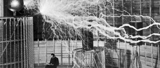
Contactless energy transfer through a Tesla coil
Let's take a closer look at how a Tesla coil works. First, let’s swing - it’s not immediately clear what’s swinging in the coil. Direct current, which Edison used in his inventions, is expensive to produce. This energy has a pronounced vector of movement. Alternating current constantly changes the parameters of electricity: voltage and current. This is called electrical current fluctuations.
It is interesting that the basic laws of oscillation of an electric current and a mechanical pendulum coincide. Interestingly, there is also a resonance effect for electricity. When the frequencies of the two electric fields coincide, the amplitude of the oscillations increases. According to Tesla's idea, after the coils resonate, an electric current should appear in the receiver.
In fact, the receiver was never invented. The Tes coil is used as a reference, on it you can see the flow: in other words, the electric arc, the current discharge, artificial lightning and study the wireless transmission of electricity.
Wireless charging has low efficiency
Today, there are three main power options for Qi wireless charging: 5 W, 7.5 W, 10 W. For comparison, the most common wired ones are 5 W, 10 W and 18 W.
The efficiency of wired power supplies that convert alternating current into direct current with specified parameters balances in the range from 50 to 85%. The rest is released by heat and is expressed by heating the elements of the electrical circuit.
The minimum condition for Qi to work with at least 5 W is a 10 W charger. Otherwise, nothing will work, charging will not work.
At the same time, to operate Qi with a power of 10 W, you need a power supply with support for QC 3.0 at 18 W or more powerful (it is often suggested to use a PD at 24 W).
The conversion efficiency is only 55%.
The transmission itself from the charger to the device is also a source of loss: the phone on average receives 4.2 W out of 5W (85% efficiency) and 9.1W out of 10W (about 90% efficiency).
From 18 W, make 9.1 W with an efficiency of 50% - is this now called “green, economical energy”?
Are there really no better technologies? Eat. Theoretically, the problem is simple: increase the voltage, reduce the current, reduce losses.
Only in electronics the battery is 4.35 V , so you will have to equip your smartphone with a step-down converter. Which must be calculated
- for specific charging parameters
- with voltage reserve
- and have large losses due to the conversion and the characteristics of the transistors used for it
High-power wireless interfaces actively promoted by Xiaomi and other Chinese brands offer higher currents.
Due to this, as well as expensive electronics (and a specific distribution of costs), they manage to achieve an efficiency of up to 55-70%.
However, they require high-power Power Delivery current sources with a power of 65 W and above, which themselves have quite high losses.
Therefore, most often manufacturers complete Qi-charging with its own power supply. As a result, the total cost of an accessory on the free market can reach 20-40% of the cost of the gadget itself. There is nothing to buy separately. So why, if most likely with a new smartphone you will have to buy a more powerful device?
Basic elements of an electricity generating plant
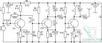
Two-element installation: oscillating and receiving. The first element is a Tesla transformer, which is powered by the IR2153 chip. The Kacher will operate at 230 kilohertz, running on a 23 kilohertz chip. There will be 2 field-effect transistors at the output. The coil is wound with 0.35 mm copper wire. 950 rpm. Almost all the details are there. The only drawback is the diet. In the following video you can see how the device turned out. This Chinese store sells ready-made rolls.
The other part of the diagram is more complex. It will be more expensive. Rare ferrites are used. But the game is worth the candle. The circuit completely does not correspond to the usual concepts of physics and electronics.
Each device needs its own charger
The same problem with the positioning of electromagnetic coils ultimately leads to the next one - the lack of a uniform standard in the industry.
The companies agreed to use low-current Qi technology and unified the devices. But either Samsung or Xiaomi release models that do not work with other people’s chargers at full speed.
Xiaomi's high-power wireless charging, introduced a couple of months ago, only works when it hits the base exactly.
And it quickly charges the battery only up to 50%, subsequently reducing the power from 80 to 20 W. Moreover, even at maximum “speed” the efficiency is only 65 W.
This charger does not work “at low speed” with other smartphones - the coils are of a different size. For the same reason, standard Qi-chargers “swing” with the corresponding Mi 11 Ultra only up to 10 W.
A single process standard is needed, otherwise the infrastructure will only work for one manufacturer.
Even with smartphones, this is not beneficial to the user. And what about cars?
Especially when existing prototypes from Momentum Dynamic promise incredible, impossible 100% efficiency?
History of development
The development of remote wireless transmission of electricity is associated with advances in radio technology, since both processes are of the same nature. Inventions in both areas are associated with the study of the method of electromagnetic induction and its effect on the generation of electric current.
In the morning of 1820, Ampere discovered the law of interaction of currents, which was that if a current flows in the same direction through two closely located conductors, then they attract each other, and if they are in different directions, they repel.
M. Faraday in 1831 established through experiments that an alternating magnetic field (which changes size and direction over time) created by the flow of electric current induces (induces) currents in adjacent conductors. Those have wireless power transmission. We discussed Faraday's law in detail in a previous article.
So, J.C. Maxwell 33 years later, in 1864, translated Faraday’s experimental data into mathematical form; the same Maxwell equations are fundamental in electrodynamics. They describe how electric current and electromagnetic field are related.
The existence of electromagnetic waves was confirmed in 1888 by G. Hertz during his experiments with a spark emitter with a switch on a Ruhmkorff coil. In this way, electromagnetic waves with a frequency of up to half a gigahertz were created. It is worth noting that these waves could be received by multiple receivers, but they must be tuned in resonance with the transmitter. The range of the plant was about 3 meters. When a spark occurred in the transmitter, the same spark occurred in the receivers. In fact, these are the first experiments in wireless power transmission.
The famous scientist Nikola Tesla conducted extensive research. He studied high voltage and frequency alternating current in 1891. As a result, the following conclusions were made:
For each specific purpose, the installation must be set to the appropriate frequency and voltage. In this case, high frequency is not a prerequisite. The best results were obtained at a frequency of 15-20 kHz and a transmitter voltage of 20 kV. An oscillatory capacitor discharge was used to produce high frequency current and voltage. In this way, both electricity can be transmitted and light can be produced.
During his speeches and lectures, the scientist demonstrated the glow of lamps (electron tubes) under the influence of a high-frequency electrostatic field. In fact, Tesla's main conclusions were that even with resonant systems, it is impossible to transfer much energy using an electromagnetic wave.
In parallel, a number of scientists were engaged in similar research until 1897: Jagdish Boche in India, Alexander Popov in Russia and Guglielmo Marconi in Italy.
Each of them contributed to the development of wireless energy transmission:
- J. Bosch ignited gunpowder in 1894, transmitting electricity over a distance without wires. He did this during a demonstration in Calcutta.
- A. Popov transmitted the first message using Morse code on April 25 (May 7), 1895. In Russia today, May 7, is still Radio Day.
- In 1896, G. Marconi in Great Britain also transmitted a radio signal (Morse code) to a distance of 1.5 km and then 3 km over Salisbury Plain.
It is worth noting that Tesla’s work, underestimated in its time and lost for centuries, surpassed the work of his contemporaries in terms of parameters and power. At the same time, it was in 1896 that his devices transmitted a signal over long distances (48 km), but, unfortunately, it was a small amount of electricity.
And in 1899 Tesla came to the conclusion:
The failure of the induction method seems enormous in comparison with the method of exciting the charge of the earth and air.
This finding would lead to other research: in 1900 he was able to power a lamp from a coil in the field, and in 1903 the Vandercliffe Tower on Long Island was launched. It consisted of a transformer with a grounded secondary winding and a spherical copper dome on top. With his help, it turned out that 200 50-watt lamps were lit. At the same time, the transmitter was 40 km away. Unfortunately, this research was stopped, funding was suspended, and free wireless transmission of electricity was not economically viable for business people. The tower was destroyed in 1917.
Story
Wireless power transmission, as an alternative to the transmission and distribution of electrical lines, was first proposed and demonstrated by Nikola Tesla. In 1899, Tesla presented the wireless transmission of power to a field of fluorescent lamps located twenty-five miles from the power source without the use of wires. But at the time, it was cheaper to wire 25 miles of copper wire rather than build the special power generators that Tesla's expertise required. He was never given a patent, and the invention remained in the recesses of science.
While Tesla was the first person to demonstrate the practical capabilities of wireless communication back in 1899, today there are very few devices on sale, such as wireless brushes, headphones, phone chargers and the like.
Coil device
The Tesla transformer, the diagram of which will be presented below, consists of two coils, a toroid, a protective ring and, of course, grounding.
TC desktop sketch
Each element must be considered separately:
- secondary winding. For winding, enameled copper wire with 800 turns is used. Therefore, the coils do not unwind and are not scratched;
- grounding If you turn on an ungrounded coil, streamers (current discharges) will not enter the air, but will create a closed circuit.
- the primary winding is located at the bottom. It is supplied with power. It must be grounded. Made of low strength metal;
- toroid. This element reduces the resonant frequency, stores energy and increases the operating range.
- protective ring. This is an open ring made of copper wire. Set if the length of the braid is greater than the length of the secondary winding;
TC drawing
Security measures
Once your CT is assembled, there are a few precautions to take before launching. First you need to check the wiring in the room where you plan to connect the transformer
Secondly, check the insulation of the windings.
It is also worth remembering the simplest precautions. The average voltage of the secondary winding is 700A, 15A per person is already deadly
In addition, it is worth moving all electrical appliances away; if they get into the range of the coil, they can burn out.
CT is a revolutionary discovery of its time, which is underestimated today. Today the Tesla transformer is used only for the entertainment of home electricians and in light displays. You can make a coil yourself using available tools. You will need a PVC pipe, several hundred meters of copper wire, a couple of meters of copper tubing, a transistor and a couple of resistors.
Microwave
Is there really no other truly effective way to wirelessly transmit electricity? Yes, and this was invented before children tried and played Star Wars.
It turns out that special microwaves 12 cm long (frequency 2.45 GHz) are transparent to the atmosphere and do not interfere with their propagation.
No matter how bad the weather, you will only lose five percent when broadcasting using microwaves! But to do this, you must first convert electrical current into microwaves, then capture them and return them to their original state.
Scientists solved the first problem a long time ago. For this purpose, they came up with a special device and called it a magnetron.
Moreover, it was done so professionally and safely that today each of you has such a device at home. Go to the kitchen and look at your microwave.
Inside is the same magnetron with an efficiency of 95%.
But how to do the reverse transformation? And here two approaches have been developed:
- American
- Soviet
In the United States in the 1960s, scientist W. Brown invented an antenna that performed the required task. That is, it converted the incident radiation back into electric current.
He also gave it his name - rectenna.
After the invention, experiments followed. And in 1975, using a rectenna, up to 30 kW of power was transmitted and received over a distance of more than a kilometer. Transmission losses were only 18%.
Nearly half a century later, this experience has never gotten old. It would seem that the method has been found, so why weren’t these rectennas thrown into the masses?
And here again the shortcomings appear. Rectennas are assembled on the basis of miniature semiconductors. Normal operation for them is to transmit power of only a few watts.
And if you want to transmit tens or hundreds of kilowatts, then get ready to assemble giant panels.
And here the same insoluble difficulties arise. Firstly, this is re-radiation.
Because of this, you will not only lose some of your energy, but also will not be able to approach the panels without losing your health.
The second headache is the instability of semiconductors in the panels. It is enough to burn one due to a slight overload, and the rest fail like an avalanche, like matches.
In the USSR everything was somewhat different. It was not for nothing that our military was confident that even in the event of a nuclear explosion, all foreign equipment would immediately fail, but Soviet equipment would not. The whole secret is in the lamps.
At Moscow State University, two of our scientists, V. Savin and V. Vanke, developed the so-called cyclotron energy converter. It has decent dimensions, as it is assembled using lamp technology.
Externally, it is something like a tube 40 cm long and 15 cm in diameter. The efficiency of this lamp unit is slightly lower than that of an American semiconductor element - up to 85%.
But unlike semiconductor detectors, a cyclotron energy converter has a number of significant advantages:
- reliability
- high voltage
- overload resistance
- without re-irradiation
- low production cost
However, despite all of the above, it is the methods of implementing semiconductor design that are considered advanced throughout the world. There is a fashion element here too.
After the first appearance of semiconductors, everyone began to sharply abandon tube technology. But practical tests show that this is often the wrong approach.
Of course, no one is interested in cell phones or 20-kilogram tube computers that take up entire rooms.
But sometimes only proven old methods can help us in hopeless situations.
As a result, today we have three options for wireless power transmission. The first one considered is limited by both distance and power.
But this is enough to charge the battery of a smartphone, tablet or something larger. Although the efficiency is low, the method still works.
Laser technology is only good in space. On the surface of the earth this is not very effective. True, when there is no other choice, you can use it.
But microwave ovens give free rein to the imagination. With their help you can transfer energy:
- on earth and in space
- from the surface of the earth to a spacecraft or satellite
- and vice versa, from a satellite in space it returns to Earth
Transferring energy through coils
The most easily implemented method is to use inductors.
The principle here is very simple. Take 2 coils and place them close to each other. One of them is supplied with power. The other plays the role of receiver.
When the current in the power source is adjusted or changed, the magnetic flux in the second coil automatically changes as well. As the laws of physics say, in this case an EMF will arise and it will directly depend on the rate of change of this flow.
It would seem that everything is simple. But the shortcomings spoil the whole rosy picture. Three disadvantages:
- low power
Using this method, you will not transfer large volumes and will not be able to connect powerful devices. If you try to do this, you will simply melt all the windings.
- short distance
Don't even think about transmitting electricity over tens or hundreds of meters here. This method has limited effect.
To physically understand how bad things are, take two magnets and figure out how far apart they need to be before they stop attracting or repelling each other. The efficiency of coils is approximately the same.
You can, of course, get creative and ensure that these two elements are always close to each other. For example, an electric car and a special charging road.
But how much will the construction of such highways cost?
- low efficiency
Another problem is low efficiency. It does not exceed 40%. It turns out that you will not be able to transmit a lot of electrical energy over long distances in this way.
The same N. Tesla pointed out this back in 1899. Later he switched to experiments with atmospheric electricity, hoping to find a clue and solution to the problem in it.
However, no matter how useless all these things may seem, with their help you can still organize beautiful light and music performances.
Or recharge equipment much larger than phones. For example electric bicycles.
The most promising directions
Wireless electricity is constantly being studied by many physicists; the most promising directions in this area are considered, which include:
- Charge mobile devices without connecting to a cable;
- The implementation of power supply for unmanned aerial vehicles is an area that will be in great demand in both the civilian and military industries, since such devices have recently been used for various purposes.
The same procedure for remote data transfer without the use of wires was once considered a breakthrough in physical and energy research; now it surprises no one and has become available to everyone. Thanks to modern developments in technology and developments, transporting electricity by this method is becoming a reality and can be implemented.
The wait is relatively short. If the Japanese keep their promises, in 2022 all household appliances, computers and portable devices will be freed from the yoke of wires that have enslaved humanity. The buyer will only have to bring home, for example, a new TV, hang it on the wall and start watching a movie literally right away, without thinking about which screen to hide the ugly black power cord on. Wireless energy transmitters will be built into the streets, apartments, and cafes, which will allow people to forget about dead batteries. Of course, the final implementation of such ideas will take ten years, but we have every chance for a bright future. In addition, there are already quite functional technologies. It's a pity that Nikola Tesla will not see this day...
Prospects
Research and development of electric vehicle projects are currently underway. They will move with the help of a conductor, which induces a current in the vehicle's engine.
Many innovative companies are developing a wireless method for transmitting electricity to power sources; such devices must provide power to all consumers in the same room. New routes are also a promising direction, which, thanks to a wireless source, will ensure the movement of an aircraft at a considerable distance. New materials, improved devices and much more will eventually cover all areas of human activity.
To the origins of the appearance
In 1893, an exhibition was held in Chicago. There was a demonstration of wireless lighting, in which everything was powered by fluorescent lamps. This work belonged to Nikola Tesla.
Now you can repeat the experiment - just stand with a fluorescent lamp under a high voltage line. And then it was more like a session of magic, which is why the inventor gained such popularity.
Today, not every scientist will agree that it was Tesla who came up with the idea of creating wireless electricity. They believe that his work is a refinement of an existing idea. For example, 73 years before the exhibition, Andre Ampere wrote down a law that indicates that when an electric current is used, a magnetic field is created. Eleven years later, Michael Faraday discovered the law of induction. An experiment was conducted that showed that a magnetic field generated in one conductor induces a current in the other conductor.
In 1864, all theories were united. The work belongs to James Maxwell. He came to an equation that described the electromagnetic field, as well as the connection with electric charges and currents in a vacuum.
Twenty-seven years later, Tesla modernized the wave transmitter that Hertz had invented a little earlier. He patented it as a device for radio frequency power supply.
Physics of wireless transmission of electrical energy
Wirelessly transmitting power to home devices is a new technology, but the basic principles have been known for a long time. When electricity and magnetism are involved, Maxwell's equations are still governed and transmitters send energy to receivers in the same way as other forms of wireless communication. However, wireless transmission of electricity differs from them in its main purpose, which is to transmit the energy itself, and not the information encoded in it.
Block diagram of transmitter and receiver for wireless power transmission
The electromagnetic fields involved in wireless power transmission can be quite strong, so human safety must be taken into account. Exposure to electromagnetic radiation can cause problems, and there is a possibility that fields generated by electrical energy transmitters may interfere with the operation of wearable or implanted medical devices.
Transmitters and receivers are built into devices to wirelessly transmit power, as are the batteries they will charge. Actual conversion patterns will depend on the technology used. In addition to the power transmission itself, the WPT system must provide communication between the transmitter and the receiver. This ensures that the receiver can notify the charger that the battery is fully charged. Communication also allows the transmitter to locate and identify the receiver to fine-tune the power delivered to the load and monitor battery temperature, for example.
In wireless power transmission, the choice of near-field or far-field concepts is important. Transmission technologies, the amount of energy transmitted, and distance requirements influence whether a system uses near-field or far-field radiation.
Points for which the distance from the antenna is significantly less than one wavelength are in the near field. Energy in the near-field zone does not radiate, and the oscillations of the magnetic and electric fields are independent of each other. Capacitive (electrical) and inductive (magnetic) coupling can be used to transfer energy to a receiver located in the near field of the transmitter.
Points for which the distance from the antenna is greater than about two wavelengths are in the far field (there is a transition region between the near and far fields). Far-field energy is transmitted in the form of ordinary electromagnetic radiation. Far field energy transfer is also called energy beaming. Examples of far-field transmission are systems that use high-power lasers or microwaves to transmit energy over long distances.
Transfer principles
Power generation
The latest developments by scientists from the USA and South Korea used magnetic resonance systems CMRS and DCRS. Korean technology turned out to be more advanced. It was possible to transmit electricity over 5 meters. Thanks to compact DCRS dipole coils, it is possible to power all consumers in a medium-sized room without wires.
Important! The imperfection of modern equipment significantly limits the length of the path of electricity through the air.
Despite this, scientists around the world are busy developing new technologies whose task is to transfer energy over distances of tens and hundreds of kilometers. Already today, new scientific achievements in the field of electricity delivery without wired power lines are being developed and implemented.
Technology
Principle of Inductive Coupling
Two devices, either mutually inductively coupled or magnetically coupled, are designed in such a way that the change in current when one wire induces a voltage at the ends of the other wire is produced by electromagnetic induction. This is due to mutual inductance. Inductive coupling is preferred because of its ability to operate wirelessly and because of its shock resistance.
Resonant coupling is a combination of inductive coupling and resonance. Using the concept of resonance, two objects can be made to operate independently of each other's signals.
Principle of inductive resonance coupling
As you can see from the diagram above, resonance is provided by the inductance of the coil. The capacitor is connected in parallel to the winding. Energy will move back and forth between the magnetic field surrounding the coil and the electric field around the capacitor. Here radiation losses will be minimal.
There is also the concept of wireless ionized communication.
This is also achievable, but it requires a little more effort. This method already exists in nature, but there is hardly any possibility of its implementation, since it requires a strong magnetic field, from 2.11 M/m. It was developed by the brilliant scientist Richard Walras, the developer of a vortex generator that sends and transmits thermal energy over long distances, in particular, using special collectors. The simplest example of such a connection is lightning.
Wireless methods of transmitting electricity
Energy can propagate through the network in question to virtually any non-metallic material, including but not limited to. These include solids such as wood, plastic, textiles, glass and brick, as well as gases and liquids. When a metallic or electrically conductive material (such as carbon fiber) is placed in close proximity to an electromagnetic field, the object absorbs energy from it and therefore heats up. This, in turn, affects the efficiency of the system. This is how induction cooking works, for example, the inefficient transfer of energy from the cooktop creates heat for cooking.
To create a wireless power transmission system, it is necessary to return to the origins of the topic at hand. Or, more precisely, the successful scientist and inventor Nikola Tesla, who created and patented a generator capable of receiving energy without various materialistic conductors. So, to implement a wireless system, it is necessary to assemble all the important elements and parts, as a result a small Tesla coil will be realized. This is a device that creates a high voltage electric field in the surrounding air. At the same time, there is a small input power that allows wireless transmission of energy over a distance.
One of the most important methods of energy transfer is inductive coupling. Mainly used for close combat. It differs in that when current flows through one wire, a voltage is induced at the ends of the other. Energy transfer occurs through reciprocity between two materials. A typical example is a transformer. The idea of microwave energy transfer was developed by William Brown. The entire concept involves converting AC power into RF power and transmitting it into space, and reusing the AC power for the receiver. In this system, voltage is generated using microwave energy sources. Like a klystron. And this power is transmitted to the transmitting antenna through a waveguide that protects against reflected power. And also a tuner that matches the impedance of the microwave source with other elements. The receiving part consists of an antenna. It adopts microwave power, impedance and filter matching circuit. This receiving antenna, together with the rectifier device, can be a dipole. Corresponds to an output signal similar to the sound signal of the rectifier unit. The receiving unit also consists of a similar section consisting of diodes, which are used to convert the signal into a DC warning. This transmission system uses frequencies in the range of 2 GHz to 6 GHz.
Wireless transmission of electricity using Kamara Brovin, who implemented a generator using similar magnetic oscillations. The point is that this device worked thanks to three transistors.
Using a laser beam to transmit energy in the form of light energy, which is converted into electrical energy at the receiving end. The material itself is powered directly from sources such as the sun or any electrical generator. And as a result, it realizes highly focused light. The size and shape of the beam are determined by the optics package. And this transmitted laser light is received by photovoltaic cells, which convert it into electrical signals. Typically fiber optic cables are used for transmission. As with a basic solar power system, the receiver used in laser propagation is a series of photovoltaic cells or a solar panel. In turn, they can convert inconsistent monochromatic light into electricity.
The more current sources, the less predictable the consequences
Finally, there is another unsolved physical problem: the superposition of electromagnetic fields. The more chargers and their power, the further and further their waves travel.
At some point they will begin to interact. This doesn't seem like a problem at first glance.
Exactly until someone decides to place a couple of charges next to each other, shifting the propagation vector to something sensitive to the electromagnetic field.
This “something” could be a communications device, a pacemaker, a communications station, or any other electronic device.
The problem is not that it will be affected by one source - theoretically, even powerful wireless chargers can be designed so as not to interfere with electronics.
But when waves superimpose on each other, an unknown value will be obtained that is difficult to predict. Is this risk necessary?
By the way, judging by rumors, this is what “killed” the AirPower wireless charging from Apple, which could carry 32 coils (low-current!).
“Over time, these harmonics add up and very powerful signals appear in the air,” he explains. “And this can be difficult - for example, such radiation could stop someone’s pacemaker if it was powerful enough. Or short-circuit someone’s hearing aid.”
William Lumpkins, Technical Vice President, O&S Services
If your Apple device was causing harmonics to fly out in all directions, your AirPower may have failed US or EU regulatory tests.
We get energy with and without coils
We try to remove etheric energy in two ways. At first, the transformer operates autonomously, without additional coils. On the left is the consumption voltage, on the right is the current. Voltage is about 11 volts, current is 1.8. Now we connect two identical coils. The removal tubes are inserted into their middle. The lights at their output light up. Those used in a refrigerator are 220 volts, 15 watts. The reels are wound in the same way as the pitcher. All ends of the bulbs will go into the ground. Let's see how the parameters change.
7. Information about frequency measurement on the board. How did this happen? Included in the secondary winding. He went from the coil, passed through the ferrite, then wound 3 turns of ordinary wire around the ring and the findings went to the oscilloscope. I started this. The limit is 1 microsecond. Voltage limit 1 volt. We are looking.
Real projects today
Of all that the electrical market offers today, this concerns wireless power transmission, chargers for smartphones, and electric toothbrushes. They use the principle of electromagnetic induction.
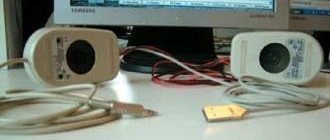
Contactless smartphone charging
The aviation industry has begun mass production of unmanned aerial vehicles with wireless power transmission. The small microwave rectenna helicopter can fly up to 15 meters above the ground. Drones have appeared that can fly in the line of sight of a laser beam.
Chinese home appliance manufacturer Haier Group has been producing wireless LCD TVs since 2010.
Transmission of electricity without wires - from the beginning to the present day
Wireless transmission of electricity is a method of transmitting electrical energy without the use of conductive elements in an electrical circuit.
At the end of the 19th century, the discovery that electricity could make a light bulb glow sparked an explosion of research to find the best way to transmit electricity.
Wireless energy transfer was actively studied at the beginning of the 20th century, when scientists paid great attention to finding various ways to wirelessly transfer energy. The goal of the research was simple - to generate an electric field in one place so that it could then be detected by instruments at a distance. At the same time, attempts were made to supply energy at a distance not only to highly sensitive sensors for recording voltage, but also to significant energy consumers. So, in 1904 at the exhibition St. Louis World's Fair was awarded a prize for successfully starting a 0.1 horsepower aircraft engine at a distance of 30 m.
The gurus of “electricity” are known to many (William Sturgeon, Michael Faraday, Nicolas Joseph Callan, James Clerk Maxwel, Heinrich Hertz, Mahlon Loomas, etc.), but few people know that the Japanese researcher Hidetsugu Yagi used an antenna of his own design to transmit energy. In February 1926, he published the results of his research, in which he described the structure and method of tuning the Yagi antenna.
Note: I deliberately did not mention Nikola Tesla: a lot has been written by many.
Very serious work and projects were carried out in the USSR in the period 1930-1941 and in parallel in Drittes Reich. Naturally, mainly for military purposes. Naturally, mainly for military purposes: defeating enemy personnel, destroying military and industrial infrastructure, etc. In the USSR, serious work was also carried out on the use of microwave radiation to prevent surface corrosion of metal structures and products. But that's a different story. Again we have to climb into the dusty attic.
One of the greatest Russian physicists of the last century, Nobel Prize laureate, Academician Pyotr Leonidovich Kapitsa devoted part of his creative biography to the study of the prospects for using microwave oscillations and waves to create new and highly efficient energy transmission systems. In 1962, in the preface to his book, he wrote
“... I want to remind you that electrical engineering, before coming to the service of the energy sector, in the last century dealt extensively only with issues of telecommunications (telegraph, signaling, etc.). It is likely that history will repeat itself: electronics are now used primarily for radio communications, but their future lies in solving the biggest energy problems."
.
Of the long list of fantastic technical ideas realized in the twentieth century, only the dream of wireless transmission of electrical energy continued to remain unrealized. Detailed descriptions of energy beams in science fiction novels tantalized engineers with their obvious need, yet the practical difficulty of implementing them. But the situation gradually began to change for the better.
In 1964, microwave electronics expert William C. Brown first tested a device (a helicopter model) capable of receiving and using microwave beam energy in the form of direct current, thanks to an antenna array consisting of half-wave dipoles, each loaded with highly efficient Schottky diodes.
In 1964, William C. Brown demonstrated his helicopter model on the CBS program Walter Cronkite News, which received sufficient energy for flight from a microwave emitter.
Already by 1976, William Brown transmitted a microwave beam of 30 kW power over a distance of 1.6 km with an efficiency exceeding 80%.
Tests were carried out in the laboratory and commissioned by Raytheon Co. Read in detail (in English): Microwave Power Transmission - IOSR Journals The microwave powered Helicopter. William C. Brown. Raytheon Company.
In 1968, American space research specialist Peter E. Glaser proposed placing large solar panels in geostationary orbit, and transmitting the energy they generate (5-10 GW) to the surface of the Earth with a well-focused beam of microwave radiation , then convert it into direct or alternating current energy of technical frequency and distribute it to consumers.
This scheme made it possible to use the intense flux of solar radiation existing in geostationary orbit (~ 1.4 kW/sq.m.) and transmit the resulting energy to the Earth’s surface continuously, regardless of the time of day and weather conditions [2-12]. Due to the natural inclination of the equatorial plane to the ecliptic plane with an angle of 23.5 degrees, a satellite located in a geostationary orbit is illuminated by the flow of solar radiation almost continuously, with the exception of short periods of time near the days of the spring and autumn equinoxes, when this satellite falls into the Earth's shadow. These periods of time can be accurately predicted, and in total they do not exceed 1% of the total length of the year.
The frequency of electromagnetic oscillations of the microwave beam must correspond to those ranges that are allocated for use in industry, scientific research and medicine. If this frequency is chosen to be 2.45 GHz, then meteorological conditions, including thick clouds and intense precipitation, have virtually no effect on the efficiency of power transmission. The 5.8 GHz band is attractive because it offers the opportunity to reduce the size of the transmit and receive antennas. However, the influence of meteorological conditions here requires additional study.
The current level of development of microwave electronics allows us to speak of a fairly high efficiency of microwave energy transfer by a microwave beam from geostationary orbit to the Earth's surface - about 70-75%. In this case, the diameter of the transmitting antenna is usually chosen to be 1 km, and the ground rectenna has dimensions of 10 km x 13 km for a latitude of 35 degrees. A SCES with an output power level of 5 GW has a radiated power density at the center of the transmitting antenna of 23 kW/sq.m., and at the center of the receiving antenna – 230 W/sq.m.
Various types of solid-state and vacuum microwave generators for the SKES transmitting antenna were investigated. William Brown showed, in particular, that magnetrons, well-developed by industry, intended for microwave ovens, can also be used in transmitting antenna arrays of SKES, if each of them is equipped with its own negative feedback circuit in phase with respect to the external synchronizing signal (so called Magnetron Directional Amplifier - MDA).
Rectenna is a highly efficient receiving-converting system, however, the low-voltage diodes and the need for their serial switching can lead to avalanche-like breakdowns. A cyclotron energy converter can largely eliminate this problem.
The SKES transmitting antenna can be a back-reradiating active antenna array based on slot waveguides. Its rough orientation is carried out mechanically; for precise guidance of the microwave beam, a pilot signal is used, emitted from the center of the receiving rectenna and analyzed on the surface of the transmitting antenna by a network of appropriate sensors.
From 1965 to 1975 A scientific program led by Bill Brown was successfully completed, demonstrating the ability to transmit 30 kW of power over a distance of more than 1 mile with an efficiency of 84%.
In 1978–1979 in the United States, under the leadership of the Department of Energy (DOE) and NASA (NASA), the first government research program aimed at determining the prospects of SCES was carried out.
In 1995–1997, NASA again returned to discussing the prospects of SCES, based on the technological progress achieved by that time.
Research continued in 1999–2000 (Space Solar Power (SSP) Strategic Research & Technology Program).
The most active and systematic research in the field of SCES was carried out by Japan. In 1981, under the leadership of Professors M. Nagatomo and S. Sasaki at the Space Research Institute of Japan, research began on the development of a prototype SCES with a power level of 10 MW, which could be created using existing launch vehicles. The creation of such a prototype allows one to accumulate technological experience and prepare the basis for the formation of commercial systems.
The project was named SKES2000 (SPS2000) and received recognition in many countries around the world.
In 2008, Marin Soljačić, assistant professor of physics at the Massachusetts Institute of Technology (MIT), was awakened from a sweet sleep by the persistent beeping of his cell phone. “The phone didn’t stop talking, demanding that I put it on charge,” Soljacic says. Tired and not about to get up, he began to dream that the phone, once at home, would start charging on its own
.
This is how WiTricity and WiTricity corporation appeared.
In June 2007, Marin Soljačić and several other MIT researchers reported the development of a system in which a 60 W light bulb was supplied from a source located 2 m away, with an efficiency of 40%.
According to the authors of the invention, this is not a “pure” resonance of coupled circuits and not a Tesla transformer with inductive coupling.
The radius of energy transmission today is a little more than two meters, in the future - up to 5-7 meters. In general, scientists tested two fundamentally different schemes. 1. In an induction coil or electrical transformer, which has a metal or air core, the transfer of energy is carried out by a simple electromagnetic connection called magnetic induction.
Using this method, transmitting and receiving energy became feasible over a considerable distance, but to obtain significant voltage in this way it was necessary to place the two coils very close. 2. If magnetic resonance coupling is used, where both inductors are tuned to mutual frequency, significant energy can be transferred over a considerable distance. Similar technologies are being feverishly developed by other companies: Intel demonstrated its WREL technology with energy transfer efficiency of up to 75%. In 2009, Sony demonstrated the operation of a TV without a network connection. There is only one circumstance that is alarming: regardless of the transmission method and technical tricks, the energy density and field strength in the premises must be high enough to power devices with a power of several tens of watts. According to the developers themselves, there is no information yet on the biological effects of such systems on humans. Considering the recent emergence and different approaches to the implementation of energy transfer devices, such research is yet to come, and the results will not appear soon. And we can judge their negative impact only indirectly. Something will again disappear from our homes, such as cockroaches.
In 2010, Haier Group, a Chinese home appliance manufacturer, unveiled its unique product at CES 2010 - a completely wireless LCD TV based on the research of Professor Marin Soljacic on wireless power transmission and wireless home digital interface (WHDI).
In 2012-2015 Engineers at the University of Washington have developed technology that allows Wi-Fi to be used as an energy source to power portable devices and charge gadgets. The technology has already been recognized by Popular Science magazine as one of the best innovations of 2015. The ubiquity of wireless data transmission technology in itself has produced a real revolution. And now it’s the turn of wireless energy transmission over the air, which developers from the University of Washington called PoWiFi (from Power Over WiFi).
During the testing phase, the researchers were able to successfully charge small-capacity lithium-ion and nickel-metal hydride batteries. Using the Asus RT-AC68U router and several sensors located at a distance of 8.5 meters from it. These sensors convert the energy of the electromagnetic wave into direct current with a voltage of 1.8 to 2.4 volts, which is necessary to power microcontrollers and sensor systems. The peculiarity of the technology is that the quality of the working signal does not deteriorate. You just need to reflash the router, and you can use it as usual, plus supply power to low-power devices. In one demonstration, a small, low-resolution surveillance camera located more than 5 meters from the router was successfully powered. Then the Jawbone Up24 fitness tracker was charged to 41%, which took 2.5 hours.
To tricky questions about why these processes do not negatively affect the quality of the network communication channel, the developers answered that this becomes possible due to the fact that the re-flashed router, during its operation, sends energy packets through channels unoccupied by information transmission. They came to this decision when they discovered that during periods of silence, energy simply flows out of the system, but it can be used to power low-power devices.
During the research, the PoWiFi system was placed in six houses, and residents were asked to use the Internet as usual. Load web pages, watch streaming videos, and then tell us what's changed. As a result, it turned out that network performance did not change at all. That is, the Internet worked as usual, and the presence of the added option was not noticeable. And these were only the first tests, when a relatively small amount of energy was collected over Wi-Fi
.
In the future, PoWiFi technology could well serve to power sensors built into household appliances and military equipment in order to control them wirelessly and carry out remote charging/recharging.
Current is the transfer of energy for UAVs (most likely using PoWiMax technology or from the radar of the carrier aircraft):
→ LOCUST - Swarming Navy Drones → The Pentagon successfully tested a swarm of 103 drones → Intel operated the drone show during Lady Gaga's Super Bowl halftime performance
For a UAV, the negative from the inverse square law (isotropically radiating antenna) is partially “compensated” by the antenna beamwidth and radiation pattern:
After all, an aircraft's radar can produce 17 kW of EMP energy in a pulse.
This is not cellular communication - where the cell must provide 360-degree communication to the end elements. Let's assume this variation: The carrier aircraft (for Perdix) this F-18 has (now) AN/APG-65 radar:
maximum average radiated power of 12000 W
or in the future it will have AN/APG-79 AESA: in a pulse it should produce EMP energy under 15 kW
This is quite enough to extend the active life of Perdix Micro-Drones from the current 20 minutes to an hour, and maybe more.
Most likely, an intermediate Perdix Middle drone will be used, which will be irradiated at a sufficient distance by the fighter's radar, and it, in turn, will “distribute” energy to the younger brothers of the Perdix Micro-Drones via PoWiFi/PoWiMax, while simultaneously exchanging information with them (flight, aerobatic, target tasks, swarm coordination).
Perhaps soon it will come to charging cell phones and other mobile devices that are within the range of Wi-Fi, Wi-Max or 5G?
Afterword: 10-20 years, after the widespread introduction of numerous electromagnetic microwave emitters into everyday life (Mobile phones, Microwave ovens, Computers, WiFi, Blu tools, etc.), suddenly cockroaches in big cities suddenly turned into a rarity! Now the cockroach is an insect that can only be found in a zoo. They suddenly disappeared from the homes they once loved so much.
COCKROACHES CARL! These monsters, leaders of the list of “radioresistant organisms,” shamelessly capitulated!
LD 50 is the average lethal dose, that is, the dose kills half of the organisms in the experiment; LD 100 - a lethal dose kills all organisms in the experiment.
Who's next in line?
The permissible levels of radiation from mobile communication base stations (900 and 1800 MHz, total level from all sources) in sanitary and residential areas in some countries differ markedly: Ukraine: 2.5 µW/cm².
(the most stringent sanitary standard in Europe) Russia, Hungary: 10 µW/cm². Moscow: 2.0 µW/cm². (the norm existed until the end of 2009) USA, Scandinavian countries: 100 μW/cm². The temporary permissible level (TLA) from mobile radiotelephones (MRT) for radiotelephone users in the Russian Federation is determined to be 10 μW/cm² (Section IV - Hygienic requirements for mobile land radio communication stations SanPiN 2.1.8/2.2.4.1190-03 “Hygienic requirements for placement and operation means of land mobile radio communications"). In the USA, the Certificate is issued by the Federal Communications Commission (FCC) for cellular devices whose maximum SAR level does not exceed 1.6 W/kg (and the absorbed radiation power is reduced to 1 gram of human organ tissue). In Europe, according to the international directive of the Commission on Non-Ionizing Radiation Protection (ICNIRP), the SAR value of a mobile phone should not exceed 2 W/kg (the absorbed radiation power is reduced to 10 grams of human organ tissue). More recently, in the UK, a safe SAR level was considered to be 10 W/kg. A similar picture was observed in other countries. The maximum SAR value adopted in the standard (1.6 W/kg) cannot even be confidently attributed to “hard” or “soft” standards. The standards adopted in both the USA and Europe for determining the value of SAR (all regulation of microwave radiation from cell phones, which is discussed, is based only on the thermal effect, that is, associated with heating the tissues of human organs). COMPLETE CHAOS.
Medicine has not yet given a clear answer to the question: is mobile/WiFi harmful and to what extent? What will happen to the wireless transmission of electricity using microwave technologies? Here the power is not watts and miles of watts, but kW...
Note: A typical WiMAX base station emits power at approximately +43 dBm (20 W), and a mobile station typically transmits at +23 dBm (200 mW).
Documents, photos and videos used
"JOURNAL OF RADIO ELECTRONICS" N 12, 2007 (ELECTRIC POWER FROM SPACE - SOLAR SPACE POWER PLANTS, V. A. Vanke) "Microwave electronics - prospects in space energy" V. Vanke, Doctor of Physical and Mathematical Sciences. www.nasa.gov www.whdi.org www.defense.gov www.witricity.com www.ru.pinterest.com www.raytheon.com www.ausairpower.net www.wikipedia.org www.slideshare.net www.homes .cs.washington.edu www.dailywireless.org www.digimedia.ru www.powercoup.by www.researchgate.net www.proelectro.info www.youtube.com
How wireless electricity works: induction
Despite the fact that technology has developed rapidly in recent decades, one of the most popular methods of wireless transmission of electricity is not much different from the one used by Faraday. One resonant copper coil is connected to the power source, the other acts as a receiver.
A video of wireless electricity using two coils clearly demonstrates both the simplicity of the technology and its main problem - the short range. In addition, it is impossible to transfer large amounts of energy with its help (the coils will melt), despite the fact that the efficiency is about 40% (Tesla wrote about this in 1899).
However, it cannot be said that magnetic induction has not found its application. Today the technology is actively used for the production of wireless chargers. Apple touted its wireless chargers as something revolutionary in 2022, although this new product is actually over 100 years old.
Wireless electricity: popular technologies
In addition to induction, on which manufacturers of electric vehicles and gadgets place their main bets, 3 more methods are known: laser, microwave, ultrasound. Scientists are convinced that each of these areas can develop in the future.
- Laser. Energy is transferred by converting it into a beam, which is directed to a photocell in the receiver. Large amounts of energy can be transferred this way, but these planes break up in the Earth's atmosphere, causing most (about 60%) of the energy to be dissipated. But in airless spaces the technology is quite viable. That's why space exploration companies continue to explore laser technology: in 2009, NASA even held a $900,000 competition for the WPT laser. First place was taken by Laser Motive: at 1 km and 0.5 kW of continuous transmitted power. Despite the fact that, of course, the targets reached only 10% of the energy, the experiment was considered successful.
- Microwave. Theoretically, the transmission of radio wave energy can be made directional using semiconductors or lamps (cyclotron energy converters). Semiconductors are now widely used all over the world, but when it comes to transmitting large amounts of energy, more semiconductors need to be used. This not only increases the cost of the project, but also re-radiation occurs, i.e. it is unsafe to be near such panels. But semiconductor systems showed high efficiency - more than 80%. This was demonstrated by William Barown in 1975 by transmitting 30 kW over a distance of over 1 km. The creators of the cyclotron energy converter are Soviet scientists Vladimir Savin and Vladimir Vanke, although its efficiency does not exceed 70-80%, its reliability is quite high.
- Ultrasound. The technology was presented in 2011 at the All Things Digital (D9) exhibition. Students from the University of Pennsylvania used an ultrasonic transmitter and receiver (conversion of captured electricity). The range is approximately 10 meters. Disadvantages: there must be direct visibility between the “nodes”, low efficiency. However, the ultrasonic frequencies transmitted do not affect humans or animals.
Qi charging, an open standard for wireless charging
While some of the companies promising wireless power are still working on their products, the Qi (pronounced "qi") charging standard already exists and devices using it are already available. The Wireless Power Consortium (WPC), created in 2008, developed the Qi standard for battery charging. This standard supports both inductive and resonant charging technologies.
Inductive charging transfers electrical energy between inductors in a transmitter and receiver located at close range. Inductive systems require the inductors to be in close proximity and aligned with each other; Typically the devices are in direct contact with the charging pad. Resonant charging does not require careful alignment, and chargers can detect and charge a device up to 45mm away; thus, resonant chargers can be built into furniture or installed between shelves.
Qi logo shown on Qimini wireless charging pad
The presence of the Qi logo means that the device is registered and certified by the WPC.
At the beginning, Qi charging had a small power, about 5 W. The first smartphones using Qi charging appeared in 2011. In 2015, Qi charging power increased to 15 W, which allows for fast charging of devices.
The following figure from Texas Instruments shows what the Qi standard covers.
Overview of wireless power transmission technologies and their coverage by the Qi standard
Only devices that are listed in the Qi registration database are guaranteed to be Qi compatible. It currently contains more than 700 products. It is important to understand that products bearing the Qi logo have been tested and certified; and the magnetic fields used by these devices will not cause problems for sensitive devices such as mobile phones or e-passports. Registered devices will be guaranteed to work with registered chargers.
Modern uses of the Tesla coil
The most popular is the demo version, which allows you to see the electric arc in a beautiful purple color and turn on the lamp wirelessly. However, sometimes the Tesla coil principle is still used:
- In internal combustion engine ignition systems. It uses the same principle of converting energy into an electric arc. Only the ignition operates at low frequencies, while the Tesla coil operates at high frequencies.
- For power supply of fluorescent and neon lamps. Although the latter is most often used as a ploy.
- To detect holes in vacuum systems.
As you can see, the invention is not yet fully developed. The patent is still pending investor review. But, most likely, there will never be an investor.
Principle of operation
Today, many home electricians are trying to assemble current transformers, not always understanding the principle of operation of the Tesla transformer, which is why they fail. Indeed, the CT is not far from a conventional transformer.
There are two windings: primary and secondary. When an alternating voltage is applied from an external source to the primary winding, a magnetic field is created around it, or, as it is also called, an oscillatory circuit. When the charge penetrates the spark gap, energy begins to flow through the magnetic field to the secondary winding, where a second oscillatory circuit is formed. Some of the energy stored in the circuit will be represented by voltage. Its value will be directly proportional to the time of contour formation.
Therefore, KT has two connected generator circuits, which is a distinctive feature compared to conventional transformers. Their interaction creates an ionizing effect, which is why we see streamers (lightning).
Standardized Minds
The greats of this world understand the importance of technology and do not want to allow standards from different manufacturers to mix (as was the case at the dawn of the computer industry). The Ministry of Internal Affairs and Communications of Japan was one of the first to decide to adopt standards for wireless power transmission
Its variants were proposed by Toshiba, which is already working on the development, research and standardization of wireless power standards for home appliances. The initiative groups hope to bring the finished technology to the market between 2015 and 2020. Standardization will be divided into three stages: the first involves the development of inductive coupling standards: the technology will be able to charge objects at a distance of several millimeters at a frequency of several hundred kHz, the second standardizes the inductive resonance coupling method developed at the Massachusetts Institute of Technology for charging objects at a distance of several meters from source... The third phase will standardize receivers to ensure high energy efficiency and, based on this standard, manufacturers of a wide variety of equipment will be able to develop new devices.
| Who would have thought that something as mundane as electric toothbrushes would be one of the first to receive cordless power? | The figure shows the implementation of WiTricity: all devices, including the table lamp, have no wires. Isn't this a fairy tale? |
Charging for the tail
Wireless power transmission has already been used in some areas. Thus, most electric toothbrushes have long used the inductive bonding method for obvious reasons - any contact with water can lead to a short circuit, and an apartment that burns out due to the fault of a toothbrush is unlikely to add popularity to manufacturers. The design is moderately simple, like everything ingenious: one magnetic coil is placed at the bottom of the brush, and a second one is located in the stand. When the brush is installed in the stand, the magnetic fields of the coils begin to interact and charge the built-in batteries.
| Is Marin Soljachich destined to become the Nikola Tesla of the 21st century? Let's hope he manages to commercialize the WiTricity technology, we're really tired of wires. |
CES 2009
at the beginning of 2009, it was full of solutions based on inductive coupling.
Numerous manufacturers have decided to simplify the process of connecting to chargers - that is, we are gradually moving into the wireless era. An excellent example of a new concept can be considered the developments of the company Powermat
, which presented a whole line of devices for wireless charging of various equipment.
Powermat offers everyone who wants to buy an induction mat and receivers for the most popular devices - a docking station for Apple iPod
, housings for smartphones, plugs for laptops and digital cameras. After connecting the receiver, all that remains is to place the charging device on top of the mat - and that’s it, charging has begun. Of course, you won’t be able to get rid of connecting the Powermats themselves to power outlets, but at least the number of wires will be reduced by three.
Another discovery at CES 2009 was eCoupled
, created by
Fulton Innovation
. Already this year, various working tools (drills, screwdrivers and even flashlights) with contactless docking stations will appear on the market. All this, of course, is good and healthy, but inductive coupling cannot be called an ideal technology for the near future. Yes, users of a wide variety of mobile equipment will get rid of the need to connect a wire to the devices themselves, will be able to put all their players and cameras on one single mat at once and start charging, getting rid of an armful of wires - but heaven on Earth is still far away. I would like to go into the apartment, throw the phone on the sofa, put the bag with the camera on the floor and open the laptop on the table, automatically starting charging - without any wires or additional devices. But, alas, for now we can only wait for the arrival of more advanced technology that can increase the range of wireless chargers.
| Inductive wireless energy transmitters will be able to work through the wall; all that remains is to reduce the diameter of the coils and develop standards. |
According to the team from the Massachusetts Institute of Technology (MIT), this will happen very soon. A group of scientists led by physics professor Marin Solyacic is working there on research in the field of inductive resonance coupling. They say that once Mr. Soljacic woke up at night because his cell phone was dead and began to send annoying signals, and he was overcome by insomnia. All night, Marin irritably thought about a wireless charger that would start charging his phone as soon as he entered the house, and the next morning he began developing such a device. Based on the inductive resonance coupling method, of course.
“The easiest way to explain this method is this,” says Mr. Soljacic. —Imagine a row of wine glasses filled to different levels (so they all vibrate at different frequencies). If the singer sets a note that matches the frequency of one of the glasses, it absorbs the sound and begins to vibrate. Everyone else remains motionless. In the same way, the magnetic field binds and begins to transfer energy only to the magnetic field at the same frequency.”
Using the resonance method, Soljacic's team assembled a setup with two coils tuned to the same frequency, two meters apart. One of the coils was connected to an energy source, it began to transfer energy to the second and easily “lit” a 60-watt lamp without the use of wires! Scientists have already proposed the most effective combination within the framework of the method used: two copper coils with a diameter of 60 cm and a magnetic field at a frequency of 10 MHz can provide wireless energy transmission over a distance of up to 2 meters. The technology was called WiTricity
(from two English words - “Wireless” and “Electricity”). Well, all that remains is to bring the technology to fruition - at the moment the team is already looking for a suitable material to reduce the diameter of the coils and increase efficiency.
| Fulton eCoupled technology will allow you to charge mobile equipment directly in the car, placing it in a designated place. | Powermats and corresponding technology receivers will sell for $25-30, quite reasonable for a promising future technology. |
| War of Currents |
This is rarely written about in history books, but at the dawn of the era of electricity, a real “war of currents” took place with the participation of the best minds of the time and considerable financial investments. The so-called “king of inventors” Thomas Edison entered into a confrontation with Nikola Tesla over the use of direct or alternating current.
From the very beginning of his career, Nikola Tesla advocated the use of alternating current in generators and electric motors. The inventor had sufficient mathematical knowledge and could confirm all the advantages of using alternating current. However, the theorist and experimenter Thomas Edison had already managed to “take over America” with the help of generators and lamps based on direct current - his technologies worked at low load and, in general, suited everyone. Of course, the American inventor did not want to stand aside and lose his fame, especially since “some Serbian immigrant” challenged him. Edison did everything he could to discredit Nikola Tesla's name and disgrace his inventions: he spread information about his frequent fatal experiments with alternating current, made harsh statements, publicly electrocuted animals, and even secretly paid Harold Brown to create the first electric chair in history.
Apparently, Nikola Tesla, with his calm character, did not pay much attention to Edison’s antics. Perhaps this is what led the creators of the huge Niagara Falls hydroelectric power station to choose Tesla's alternating current as the only type of energy generated and transmitted. When Niagara Falls successfully transmitted electricity from hydroelectric generators to the industrial area of Buffalo in November 1896, Thomas Edison finally realized his failure. However, the two inventors remained blood enemies until the end of their lives - they refused to split the Nobel Prize offered to them for their joint contribution to the development of electricity, and later Nikola Tesla refused the Edison Medal for his contribution to science.
Self-production
So, the easiest way to make a Tesla coil for dummies with your own hands. You can often find figures on the Internet that exceed the cost of a good smartphone, but in reality, you can assemble a 12V transformer from a pile of garbage in the garage, which will allow you to have fun by turning on a lamp without using an outlet.
What should be the result
Requires enamelled copper wire. If you can't find nail polish, you'll also need regular nail polish. The wire diameter can vary from 0.1 to 0.3 mm. It takes about 200 meters to maintain the number of revolutions. It can be wound on a regular PVC pipe with a diameter of 4 to 7 cm. Height is from 15 to 30 cm. You will also need to purchase a transistor, for example, D13007, a pair of resistors and wires. It would be nice to have a computer cooler that cools the transistor.
Now you can start assembling:
- cut 30 cm of pipe;
- wrap it with thread. The bends should be as close as possible to each other. If the wire is not coated with enamel, varnish it. From the top of the pipe, thread the end of the wire through the wall and lift it so that it protrudes 2 cm above the installed pipe.;
- make a platform. A regular chipboard will do;
- you can make the first coil. You need to take a copper tube with a diameter of 6 mm, bend it three and a half turns and secure it to the frame. If the pipe diameter is smaller, there should be more turns. Its diameter should be 3 cm larger than that of the second coil. Attach to the frame. Immediately attach the second coil;
- There are several ways to create a torus. Copper pipes can be used. But it’s easier to take a regular aluminum corrugation and a metal crossbar for attaching to the protruding end of the wire. If the wire is too fragile to hold the toroid, a nail can be used, as in the image below;
- don't forget the safety ring. However, if one end of the primary circuit is grounded, it can be dispensed with;
- when the design is ready, the transistor is connected according to the diagram, connected to a radiator or cooler, then power must be applied, and the installation is completed.
The first coil can be made flat as in the photo.
Many people use a regular Durasel crown as a power supply for installation.
DIY Tesla transformer, simple circuit
Sources
- https://lightika.com/raznoe/besprovodnaya-peredacha-energii.html
- https://amperof.ru/teoriya/besprovodnaya-peredacha-elektroenergii.html
- https://uk-parkovaya.ru/secrets/wires/3-sposoba-besprovodnoj-peredaci-energii-tesla-kak-vsegda-byl-prav-lazery-mikrovolny-i-katuski-induktivnosti.html
- https://domikelectrica.ru/3-sposoba-peredachi-energii-bez-provodov/
- https://www.asutpp.ru/besprovodnaya-peredacha-elektrichestva.html
- https://geekometr.ru/statji/besprovodnoj-sposob-peredachi-elektroenergii.html
- https://mentamore.com/covremennye-texnologii/besprovodnoe-elektrichestvo.html
- [https://radioprog.ru/post/152]
[collapse]
Wireless electricity interacts with metal
In fact, existing chargers are a little more complicated than just a set of coils: there are several more levels of protection at the protocol level (yes, the charger and the gadget communicate with each other) and circuit design.
One of the levels blocks charging from turning on when a metal object hits the electromagnetic transmitter.
Once above the transmitting induction coil, the metal will inevitably begin to heat up. For example, a few minutes will be enough for the same paper clip to become hot and begin to melt the plastic.
In MagSafe and car holders, the magnets and their corresponding metal parts lie away from the coil, so there is no interaction.
In more complex systems, very precise positioning must first be established. This is unlikely for a car, drone or electrical outlet.
Theoretically, it is possible to select a transmission frequency at which the interaction will be minimal (cunning coils will be required).
A prototype of the solution exists and has been tested for many years. But it has not yet reached series production, and this is unlikely to happen in the foreseeable future: the cost is high, the complexity of manufacturing and work is increased.
On top of that, the charging process is more unstable.