Register Login
Publication date: November 18, 2019
Through his many experiments, Nikola Tesla dreamed of creating a way to supply energy to the world without stretching wires across the globe. The inventor was already close to realizing his dream when experiments with electricity led him to create the Tesla free energy generator.
Self-production
So, the simplest way to make a Tesla coil for dummies with your own hands. Often on the Internet you can see amounts exceeding the cost of a good smartphone, but in reality, a 12V transformer, which will make it possible to enjoy turning on the lamp without using an outlet, can be assembled from a heap of garage trash.
What should happen in the end?
You will need enameled copper wire. If you can’t find an enamel one, then you will additionally need regular nail polish. The wire diameter can be from 0.1 to 0.3 mm. To maintain the number of turns you will need about 200 meters. You can wind it on a regular PVC pipe with a diameter of 4 to 7 cm. Height is from 15 to 30 cm. You will also have to buy a transistor, for example, D13007, a pair of resistors and wires. It would be nice to get a computer cooler that will cool the transistor.
Now you can start assembling:
- cut 30 cm of pipe;
- wrap the wire around it. The turns should be as close to each other as possible. If the wire is not coated with enamel, varnish it at the end. From the top of the pipe, thread the end of the wire through the wall and bring it up so that it sticks out 2 cm above the installed pipe.;
- make a platform. A regular chipboard board will do;
- you can make the first coil. You need to take a 6 mm copper pipe, bend it into three and a half turns and secure it to the frame. If the tube diameter is smaller, then there should be more turns. Its diameter should be 3 cm larger than the second coil. Attach to the frame. Immediately attach the second coil;
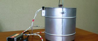
- There are quite a few ways to make a toroid. Copper tubes can be used. But it’s easier to take a regular aluminum corrugation and a metal crossbar for fastening to the protruding end of the wire. If the wire is too flimsy to hold the toroid, you can use a nail, like in the picture below;
- Don't forget about the protective ring. Although if one end of the primary circuit is grounded, it can be abandoned;
- When the design is ready, the transistor is connected according to the circuit, attached to a radiator or cooler, then you need to supply power and the installation is completed.
The first coil can be made flat, as in the picture
Many people use a regular Duracell crown to power the installation.
DIY Tesla transformer, simple circuit
Design and assembly
The Tesla transformer was patented in 1896 and is simple in design. It includes:
- A primary coil with a copper core winding with a cross-section of 6 mm², in an amount sufficient for 5-7 turns.
- A secondary coil made of dielectric material and wire with a diameter of up to 0.5 mm and a length sufficient for 800-1000 turns.
- Hemispheres of the arrester.
- Capacitors.
- A protective ring made of copper core, like on the primary winding of a transformer.
The peculiarity of the device is that its power does not depend on the power of the power source. The physical properties of air are more important. The device can create oscillatory circuits using various methods:
- using a spark gap arrester;
- using a transistor oscillation generator;
- on lamps.
To make a Tesla transformer with your own hands you will need:
- For the primary winding - 3 m of thin copper tube with a diameter of 6 mm or a copper core of the same diameter and length.
- To assemble the secondary winding, you need a PVC pipe with a diameter of 5 cm and a length of about 50 cm and a PVC threaded fitting for it. You also need a copper wire coated with varnish or enamel with a diameter of 0.5 mm and a length of 90 m.
- Metal flange with an internal diameter of 5 cm.
- Various nuts, washers and bolts.
- Arrester.
- Smooth hemisphere for the terminal.
- You can make the capacitor yourself. It will require 6 glass bottles, table salt, rapeseed or vaseline oil, and aluminum foil.
- A power supply capable of delivering 9kV at 30mA will be required.
The Tesla transformer circuit is easy to implement. There are 2 wires coming from the transformer with a spark gap connected. Series-connected capacitors are connected to one of the wires. At the end is the primary winding. The secondary coil with a terminal and a grounded protection ring is located separately.
Description of how to assemble a Tesla coil at home:
- A secondary winding is made by first securing the edge of the wire to the end of the pipe. It should be wound evenly, without allowing the wire to break. There should be no gaps between the turns.
- When finished, wrap the top and bottom of the wrapping with masking tape. After this, coat the winding with varnish or epoxy resin.
- Prepare 2 panels for the bottom and top bases. Any dielectric material, a sheet of plywood or plastic, will do. Place a metal flange in the center of the lower base and secure it with bolts so that there is space between the lower and upper bases.
- Prepare the primary winding by twisting it into a spiral and securing it to the upper base. After drilling 2 holes in it, bring the ends of the tube into them. It should be secured in such a way as to prevent contact of the windings and at the same time maintain a distance of 1 cm between them.
- To make a spark gap you will need to place 2 bolts opposite each other in a wooden frame. The calculation is made that when moving they will play the role of a regulator.
- Capacitors are manufactured as follows. Glass bottles are wrapped in foil and salted water is poured into them. Its composition should be the same for all bottles - 360 g per 1 liter of water. They pierce the covers and insert wires into them. The capacitors are ready.
- All nodes are connected according to the scheme described above. Be sure to ground the secondary winding.
- The total number in the primary winding should be 6.5 turns, in the secondary - 600 turns.
The described sequence of actions gives an idea of how to make a Tesla transformer yourself.
A brilliant seer and a guest from the future
The most famous and most mysterious enthusiast of the idea was the Serbian Nikola Tesla. The free energy generator is just one of the inventions of the brilliant scientist, the owner of almost a thousand patents. He was born in the mid-19th century in what is now Croatia. He, like some other atypical people, has two biographies.
great scientist
It is believed that the Serbian scientist not only laid the foundation for modern electrical engineering, but also made a major contribution to the continuation of the industrial revolution - its so-called second stage. Tesla gained fame in various fields of science. He is responsible for alternating current devices, a synchronous generator, an asynchronous motor and many other inventions. The official data from his biography are widely known:
- Since 1884, Nikola Tesla lived in the USA. In a short time of collaboration with Edison, he was able to improve many of his direct current devices on a dare. Later, the scientists parted ways, and the famous “War of Currents” broke out.
- In 1887, the Serb created the Tesla Electric Company.
- He studied high-frequency magnetic fields. Some of his developments are still used in medicine and electrotherapy. It is significant that the scientist first tested the effect of alternating currents on himself.
- He developed field theory and methods for transmitting electricity using multiphase alternating current. They are now the backbone of the global energy system. For example, light enters homes and businesses.
- Even before Marconi, he described the principles of radio communication. Later he improved the transmission of radio frequencies over long distances.
- Invented devices for detecting submarines and suppressing sound.
- At his instigation, outdoor advertising based on luminous tubes appeared on city streets.
- Made the first electric motor. Conducted successful tests of an electric vehicle. Invented an electric submarine.
- Worked on the study and use of x-rays.
- He predicted the appearance of weapons such as the atomic bomb, and thought through ways to study the nucleus.
- He was the first to build a device that could be controlled remotely.
- He repeatedly voiced ideas that were later used in the development of robotics.
Mysterious wizard
Many of the scientist’s inventions went with him. Successful experiments with the ether have not yet been explained, although the principle of operation of the Tesla generator is known. Free energy from the ether was not his goal in itself. The scientist sought to understand the world. Revolutionaries in this field are always surrounded by secrets. To understand the riddle of the great Serb, it will be interesting to know:
- The future engineer and inventor could become a priest. He received not only a technical, but also a philosophical education.
- In his youth, he was fond of playing cards until he lost completely and had to pay off his debts to his relatives.
- In the USA, after a quarrel with Edison, he was a tramp, an auxiliary worker, hired out as a day laborer, and dug ditches.
- Never married. Didn't get close to anyone. Preferred to work alone.
- Penetrated the secret of ball lightning and knew how to create them artificially.
- He was superstitious and had the gift of foresight. Several times, using this ability, he saved people from possible troubles and even death.
- He had incredible performance. I slept 2 hours a day.
- He began to build a secluded laboratory on the then deserted Long Island. Officially, a tower for a radio station was supposed to appear in this place. Unofficially, it was here that ideas for using atmospheric electricity could be worked out in practice. There was allegedly not enough money to complete the project. The base was subsequently destroyed.
- The tower on Long Island is associated with rumors of the development of death rays, a directed combat emitter and an ultrasonic gun. Later, the Serb's ideas could be used to create a laser.
- During the First World War, Tesla not only raised funds to help Serbia, but also thought about creating an absolute weapon capable of destroying enemy armies at once. It is unknown how far he went along this path.
- Some researchers associate the mystery of the Tunguska meteorite with the scientist. He was really interested shortly before the fall of the celestial body in the remote and most uninhabited territories of Siberia.
- Events similar to the Tunguska events were also observed in the Indian Ocean. The Serb was accused of “shaking” the airwaves here.
https://youtube.com/watch?v=ADgslAI14Dw
What is a Tesla Free Energy Generator?
To understand how the device works, you should familiarize yourself in more detail with the features of its design. a specially prepared iron plate rises as high as possible. Another plate is installed in the ground. A wire is run from the iron plate to one side of the capacitor. The other wire goes from ground to the other end of the capacitor.
All sources of radiant energy emit microscopic particles that carry a positive charge, which, when interacting with a metal plate, transfer a constant electrical charge to it. The capacitor terminal, mounted on the opposite side of the device, is connected to the ground, which in turn can act as a giant reservoir filled with negative electricity. A small current is constantly flowing into the capacitor, and since the particle charge potential is high enough, the capacitor can be energized almost constantly. Elementary in its design, the device actually corresponds to the claim of developing a fuel-free generator using cosmic radiation as an energy source.
What it is?
A fuel-free generator is not the most difficult device to assemble with your own hands. The easiest way to use neodymium magnets in the design
During operation, a conventional engine generates electric current using copper or aluminum coils, but for this it is important to have a constant source of electricity from the outside; the output losses are too large. But if a generator without fuel electricity does not use copper or aluminum as the main materials, much less energy goes into the void
This is facilitated by the presence of a constant magnetic field, which generates an impulse for the operation of the engine.
Important! This design will only work if neodymium magnets are used; they work more efficiently than other analogues and, due to the general interaction, do not require external recharging. As for non-traditional power sources, there are quite a lot of alternative options.
The benefits of an electric motor are easy to grasp: the cost of travel is significantly reduced. The main thing in the design is the engine, which generates a level of direct current with a battery included; it is this that starts the engine, which, in turn, starts the operation of the alternator. As a result, the battery does not discharge.
Traditional sources of fuel-free energy are external factors such as wind or water, but they are not suitable for a generator. Today, magnetic generators are several times superior in performance to conventional solar batteries. However, the scope of application of such a generator is limited by how powerful the current motor is used in the design and other components.
Switching on, checking and adjusting
It is advisable to carry out the first start-up outdoors; you should also remove all household appliances away to prevent their breakdown. Remember safety precautions! To start, perform the following steps:
- They go through the entire chain of wires and check that bare contacts do not touch anywhere, and that all nodes are securely fastened. In the arrester, a small gap is left between the bolts.
- Apply voltage and observe the appearance of the streamer. If it is absent, a fluorescent lamp or incandescent lamp is brought to the secondary winding. It is advisable to secure them to a dielectric; a piece of PVC pipe will do. The appearance of a glow confirms that the Tesla transformer is working.
- If there is no glow, swap the leads of the primary coil.
If it doesn't work out the first time, don't despair. Try changing the number of turns in the secondary winding and the distance between the windings. Tighten the bolts in the arrester.
Transformer
The issue is partially solved by selecting the diameter and quantity of the primary winding of the transformer. The optimal winding diameter is 50 mm, so it is convenient to use a piece of plastic sewer pipe of the appropriate length for winding. It has been experimentally established that the number of turns of the winding should be at least 800; it is better to double this number. The diameter of the wire is not significant for a homemade design, since its power is low. Therefore, the diameter can be in the range from 0.12 to 0.5 mm. A smaller value will create difficulties during winding, and a larger value will increase the dimensions of the device.
Transformer design
The length of the pipe is taken taking into account the number of turns and the diameter of the wire. For example, PEV-2 wires 0.15 mm in diameter with insulation are 0.17 mm, the total length of the winding is 272 mm. Having retreated 50 mm from the edge of the pipe for fastening, drill a hole for fastening the beginning of the winding, and after 272 mm another one for the end. The pipe margin on top is a couple of centimeters. The total length of the pipe section will be 340-350 mm.
To wind the wire, thread its beginning into the bottom hole, leave a margin of 10-20 cm there and secure it with tape. After the winding is completed, its end of the same length is threaded into the upper hole and also secured.
The finished winding must be coated on top with electrical varnish or epoxy resin to prevent shifting of the turns.
For the secondary winding you need a more serious wire with a cross section of at least 10 mm2. This corresponds to a wire with a diameter of 3.6 mm. If it's thicker, that's even better.
Note! Since the system operates at a high frequency, due to the skin effect, the current propagates in the surface layer of the wire, so you can use a thin-walled copper tube instead. Skin effect is another justification for the large diameter of the secondary winding wire
The diameter of the turns of the secondary winding should be twice as large as the primary, that is, 100 mm. The secondary can be wound on a 110 mm section of sewer pipe or on any other simple frame. A pipe or a suitable blank is needed only for the winding process. The rigid winding will not need a frame.
For the secondary winding, the number of turns is 5-6. There are several design options for the secondary winding:
- Solid;
- With a distance between turns of 20-30 mm;
- Cone-shaped with the same distances.
The cone-shaped one is of the greatest interest because it expands the tuning range (has a wider frequency band). The lower first turn is made with a diameter of 100 mm, and the upper one reaches 150-200 mm.
Important! It is necessary to strictly maintain the distance between the turns, and the surface of the wire or tube must be made smooth (at best, polished)
Selection of materials and parts
We will search and select parts for each of the above structural units:
- Power supply requires 12 - 19 V DC voltage. A machine battery, a laptop charger or a step-down transformer with a diode bridge will be suitable to produce direct current.
- Let's find the details for the primary circuit:
— Variable resistor R1 with a nominal value of 50 kOhm. For successful assembly, do not forget to connect the two contacts of this resistor according to the diagram.
— Resistor R2 with a nominal value of 75 Ohms.
— Transistor VT1 D13007 or a Soviet analogue with an NPN structure.
— A radiator for cooling the transistor can be found on powerful transistors in faulty equipment. Size directly affects the quality of cooling.
— Primary winding of the Tesla transformer. The conductor can be a simple copper tube or wire with a diameter of 0.5–1 cm. The winding is made flat, cylindrical or conical (Fig. 2).
- The secondary circuit consists of a coil and, if necessary, a terminal. The winding is made with wire with a diameter of 0.1 to 0.3 mm². The wire can be wound on a dielectric PVC tube. The length of the tube is 25–40 cm, and the diameter is 3–5 cm. It should be wound turn to turn: without intersections or gaps. To prevent the winding from slipping and unwinding, it is recommended to secure the wound sections. The number of turns is from 700 to 1000 (Fig. 3).
After winding, we insulate the secondary coil with paint, varnish or other dielectric. This will prevent the streamer from getting into it.
Terminal – additional capacity of the secondary circuit, connected in series. For small streamers it is not necessary. It is enough to bring the end of the coil up 0.5–5 cm.
After we have collected all the necessary parts for the Tesla coil, we begin to assemble the structure with our own hands.
General operating principles
The sequence of operation of such a BTG is as follows:
The initial power from the supply battery (for example, solar) is accumulated by a high-capacity capacitor.
Upon reaching a given potential difference, the capacitor is discharged and transmits an impulse to the primary winding of the transformer. As an intermediate link, a capacitive cascade of two parallel-connected diodes and a capacitor is used, which smoothes out the inevitable voltage ripples.
The power is sensed by an inductor, which is connected to the primary winding of the transformer. The secondary winding is a series-connected oscillating circuit and another inductor, in parallel with which a diode bridge operates. The purpose of the latter is to limit peak power values, which theoretically can reach infinity.
Part of the primary winding of the transformer is reserved for load, and part is connected to ground. This is necessary to limit the generated power and extend the life of the circuit elements.
To avoid spontaneous pulse discharge, all other elements of the circuit - the primary oscillating circuit, as well as the terminals of the primary and secondary windings of the transformer are grounded.
Thus, the energy consumed by the circuit is constant and sufficient to power the load - the local lighting system, as well as the drives of any small devices or devices. At the same time, due to the pulsed nature of the output voltage, the BTG on a transformer cannot be used to power DC motors.
Important! It should be taken into account that any external energy source - solar battery, magnets, etc. - does not differ in power regularity
Therefore, despite the absence of mechanical transmission systems, some of the energy will be dissipated in the circuits and lost due to the electrical resistance of the wires.
Next, the most available options for the practical production of BTG from 50 Hz transformers are analyzed.
Design and assembly
We carry out the assembly according to the simplest scheme in Figure 4.
We install the power supply separately. The parts can be assembled by hanging installation, the main thing is to avoid short circuits between the contacts.
When connecting a transistor, it is important not to mix up the contacts (Fig. 5).
To do this, we check the diagram. We tightly screw the radiator to the transistor body.
Assemble the circuit on a dielectric substrate: a piece of plywood, a plastic tray, a wooden box, etc. Separate the circuit from the coils with a dielectric plate or board with a miniature hole for the wires.
We secure the primary winding so as to prevent it from falling and touching the secondary winding. In the center of the primary winding we leave space for the secondary coil, taking into account the fact that the optimal distance between them is 1 cm. It is not necessary to use a frame - a reliable fastening is enough.
We install and secure the secondary winding. We make the necessary connections according to the diagram. You can see the operation of the manufactured Tesla transformer in the video below.
What do fuel-free generator manufacturers promise?
On the Internet you can find various sites that offer to buy BTG, and for quite a lot of money (on average - 12 thousand rubles). Moreover, each seller explains the principle of operation of the mechanism in his own way.
Some say that a fuel-free generator operates on some kind of “earth energy”, for others the source is ether, and others talk about static energy, which does not obey the known laws of physics, but is quite real.
IMPORTANT! The theory of the ether was relevant until the beginning of the twentieth century, until in 1910 Einstein refuted it in his scientific article “The Principle of Relativity and Its Consequences in Modern Physics.” In fact, BTG is a beautiful invention, and similar devices do not exist in nature
In fact, BTG is a beautiful invention, and similar devices do not exist in nature.
However, for those who are new to physics, the explanations about the ether and “earth energy” are quite enough to buy an expensive but useless generator.
Is it possible to make a fuel-free generator with your own hands?
If you are still in doubt, try assembling such a generator yourself. There are many different schemes on the Internet for collecting BTG at home. Among them, there were two fairly simple methods: wet (or oil) and dry.
Oil method of collecting BTG
You will need:
- AC transformer – necessary to create constant current signals;
- Charger – ensures uninterrupted operation of the assembled device;
- Battery (or regular battery) – helps accumulate and conserve energy;
- Power amplifier – will increase the current supply;
What is a lithium ion battery - device and types
The transformer must be connected first to the battery and then to the power amplifier. Now a charger is connected to this design, and the portable BTG is ready!
Dry method
You will need:
- Transformer;
- Generator prototype;
- Undamped conductors;
- Dynatron;
- Welding.
Connect the transformer to the generator prototype using undamped conductors. Use welding for this. A dynatron is needed to control the operation of the finished device. Such a generator should work for about 3 years.
The success and effectiveness of these designs largely depends on your luck. You will also need it to find all the necessary elements specified in the instructions. But you probably already guessed that all this is unlikely to work.
Adams generator
In 1967, a patent was received for the production of this generator. The BTG turned out to be working, but the power it produced was so small that it would hardly be possible to provide energy to even a small room with its help.
But scammers don't care. Therefore, on the Internet you can find sites selling the Adams generator. But why spend money on a device that won’t help you save money?
Recommendations for selection
Any such devices (especially magnetic generators) cost quite a lot. Often, consumers want to buy a high-quality model, but at the same time spend a minimal amount of money. Recently, people have started purchasing goods from China. This is due to the fact that the products are cheap and have quite tolerable quality. Generators or structural elements can be purchased abroad, but there are certain risks that should be taken into account:
- You have to pay for the product before receiving it.
- It often happens that products do not correspond to the description on the website.
- Sometimes the package does not reach the recipient, and no one will return the money.
Often such savings turn out to be false. It is possible to purchase a generator directly from the manufacturer. But with this option, you need to know all the intricacies of the device’s design so that an experienced seller cannot “sell in” a generator that does not meet the requirements, so before purchasing you should:
- Thoroughly study the market for such devices. This will allow you to discover leaders among manufacturers.
- Correctly calculate the power. This way you can save money without overpaying for unnecessary features.
How to make a fuel-free generator with your own hands
There are two most common ways to make BTG with your own hands:
- wet;
- dry.
The wet method will require a battery, while the dry method will require batteries.
Wet method
Required components:
- charger of the required caliber;
- battery;
- amplifier;
- transformer for alternating current.
The battery serves as an energy storage device and also stores it. A transformer is needed to generate constant electrical current signals. The amplifier, in turn, increases the level of current supply, since the initial power of the battery is about 12 or 24 V. A charger will be needed for constant and uninterrupted operation of the device.
First you need to connect the transformer to a permanent network or to a battery, and then to a power amplifier. After which you will need to connect the sensor for expansion to the charger circuit. Then you need to connect the sensor back to the battery.
Dry method
The operating principle of a dry device is to use a capacitor.
To create such a device you need:
- transformer;
- generator prototype.
First of all, it is necessary to connect the transformer and the prototype using special conductors (non-damped). It is recommended to do this by welding to create the strongest possible connection. To check the work done, you need to use a dynatron.
BTG scheme:
A working diagram of how to make a BTG with your own hands:
Also today, new BTG schemes are being released, which provide for connection to several batteries and other generators.
Practical circuits of free energy generators
Obtaining minimum capacity occurs in several ways:
- through magnets;
- using the heat of water;
- from ferrimagnetic alloys;
- from atmospheric condensate.
However, in order to obtain electricity in large quantities, you need to learn how to manage this energy. Thanks to the practical design of free energy generators, light should reach every person, regardless of local location. This is confirmed by historical facts. Such an experiment requires enormous radiation power, which could not have been available in those days.
And even today existing stations are not capable of providing such a charge. To create a free energy generator circuit, certain tools and elements are required. So, to get the required amount of charged power, you would need a coil, which is what Tesla was using at the time. Electricity is received in the quantity that is needed.
Modern look and new developments
Despite widespread interest in creating a free energy generator, they are still unable to displace the classical method of generating electricity from the market. Developers of the past, who put forward bold theories about significantly reducing the cost of electricity, lacked the technical perfection of the equipment or the parameters of the elements could not provide the desired effect. And thanks to scientific and technological progress, humanity is receiving more and more inventions that make the embodiment of a free energy generator already tangible. It should be noted that today free energy generators powered by the sun and wind have already been obtained and are actively being used.
But, at the same time, on the Internet you can find offers to purchase such devices, although most of them are dummies created with the aim of deceiving an ignorant person. And a small percentage of actually operating free energy generators, whether on resonant transformers, coils or permanent magnets, can only cope with powering low-power consumers; they cannot provide electricity, for example, to a private house or lighting in a yard. Free energy generators are a promising direction, but their practical implementation has not yet been implemented.
alternative energy
Supporters of traditional physics and energy deny the possibility of creating a workable generator, using existing concepts, laws and definitions. A lot of evidence is given that such devices cannot exist in practice, since they contradict the law of conservation of energy.
Proponents of the “conspiracy theory” are convinced that calculations of the generator exist, as well as its working prototypes, but they are not presented to science and the general public, since they are not profitable for modern energy companies and can cause an economic crisis.
Enthusiasts have repeatedly attempted to create a generator; they have built many prototypes, but for some reason reports on the work regularly disappear or disappear. It has been noted that network resources dedicated to alternative energy are periodically closed.
This may indicate that the design is actually functional, and it is possible to create a generator with your own hands even at home.
Galvanic cell
The next method is simple chemistry. This is the most realistic and understandable way to generate electricity from the ground at home. For this you need copper and zinc electrodes. Their role can be plates, pins, nails. If copper is common, problems with zinc may arise, so it is easier to find galvanized iron.
You need to drive your electrodes into the ground at the same distance from each other. Let's say 1 meter deep and 0.5 meters between the electrodes. In this case, copper will be the cathode and zinc will be the anode. The voltage of such an element can be of the order of 1-1.1 Volts. This means that in order to get 12 volt electricity from the ground, you need to drive 12 such electrodes and connect them in series.
The decisive factor in such a battery is the area of the electrodes; the current strength depends on this, as well as on what is located between them. In order for the battery to produce current, the ground must be moist, for this it can be watered, sometimes the zinc electrode is filled with a solution of salt or alkali. To increase the current output, you can pack more electrodes and connect them in parallel. All modern batteries and accumulators are designed this way.
In the diagram below you see another interesting implementation of such a battery made of copper pipes and galvanized rods.
However, over time, the electrodes will deteriorate and the battery will gradually stop working.
Security measures
Once you have collected the CT, you need to take some precautions before launching. First, you need to check the wiring in the room where you plan to connect the transformer
Secondly, check the insulation of the windings.
It is also worth remembering the simplest precautions. The voltage of the secondary winding is on average 700A, 15A is already fatal for a person
Additionally, it is worth putting away all electrical appliances; if they get into the coil’s operating area, they are likely to burn out.
CT is a revolutionary discovery of its time, underestimated today. Today the Tesla transformer is used only for the entertainment of home electricians and in light shows. You can make a coil yourself using available materials. You will need a PVC pipe, several hundred meters of copper wire, a couple of meters of copper pipes, a transistor and a couple of resistors.
Components and operating principle
All Tesla transformers, due to a similar operating principle, consist of identical blocks:
- Power supply.
- Primary circuit.
- Secondary circuit.
The power supply provides the primary circuit with voltage of the required magnitude and type. The primary circuit creates high-frequency oscillations that generate resonant oscillations in the secondary circuit. As a result, a current of high voltage and frequency is formed on the secondary winding, which tends to create an electrical circuit through the air - a streamer is formed.
The choice of primary circuit determines the type of Tesla coil, power source and size of the streamer. Let's focus on the semiconductor type. It features a simple circuit with accessible parts and a low supply voltage.
Theoretical basis
The influence of the theory of relativity (TR)
The term “free energy of the ether” in scientific circles refers to special field formations, the maintenance of which does not require specific physical carriers (wires, in particular). The emergence of this concept is associated with the widespread dissemination of the theory of relativity, the foundations of which were laid by A. Einstein at the beginning of the last century.
Thanks to this, N. Tesla’s idea of free energy received its further development, consisting in the emergence of completely new approaches to the perception of time and space. The introduction of such specific concepts as its curvature and the relativity of time left a certain imprint on the formation of the doctrine of free energy spreading outside of physical media.
However, neither the general nor the special parts of the technical theory were able to explain the absolutely incomprehensible to humans phenomena of mass change and almost instantaneous transmission of e/m fields over vast distances. At the same time, despite the obstacles posed by representatives of “traditional” science, the number of supporters of the ether theory only increased every year.
Other justifications
There are several other theories that partially confirm the correctness of the above approach to the idea of free energy. These are such discoveries of recent years as:
- Phenomena associated with so-called “dark matter”;
- The notorious theories of the ether;
- The doctrine of torsion field (authors - G. Shipov and A. Akimov).
Note! These non-traditional approaches to representing field structures should not be confused with the provisions of quantum information theory, which uses the concept of “system state” as the main one. Despite all the incomprehensibility of the principles of the formation and distribution of free (unbound) energy, on its basis it was possible to develop a number of devices, the principle of operation of which is quite explainable at a practical level
Let us consider the features of the creation and operation of these energy generators in more detail. Several examples and videos will help with this, showing how to assemble and put them into operation.
Despite all the incomprehensibility of the principles of the formation and distribution of free (unbound) energy, on its basis it was possible to develop a number of devices, the principle of operation of which is quite explainable at a practical level. Let us consider the features of the creation and operation of these energy generators in more detail. This will be helped by several examples and videos showing how to assemble and put them into operation.
Parameters and characteristics
The Tesla electric generator uses the principle of a transformer with a missing core. The design consists of a primary coil with turns of large diameter wires, and a secondary coil with turns of thinner wires. A device without a magnet does not have a traditional ferromagnetic core, which distinguishes it from a conventional transformer. Thanks to this design, the level of mutual inductance of the coils is significantly reduced. A large number of turns on the secondary coil contributes to the formation of high voltage with a minimum of energy costs.
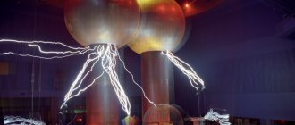
This theory has found clear practical confirmation. Home craftsmen, using a 40 W free energy generator, receive voltages of up to 500 kilovolts. This leads to the formation of long, beautiful discharges reaching two or three meters in size. Once in the atmosphere, the high-voltage discharge becomes like a kind of corona. It is impossible to achieve such productive work and visual results with a conventional transformer.
In addition to air effects, long mobile charges are formed upon contact with grounded objects. It should be noted that all discharges have certain frequencies, and other frequencies are multiples of the original value.
Each such high-voltage charge consists of a certain set of frequencies capable of breaking up gas molecules, regardless of the stability of any of them. The splitting process is accompanied by the appearance of a dark blue color with a greenish tint.
RESULTS
ROOM 1. Ð 1928 1928 ROOM ¸Ð»Ð¸ беÑÑопливнÑм генеÑаÑоÑом Ð ¥ÐµÐ½Ð´ÐµÑÑоÑа. RESULTS ½Ð¾Ð¼ ÑаÑположении пÑибоÑÐ ° ÑоглаÑно магниÑÐ½Ð¾Ð¼Ñ Ð¿Ð¾Ð»Ñ Ðемли. RESULTS 3 00 R. ROOM бÑеÑение.
1961 1961 1961 RESPONSIBILITY RESULTS µ, µ ¿Ð¾ ÑакÑÑ ÑолÑко запÑÑало ÑаÑÑледование. RESULTS ¸Ð¹Ð½Ð¾Ðµ пÑоизводÑÑво Ñвоей модели .
УÑÑÑойÑÑво наÑолÑко пÑоÑÑо в иÑполнении, OUR RESEARCH елаÑÑий. RESEARCH ROOM RESULTS ÑнеÑгиÑÂ.” RESULTS демонÑÑÑиÑÑÐµÑ Ð¿ÑоÑеÑÑ ÑбоÑки ÑÑÑÑойÑÑва. 2.5 â 3 × ASSURANCE ASSURANCE
How to make a generator
To assemble a Tesla generator, you need very little. On the Internet you can find information on assembling a Tesla generator transformer with your own hands and diagrams for starting the structure. Based on the available information, recommendations are given below on how to independently assemble the structure and a brief setup procedure.
The transformer must satisfy conflicting requirements:
- High-frequency free energy requires a reduction in size (similar to the difference in size of meter and decimeter range television antennas);
- As the dimensions decrease, the efficiency of the structure decreases.
Power supply circuit
For the initial start-up, a circuit is required that supplies a pulse of energy to the Tesla generator transformer. Next, the generator switches to self-oscillating mode and does not constantly need external power.
In developer slang, the power supply device is called a “kacher”. Those familiar with electronics know that the correct name for the device is a blocking oscillator (shock oscillator). Such a circuit solution generates a single powerful electrical impulse.
Many variants of blocking generators have been developed, which are divided into three groups:
Read also: “A finger on the throat
- On vacuum tubes;
- On bipolar transistors;
- On field-effect transistors with an insulated gate.
A tube electromagnetic generator using powerful generator tubes operates with high output parameters, but its design is hampered by the availability of components. In addition, not two, but three winding transformers are required, so tube blocking oscillators are now rare.
Tube blocking generator
The most widely used devices are those based on bipolar transistors. Their circuitry is well developed, setup and adjustment are simple. We use domestically produced transistors of the 800 series (KT805, KT808, KT819), which have good technical parameters, are widespread and do not cause financial difficulties.
Blocking oscillator based on a bipolar transistor
The proliferation of powerful and reliable field-effect transistors has made it possible to design blocking oscillators with increased efficiency due to the fact that MOSFET or IGBT transistors have better parameters for voltage drop across transitions. In addition to increasing efficiency, the problem of cooling transistors becomes less problematic. Proven circuits use IRF740 or IRF840 transistors, which are also inexpensive and reliable.
Field effect transistor circuit
Before assembling the generator into a finished structure, double-check the workmanship of all components. Assemble the structure and supply power to it. The transition to self-oscillating mode is accompanied by the presence of voltage on the windings of the transformer (at the output of the secondary). If there is no voltage, then it is necessary to adjust the frequency of the blocking generator in resonance with the frequency of the transformer.
Important! When working with a Tesla generator, extreme caution must be exercised, since when starting, high voltage is induced in the primary winding, which can lead to an accident.
Generator circuits for 555
Then I decided to fundamentally change the circuit and make independent duration on the capacitor, diode and resistor. Many may consider this scheme absurd and stupid, but it works. The principle is this: the signal goes to the driver until the capacitor is charged (I think no one will argue with this)
NE555 generates a signal, it goes through a resistor and a capacitor, and if the resistance of the resistor is 0 Ohm, then it goes only through the capacitor and the duration is maximum (as long as the capacitance is enough) regardless of the duty cycle of the generator. The resistor limits the charging time, i.e.
The greater the resistance, the shorter the pulse will take. The driver receives a signal of shorter duration, but of the same frequency. The capacitor discharges quickly through a resistor (which goes to ground 1k) and a diode.
Advantages and disadvantages
Pros : frequency-independent duty cycle adjustment, SSTC will never go into CW mode if the breaker burns out.
Cons : the duty cycle cannot be increased “infinitely”, as for example on the UC3843 , it is limited by the capacitance of the capacitor and the duty cycle of the generator itself (it cannot be greater than the duty cycle of the generator). The current flows smoothly through the capacitor.
I don’t know how the driver reacts to the latter (smooth charging). On the one hand, the driver can also smoothly open the transistors and they will heat up more. On the other hand, UCC27425 is a digital chip. For it there is only a log. 0 and log. 1. This means that as long as the voltage is above the threshold, the UCC works; as soon as it drops below the minimum, it does not work. In this case, everything works as normal, and the transistors open completely.
Main types of coils
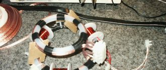
Homemade tesla coil.
Tesla himself manufactured only one type of Transformer - a spark gap (SGTC).
Since then, the element base has greatly improved, and many different types of coils have appeared; by analogy, they continue to be called Tesla coils.
Coil types are usually named from English abbreviations. If the name must be said in Russian, English abbreviations are simply spoken in Russian letters without translation. We will consider the most common types of Tesla coils below.
SGTC (SGTC, Spark Gap Tesla Coil)
Tesla transformer on a spark gap. The very first and “classical” design (it was used by Tesla himself). It uses a spark gap as a key element. In low-power designs, the arrester is simply two pieces of wire located at some distance, while in high-power designs, complex rotating arresters are used. Transformers of this type are ideal if you only need a long streamer length.
VTTC (VTTC, Vacuum Tube Tesla Coil
Tesla transformer on a lamp. A powerful radio tube is used as a key element. Such transformers can operate in continuous mode and produce thick, “fat” streamers. This type is most often used for high-frequency adzes, which, due to the characteristic appearance of their streamers, are called “torch”.
SSTC (SSTC, Solid State Tesla Coil)
Tesla transformer, which uses semiconductors as a key element. Usually these are MOSFET or IGBT transistors. This type of transformers can operate in continuous mode. The appearance of the streamers created by this coil can be very different. This type of Tesla is the easiest to control (play music, for example).
Solid State Tesla Coil type.
DRSSTC (DRSSTC, DRka, Dual Resonant Solid State Tesla Coil)
A transformer with two resonant circuits, in which semiconductors are used as switches; in the vast majority of cases, these are IGBT transistors. DRSSTTS is the most difficult type of Tesla transformer to manufacture and configure. The characteristic length of the streamers of this type of transformer is slightly shorter than that of the SGTC, and the controllability is slightly worse than that of the SSTC.
To control the appearance of streamers, they came up with a so-called interrupter. Initially, this device was used to stop the coil in order to allow the capacitor to charge and the discharge terminal to cool, and, due to this, to increase the length of the streamers. But recently, additional functions have begun to be built into interrupters, for example, Tesla coils have been taught to play music.
Tesla Coil Configurations
The Tesla transformer has many modifications, depending on this it is used in different areas of life:
- A coil with a rotary mechanism with sparks rotating in different positions. Here, the role of the engine is played by an electric unit with a rotating disk that conducts electrodes.
- Lamp coil with conventional lamps to generate high voltage current. They are capable of conducting voltages up to 600 Volts.
- Semiconductor oscillator with high-frequency master oscillator (more modern design).
- High frequency transformer that outputs current through musical waves. The discharge changes depending on the musical rhythm.
It is enough to change the discharge key to change its type and thereby achieve different discharge forms.
The main difference between them all is their fairly quiet operation, since the spark itself makes little noise.