Expected installation difficulties
The fashion for integrating LED lamps into cars came quickly, and significant pitfalls were immediately discovered when converting them. Regarding the turns of cars of the VAZ family (in particular the VAZ-2110), they manifest themselves in the fact that the frequency of blinking of the turn signal headlights increases.
The reasons for this phenomenon are as follows: LEDs operate at higher resistance values compared to conventional lamps. Therefore, when turned on in this way, they heat up more intensely. As a result, the plate simply heats up, as a result of which the electrical circuit opens.
When the light bulb burns out, the resistance drops sharply, causing the warning light to blink faster. You can replace a regular lamp with an LED, but this does not fundamentally change anything, so you will have to modify the turn relay for LEDs with your own hands.
Solution options
The solution to the problem is described in great detail and high quality in the video, and below we will look at all the options in more detail:
- In parallel with the LEDs, you can include a ballast resistor in the relay circuit (the choice depends on the make of the car, for a VAZ-2110, for example, it is 2.2 kOhm);
- Instead of a resistor, simply add a regular lamp in parallel;
- In the circuit, replace the capacitor with a more capacitive one;
- In parallel to the existing one, you can solder another capacitor with the same capacity.
Each option has its pros and cons. For example, if there is a ballast resistor, the electrical circuit of the turn signal relay will simply increase its power consumption, which will affect the battery life. The resistors will heat up and this will lead to a decrease in the light output of conventional lamps.
Parallel connection of another lamp is associated with difficulties in its safe installation in the same housing. By adding an additional capacitor to the circuit, you will have to come to terms with the fact that the blinking frequency of the direction indicator will significantly decrease (however, in the current rules there are no restrictions on the blinking frequency of LEDs).
Please rate the article. We tried our best:)
Did you like the article? Tell us about her! You will help us a lot :)
How to make dynamic turn signals (stacked) with your own hands from a KIT DIY kit from AliExpress
This designer consists of a printed circuit board measuring 20x55mm and, accordingly, a set of necessary radio components. The installation location of all components and their ratings are indicated on the board, so there are no particular difficulties with installation.
The entire manufacturing process and operation of the circuit can be seen in the video:
List of tools and materials - a set of running lights on a CD4017 or K561IE8 chip (link to the set); -screwdriver; - scissors; - soldering iron; -cambric; - rechargeable battery from a cell phone; -12V power supply; - connecting wires; - foil PCB for printed circuit board; - K561TM2 microcircuits; -resistors; - transistors KT815 (or analogues); -LEDs.
Step one.
PCB wiring kit from AliExpress.
All that is needed is to solder the components of the kit onto the board. Due to the miniature size of SMD radioelements, I used a “third hand” with a magnifying glass. First, I soldered resistors, capacitors and other components of the circuit except microcircuits. At the end we solder the microcircuits and LEDs.
Scheme after modification..
To check the operation, I connected pieces of LED strip with three LEDs to each of the eight channels.
I replaced the 50 kOhm trimming resistor with a 470 kOhm one to expand the limits of pulse frequency adjustment. I found an old turn signal lamp in the garage and covered the LED strip with it. The lighting effect turned out to be quite good.
This is how the weekend design turned out. It was interesting to test out the new scheme, so everything was done quickly. In the future it will be possible to make a new general printed circuit board. A beginner can make such running lights on LEDs on his own without spending a lot of time and money. And where to use them is up to you to decide.
Source
Reworking the relay circuit
The number of LEDs installed in series can be determined experimentally, but in practice 5 pieces are enough: such a load is quite enough to trigger the circuit. At the same time, the circuit on the board opens, which allows it to work with both conventional and LED lamps. However, in this case, the device will not be able to signal that the turn signal bulb has burned out.
The refinement algorithm is considered using the example of a relay that operates using a U643B controller manufactured by the Chinese company Atmel. Such controllers are often used in electronic equipment circuits of modern passenger cars.
One of the functions of such a controller is to warn of a malfunction of the turn signal bulbs. The criterion for malfunction is a critical decrease in the current in the circuit, as a result of which the blinking frequency increases sharply.
Electronic turn signal relay circuit for LEDs
The operating value of the LED current is set at the output of the “Lamp failure detection” controller circuit. The nuance is that the efficiency of LED lamps is much greater than that of conventional lamps. The inconvenience is that the current consumption is reduced, and increased flickering of the LEDs is perceived by the controller as a malfunction of the turn relay.
In order to get rid of this drawback, you simply need to replace resistor R3 of the circuit with a more powerful one. This will lead to an increase in the total load, and a corresponding increase in the current strength - to values at which the turn signals will no longer blink.
An alternative solution for some car enthusiasts is to cut out the section of the circuit in the circuit that is responsible for measuring the current. However, this action also reveals a serious problem.
Since the U643B controller works with its initial parameters already set by the manufacturer, with such “tuning” of the turn signal, you can accidentally change the so-called Device Code - the controller identification code by external devices. It is impossible to reflash it. In addition, by cutting out one of the contacts in the turn signal relay circuit, you can get frequent blinking of the turn signals, which does not always satisfy the car user.
Reverse restoration will most likely not yield anything, since the relay controller has already “remembered” its new parameters and changed the Device Code.
The difficulty in adjusting the parameters of resistor R3 lies in the fact that the part works with initially small resistance values, so precise instruments will be required for adjustment, but from a technical point of view, this approach is more correct.
One example of using LEDs
One of the most common uses of these elements in cars is as a turn signal. Now let's look at how to make LED turn signals from regular ones.
The procedure is as follows:
- The most suitable connection scheme is selected
- The required LED is selected
- Next, all other radio components of the electrical circuit are calculated
- Based on the calculations performed, protective resistors and other components are selected
- Then a list of necessary radio components is compiled. With this list, you need to visit the nearest store of this profile and buy all the necessary equipment there.
- All necessary documentation is being developed (including a drawing of the printed circuit board and its installation drawing)
- Then you need to make a printed circuit board to mount radio components on it. To do this, a pre-designed pattern is applied to the fiberglass board using varnish. All necessary holes for mounting radio components are drilled. She is immersed in ferric chloride. After the design on the board is etched, it is removed. Wash with plain water. Then the protective layer is removed using a solvent. The next step is rinsing again with running water. And only after that it dries. Upon completion of all completed procedures, we receive a ready-made board for further work. Since there are only 4 turn signals, 4 boards must also be made.
- At the next stage, based on the diagram and the developed board drawing, all elements of the circuit are installed. Upon completion of assembly, all contacts must be opened with tsaponlak (it will provide the necessary insulation and protection of the circuit in case of moisture getting here)
Dismantling old turn signals must be done carefully so as not to damage the paintwork.
- Then you need to dismantle the old turn signals and carefully disassemble them. And in such a way as not to damage it.
- The old lighting element (lamp) is completely turned off and removed.
- The joints where everything was previously filled with glue must be cleaned using a needle file and sandpaper. Then this joint is degreased with alcohol. Then all this is washed with water and should dry.
- New LED turn signals are installed in place of the old lighting element. If necessary, minor design changes can be made to simplify the installation process.
- Then reassemble in reverse order. It is necessary to apply glue to the joint and glue the disassembled turn signal. Then you need to wait until the glue hardens. In the future, this turn signal is installed in the old place and the old wires are connected to it.
- At the next stage, it is necessary to make changes to the vehicle's power supply system. To do this, the old wires are broken and an additional stabilized power source is wedged into it (you can purchase it separately or make it yourself). Moreover, its output is set to an LED. The input is supplied with voltage from the contact group of the intermediate relay. It is most convenient to place this element in the dashboard of a car. At the final stage, you need to check the polarity of the connection visually. The anode must be connected only to the positive pole of the power source. In turn, the cathode is to negative. If connected differently, this semiconductor element will not work and may even fail.
- Then it is necessary to inspect the assembled circuit and compare it with the initial version for compliance.
- Next, power is supplied and the functionality of the circuit is checked. If everything is fine, then the installation is complete. Otherwise, it is necessary to find the cause of the malfunction and eliminate it.
Video: homemade turn signals
Limitations and procedure for modifying the turn relay
Installation of LEDs is possible only if the relays are digital. For cars of the VAZ or GAZ family, these are devices marked with the designation 494.3747 (for comparison: the designation for analog ones is 231.3747). When there is no marking, the relay class is quite simply determined by its dimensions, which are noticeably larger for the analog version. If the car only operates analog, you will have to purchase a digital one.
Appearance of digital and analog turn relays
The direction indicator is modified in the following sequence:
- The case is opened;
- The location of the chip responsible for the operation of the turn signals is determined: it is usually located to the right of the external board.
- The capacitor is replaced, which determines the frequency of the turn signal lamp blinking generator. The subtlety is that the capacitor capacity should be within 4.7 µF at 50 V operating voltage. Alternatively, you can install another capacitor; in most cases, the space inside the relay case allows this operation.
- Output parameters are monitored using measuring instruments. If the LEDs are functioning properly, the housing is installed in its original place.
As additional items you should purchase:
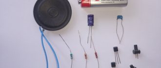
- P-channel transistor;
- A resistor from the above resistance range (if it will be soldered into the circuit and not a capacitor);
- LEDs (preferably red or orange).
Soldering of such a modernized version of the relay can be done using the usual hinged method, on top of the main circuit.
Please rate the article. We tried our best:)
Did you like the article? Tell us about her! You will help us a lot :)
Features of installation and configuration of running direction indicators
You can install dynamic turn signals instead of conventional LEDs. To do this, the repeaters are removed from the mirrors, the board with LEDs and current-limiting resistors is dismantled. On the repeater you need to tear the glass away from the body. Then you should carefully cut out the reflector and remove it.
In place of the remote reflector, an SMD 5730 board is installed, on which yellow LEDs are located. Since the repeater has a curved shape, the board will have to be delaminated and bent a little. You need to cut off the part with the connector from the old board and solder it to connect the controller. Then all components are returned to their place.
