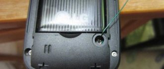
The time has come to install the TV cable. I plan to have a lot of TVs. The city is 40 km away. The broadcaster is even further away. The task is to provide televisions with stable reception of the DVB-T2 signal. I will use signal dividers, which will further weaken the signal received by the antenna. There is a need to use a DVB-T2 antenna amplifier . Since the frequencies of both DVB-T2 packages are in the UHF range, I looked at a directional, passive UHF antenna with a gain of 14 dB.
A large distance to the translator and dividing the signal into several TVs will greatly weaken the signal, so you can’t do without a UHF antenna amplifier, also known as a DVB-T2 amplifier. I decided to make an antenna amplifier for DVB-T2 with my own hands and see what comes of it.
Since standard signal dividers, including those that I purchased, do not pass electric current, powering the amplifier via a cable will not work (or the power must be routed via cable to the divider).
How to make an antenna amplifier with your own hands
Not everyone can independently assemble even the simplest amplifier from radio components for an antenna with their own hands. However, such a device, such as an antenna amplifier for a TV in the country, can be made from improvised materials, for example, from beer cans. It will take very little time to make such an amplifier, but the results are quite good. Using this design allows you to achieve a higher quality picture, minimize noise and detect a larger number of channels.
Before making an amplifier, you need to stock up on two beer cans, a power cable, a plug, and screws. Additionally, you will need a screwdriver, electrical tape and a flat wooden stick.
A homemade antenna amplifier is assembled in the following order:
- Tin cans are screwed to a wooden stick using electrical tape so that a distance of 7-8 cm is maintained between them. If the original rings on the cans are still intact, then they are best used to secure the cable.
- If there are no rings, you should screw self-tapping screws into each can and attach the stripped ends of the cable to them. The wooden stick and cable are also connected with electrical tape, which makes the structure more stable.
- To protect from external influences, both cans can be covered with a plastic bottle, the bottom and neck of which have been previously cut off. A hole is cut in the center of the bottle for the cable.
- The finished structure needs to be connected and configured. A homemade TV antenna amplifier can be improved by adding additional sections to it. Setting up equipment for a TV with your own hands is done by changing the distance between the banks. If the diameter of the can increases, then, accordingly, the signal bandwidth will increase.
Do-it-yourself amplifying device: advantages and disadvantages
Important! It is much easier to buy digital television signal amplifiers online from Chinese manufacturers. Such a device is cheap, and its delivery will be free.
Only such things can encourage you to start making an amplifier yourself - this is the desire to make something of better quality, as well as improve your amateur radio skills. You won't be able to achieve big savings with this option.
Important! If a radio amateur plans to receive a digital signal, then in this case the receiver must be equipped with a “DVB-T2” digital tuner. Otherwise, you will have to purchase an additional receiver for your TV, with which you will be able to watch TV channels in the desired frequency range.
DIY antenna amplifier diagram and description
The antenna amplifier diagram below shows how it should actually be connected to the TV. The TV cable itself passes through the amplifier board, and only then the signal enters the TV.
When making an antenna amplifier with your own hands, you will not need any special materials - mainly, you will need to purchase radio-electronic components, the location of which is shown in the diagram. T1 transistor 2sc3358 - one of the main parts of the circuit of the future device C1 - 10mF / 35v C2, C9 - 1nF C3, C4 - 10 nF C5, C6, C7, C8 - 10 pF - capacitors for surface mounting Resistors R1 - 470 Ohm R2 - 2.2 kOhm, R3 - 1 kOhm, R1 - 5 kOhm Elements L1, L2 - 2 turns 0.5 mm, 3 mm. L3, L4 - 10uH or 10 turns, 0.2 mm on ferrite. 12 volt power supply. On request – with adjustable voltage supply.
Amplifier PCB:
Once again, pay attention to the power supply - 12 volts, which means the need to use capacitors when connecting the assembled device to the power supply. Also, a do-it-yourself TV antenna amplifier can be powered using the antenna cable itself (coaxial cable) if the required voltage is available
After assembly, the board looks like this:
Adjustment of the manufactured amplifier is carried out by moving resistor R1 to the middle position, and then adjusting it after it has been possible to obtain a normal image on the TV screen. After the antenna with amplifier has been assembled and tested with your own hands, you can and should place it in a small metal box, which, in addition, will shield the device from extraneous radiation.
The given method is not the only one possible. With absolutely the same basic diagram, it is permissible to change the elements used in it - this will largely depend on the strength of the signal coming to the television antenna. In turn, the signal is attenuated when passing through the antenna cable - the longer the cable, the weaker the output signal will be. Based on this, when creating an antenna amplifier with your own hands, you need to take into account the signal strength and decide how much gain you need. For example, with a signal level of 10 dB, the best device is one that can increase its strength by 2-3 times.
Power amplifier circuit:
There are also cases where one station transmits a much stronger signal than another, and too powerful an amplifier causes them to overlap each other. This can help by reducing the supplied voltage, for which you should use a power supply with the ability to regulate power. In addition, you can immediately assemble a fairly powerful device, and only then adjust it to your needs, reducing or increasing the voltage supplied to it.
Amplifier for FM receiver
A simple do-it-yourself HF amplifier for the FM range
To receive remote FM stations, we can recommend a simple RF amplifier circuit using a single transistor.
The common emitter UHF circuit is based on a 2SC2570 transistor.
To obtain a good result, the circuit must be soldered on a high-quality fiberglass printed circuit board. The input/output trimmers (VC1 and VC2) need to be adjusted to the maximum signal.
The input coil L1 consists of four turns, wound with a pitch of 5 mm on a mandrel. with a tap from 1 turn. Coil L2 has three turns, wound with a pitch of 5 mm on a mandrel. The coils are wound with copper wire coated with enamel with a diameter of 0.91 mm.
The pinout of the 2SC2570 transistor is shown in the figure above.
This active FM amplifier is powered by 12V DC. Can be used to boost the signal in a car.
How to choose a signal amplifier for your TV
The modern market presents many different models, for this reason, many people find it difficult to decide which device suits them best. To make the right choice, you should consider several important parameters:
- Gain. It should be calculated based on the approximate distance between the TV and the signal source (tower). It should not exceed 150 km. At a distance of no more than 10 km, there is no need to amplify the signal; you just need to choose a suitable antenna. If the distance between your home and the source is more than 10 km, you should not purchase a device with a coefficient higher than necessary - this will lead to the opposite effect and instead of a high-quality image you will see new interference.
- Antenna type. For example, swa models are suitable for array receivers, which operate in the frequency range from 49 to 790 MHz. Some of the most popular modern Locus models are perfectly compatible with LSA amplifiers.
- Frequency range. A good solution for a conventional outdoor receiver (which receives waves of any frequency) would be to install a broadband model, but a better result is shown by a device that operates only in a certain range.
- Noise figure. The lower this parameter, the better the image on the TV screen will be.
Recommendations for selection
So, how to strengthen the digital television signal? First you need to choose a good amplifier that will work in a particular case.
To begin with, find out in what range the broadcast is made in your region: it can be meter and decimeter. In the first case, the maximum frequency is 300 MHz, and in the second – 3 Hz.
Amplifiers are single-range, i.e. work only in one mode, and are universal with a switch. This is the main indicator that you should pay attention to.
However, it is also recommended to study the following:
- Reception range. The minimum range is 30 km, but 150 is better! The indicator indicates the distance between your receiver and the repeater point. It makes no sense to put everything below 30 km, because... there will be almost no effect. Anything more is wasteful, because... Such amplifiers are expensive.
- Reception gain factor. How to improve the signal? Of course, you need to look at how much the amplifier can increase reception. The rule here is: “The further away the repeater, the higher the coefficient.” For a distance of 50 km, a gain of 27 dB is sufficient, i.e. ratio: 1 dB at 1.85 km.
- Nutrition. Some models are powered by a power supply, others by a receiver. According to customer reviews, the first models work better. On the other hand, the latter are much more convenient, because You just need a long USB cable.
- Frame. Depends on the installation location. Models with a plastic body are suitable for indoor use, and metal ones for outdoor use.
TOP 4 good amplifier
1 Model SWA9001/999/9701 (L) broadband. A good broadband amplifier without adjustment. Suitable for both home installation and mast installation. It is recommended to install an additional metal screen. Capable of picking up a signal up to 100 km.
2 Televes. A good 5-output Italian amplifier with a gain of 15 dB. The signal increase is not very large, but excellent noise reduction is provided. Powered by the included power supply.
3 Gecen A05-02. Satellite and digital amplifier operating in both the meter and decimeter range. It is powered via a coaxial cable, which is not very good, but there is no need to purchase an additional power supply or USB.
4 RTM LNA02. An excellent model with a gain of 20 dB. It has excellent noise reduction and is powered by the receiver. Well suited for broadcast-restricted areas.
Amplifier selection
The antenna amplifier is connected as close as possible to the TV antenna. Placing it near the receiver will increase the noise along with the transmitted signal, and the image will be worse. The power supply can be placed near the amplifier, or separately.
Home antenna made together with an amplifier
The parameters that determine the correct choice of amplifier are as follows:
- distance from the television center;
- required frequency range;
- the type of antenna for which the signal is amplified.
The maximum distance to the signal transmission source should not exceed 150 km. At a distance of less than 10 km, an amplifier is usually not installed, since the signal level is quite high. To obtain a normal signal, it is advisable to choose a good antenna. How to make a TV antenna with your own hands from wire.
The gain should not be too high, otherwise significant noise may appear from self-excitation. Many models produced have different characteristics. Here it is worth contacting a specialist who knows how to improve reception and will help you choose the necessary device. Installing a broadband amplifier on the antenna makes it possible to cover the entire television broadcast range.
In Russia, antennas with amplifiers made in Poland (ANPREL) are common. Their own gain is small, and the parameters are mainly determined by the additional amplifier. It has the following disadvantages: self-excitation, high level of generated noise, overload from powerful signals in the MV range, damage from lightning discharges, passive output losses.
In most TV amplifiers, they operate according to a standard two-stage circuit based on high-frequency bipolar transistors with a common emitter.
Amplifiers on two stages: SWA-36 (a) and SWA-49 (b)
The amplifier stage captures the wideband band. The input signal is fed to the base of the transistor (T1) through a capacitor (C1). The necessary linear characteristic in it is created by applying a bias voltage through a resistor (R1). But at the same time the gain decreases. The next stage is created according to a similar circuit with stabilization of the transistor (T2) in the emitter circuit by feedback through a resistor (R4).
It is not recommended to significantly increase the Kp of the antenna amplifier, since it creates its own noise, which increases along with the input signal. It is not difficult to make the circuit yourself.
You can improve the circuit using the SWA-49 model. This is ensured by using filters L1C6, R5C4 and increasing K p by adding capacitors (C5) and (C7).
Other ANPREL models differ slightly from the above circuits in the presence of frequency correction circuits at the output and the organization of feedback, on which the gain value depends. If it is close to the stability threshold, there is a high probability of self-excitation of the amplifier.
TVs themselves have significant signal amplification. The larger it is, the higher the intrinsic noise becomes. Therefore, it is necessary to understand that reception capabilities may be influenced to a greater extent by their own noise interference than by a weak signal at the input. The signal must be at least 20 times higher than the noise voltage. Closer to this value the image becomes poor and fine details can no longer be distinguished.
The transistor of the first stage has the maximum influence on the self-noise level of the antenna amplifier. Amplifiers should be selected correctly based on noise level, which should not exceed 2 dB. It may not be indicated in the instructions, but it can be found on the Internet or company catalogs.
The gain is needed mainly to compensate for losses in the cable. They are especially large on channels 21-60 and amount to 0.25-0.37 dB/m. An industrial splitter adds losses, which are indicated on the housing. It should be taken into account that the indicated signal attenuation value (usually 3.5 dB) may differ at different wavelength ranges. This may be the maximum or average value. In any case, you need to take a factory product, not a homemade one. Then 12-14 dB should be added to the total attenuation so that weak signals are captured.
What does an antenna splitter look like?
Rating of the best antenna amplifiers
Below is a table of the best amplifiers for antennas:
| In nomination | Place | Model | Price |
| Best antenna amplifier | 1 | "TERRA HS004" | 3 540 ₽ |
| 2 | "ALCAD AI-400" | 2 350 ₽ | |
| 3 | "REMO BAS-8102-01" | 499 ₽ |
"Terra HS004"
The most expensive model in the ranking. But there are justifications for its high cost. It is designed to enhance the quality of various frequencies and has a die-cast housing. It's practically impossible to break it. The model operates on the VHF and UHF bands. I like the fact that this amplifier can separate the ranges and allows you to adjust the ranges separately. The device operates with frequencies of 47–862 MHz. Gain factor (GC) - 34–44 decibels. The power supply for this device is provided by a simple plug that is inserted into an outlet. Therefore, there is a small power supply inside the device itself, and this is a plus. If we consider noise, then its level does not even reach 6 dB. The device itself operates at different temperatures and can withstand frost of −20 °C. The big minus is that there is no moisture protection. The case has many holes for ventilation, so it practically does not heat up. But installing it outside the building is not a very good idea; there is a risk of failure. In summary - an excellent option for special services and other companies that regularly work with the VHF and UHF bands. Digital TV signals are broadcast in the same range, so an amplifying device can be safely used to improve the TV signal.
Pros:
- It is possible to mount the device on the wall;
- Big KU;
- Availability of DC overload indicator;
- Possibility of connecting multiple points;
- Test connector;
- Durable die-cast housing;
- Possibility of division into subranges.
Minuses:
- Very high price.
"Alcad AI-400"
Ventilation of the device is carried out through a series of holes on the body. It is not intended for the street; precipitation will quickly render it unusable. There are 4 exits. This makes it possible to connect up to 4 TVs to it. One of the disadvantages of the device is that it does not have ears for mounting on a wall or any other similar surface. Lightweight model, only 0.58 kg. The device is durable - it cannot be easily damaged. The device can operate on 2 frequency ranges - 40–318 MHz and 470–862 MHz. Initially, the model was created only to improve TV signals. The device copes well with such tasks. Its gain is in the range of 20–28 decibels. There is also a certain amount of gain control available. This model can be used at any distance from the TV center. Noise level - less than 4.2 decibels. This is a very good indicator. One of the disadvantages is that the device does not support cable frequencies. In this case, it will not be possible to distribute cable television signals to several TV receivers.
Pros:
- Long service life before failure;
- Lots of exits;
- Normal gain;
- Gain control;
- Supports all types of digital television frequencies;
- Low noise level
Minuses:
- High price;
- Lack of possibility of fixing to surfaces with screws;
- No overload indicators.
"Remo BAS-8102-01"
A miniature amplifier, which are discussed in the article, but it does not mean the worst. And this is not even because of its low cost of 499 rubles. Previous devices are not easy to buy - they are sold only in online stores that specialize in selling antennas and accessories. Our model can be purchased at most major stores. A model with such widespread prevalence and popularity also has its disadvantages. Otherwise, the review of the best models would have started with this device. This amplifier is approximately the size of a small flash drive. There is a small circuit inside that provides the ability to amplify the signal at 16 decibels. This is all according to the manufacturer, but in fact this coefficient is much lower. Therefore, there is no need to even try to get a signal at a distance of 100 km from the TV tower. An even bigger disappointment is the inability to adjust the gain itself. This model requires a power supply, the connector type is USB. This power supply is included in the kit; you don’t need to buy anything additional. If the TV receiver is equipped with a USB connector, then this antenna amplifier can be powered through this connector. There are only 2 wires coming out of the block. At the end of the 1st there is a TV antenna input, and the 2nd needs to be inserted into the socket of the TV receiver. The amplifier is broadband. Can operate at frequencies 48.5–862 MHz. The noise is small, no more than 3 decibels. The device itself often suffers from poor build quality. Users write that there are cases when the central wiring of the coaxial output was simply not soldered to the board. To summarize, the manufacturers decided to save a lot and this only harmed this model.
Pros:
- Low price;
- Ease of operation;
- Power supply included;
- Possibility of power supply from TV;
- Large number of supported frequencies;
- Low noise level.
Minuses:
- Poor build quality;
- Cannot be used as a signal divider;
- No gain adjustment.
Which antenna to choose for receiving television broadcasts
Television broadcasting is mastering the UHF range (300 - 900 MHz), horizontal polarization is used. To fish, take the trouble to find a paraboloid with a correctly configured feed; you will need direct visibility to the television center or precise adjustment to the reflected signal, which is changed by weather conditions, even by the wind. It is not customary to use paraboloids when receiving terrestrial broadcasts. The satellite hangs inexorably in one place, the positioning point is periodically adjusted by ground stations, you can get by with a dish. Naturally, direct visibility must be present.
Among the many devices, a do-it-yourself outdoor television antenna is easier to assemble using the wave channel type (Udo-Yagi antenna). The device has excellent characteristics; today we will consider this class of devices for receiving television broadcasts.
DIY amplifier
Even a beginner can assemble a simple device on a microcircuit with his own hands. It does not create much interference, consumes virtually no energy and operates at frequencies up to 900 MHz.
Amplifier chip that you can assemble yourself
The basis of the circuit is a low-noise low-voltage amplifier microcircuit (power supply 2.7-5.5 V). The circuit consumes only 3 mA current. Voltage is supplied to input (1). The displacement into the working area is created by a resistor (R1) connected to the input (2). The input signal from the antenna arrives at pin (6), and the amplified signal is removed from pin (3) and goes to the receiver. Capacitors (C1-C3) are added to the microcircuit, separating alternating signals from the direct component of the power source voltage. If assembled correctly, the circuit does not need to be configured.
You can also make devices with your own hands according to the previously given schemes, for example, such as SWA amplifiers.
And finally, the most complex antenna for digital TV that you can make yourself
The log-periodic circuit allows you to get maximum gain without additional circuits.
The principle of operation of the design: in the direction of the signal source there are two conductive busbars, on which perpendicular vibrators are installed in strict sequence. Their length and distance between each other are calculated according to a strict algorithm. An error of 2–5% will lead to complete system inoperability. But a properly assembled antenna will receive analog and digital signals with the highest quality.
Note:
This type of antenna requires careful orientation towards the TV tower.
Can be used with a screen that helps strengthen a weak signal.
How to boost the signal
Deterioration of the cable TV signal in an apartment occurs for various reasons:
- Poor choice of TV antenna.
- The house is located far from the repeater.
- Lots of natural noise.
- The antenna cable has failed.
- The transmitter is not configured correctly.
- Old technology is used.
To increase communication, you need to use one of the proven methods.
How to boost your TV antenna signal:
- The first step is to change the location of the antenna. It must be directed exactly towards the TV tower.
- Buy a good TV antenna signal amplifier. This is an electrical device that connects directly to the device.
- Increase the number of antennas on the roof to achieve a clear image. Each device must be placed in the highest place in the house.
- Replace the antenna with a more powerful analogue.
- Reception may be interfered with by various metal parts that come along the way. Therefore, it is advisable to remove all these items so as not to disrupt the connection.
- If the antenna cable fails, then the quality of the signal is out of the question. If there are problems, you need to check it. In case of a short circuit or break, you will need to buy a new sample.
- Use the effect of a common-mode antenna array. Several receivers are used to create a complex system so that the total load on the phases is uniform.
These are the main ways to improve antenna reception. One of the most effective is to use an amplifier.
Is it possible to receive a digital signal without an amplifier?
The question often arises and interests many people.
Important! With the proper approach, it is possible to receive a TV signal with normal quality, not only without an amplifying device. At a distance of up to fifteen kilometers from the repeater, it is possible to view the TV receiver even if you do not use an antenna. The antenna can be replaced with a short piece of wire. Coaxial cable is best for this.
How this can be achieved will be revealed step by step in the article below.
Popular amplifiers
To improve image quality, various amplifiers are sold on the radio equipment market. Gain can be adjusted in devices. Most devices have multiple outputs for connecting to multiple TVs.
Models for amplification of terrestrial and satellite signals
Various factors can negatively affect the TV signal level. Modern radio technology devices help to increase it. They have a number of advantages: mobility, high gain and a large selection of models. Thanks to the joint work of the antenna and amplifier, you can watch television in good quality.
The receiving television antenna receives electromagnetic radiation from the television center, which induces currents on its conductive elements that enter the coaxial cable. Depending on the design of the antenna with directional properties, it is possible to obtain a signal of different strengths. In this regard, the concept of the directional coefficient of a TV antenna is introduced, which shows how many times the signal at its output exceeds the signal from a half-wave vibrator if it is placed in the same place in space.
TV antenna with amplifier
The actual power gain taking into account losses will be:
K p = KND∙η,
where η is the efficiency factor taking into account losses.
Options for homemade designs: general principles
Depending on the distance between your TV receiver and the transmitting antenna of the television center, the signal level will change. Another negative factor affecting the quality of television wave propagation is the presence of obstacles. Ideal reception occurs when there is a direct line of sight between the two antennas. That is, you can see the mast of the television center, even through binoculars. If there are buildings or tall trees in the path of the TV signal, there will be no reliable reception. However, waves reflected from other objects can be received by a TV antenna amplifier. If even weak waves do not “break through” to your house, you will have to make a mast. The network of television and radio broadcasting stations is located in such a way that you can receive a signal in any locality.
- Indoor antenna . Operates without an amplifier in relative proximity to the transmitting mast. If you can see the television center from your window, some of the channels can be caught literally with a piece of wire. How to make a television antenna with your own hands can be seen in the illustration. The quality of workmanship in such conditions affects only the aesthetic component. But if you live on the 1st–3rd floor, and even surrounded by concrete boxes of a residential neighborhood, a simple design will not work. An indoor antenna, especially one made by yourself, will require a signal amplifier.
Information: Indoor version, these are not necessarily the classic “horns” installed on top of the TV receiver. The product can be located on the wall, in a window opening, inside a glazed loggia.
The advantage of this design is that there is no need for weather protection.
- Street TV the antenna may look exactly the same as an indoor one. In this case, a prerequisite is high strength (so that the wind does not change the geometry) and protection of the contact group from corrosion. It is usually placed in close proximity to the window (in high-rise buildings) or on the roof of a private household. The connecting cable is relatively short, so an amplifier is not required to reliably receive a digital or analog signal. Except when the transmitting center is far away.
The structure is accessible for maintenance and repair; this is an undeniable advantage of being located nearby. - Outdoor antenna for long-range TV . As a rule, this is a rather bulky design with a screen and additional elements that amplify a weak signal. An electronic amplifier is welcome, but with proper design it may not be needed. Perhaps to compensate for a long cable (there will definitely be losses in it). Such devices are mounted on the roofs of high-rise buildings or on masts in private households. The fastening must be strong, otherwise the wind can easily destroy the structure.
- The antenna type is selected based on the reception characteristics and wind load in the region. For example, the Kharchenko antenna (the most popular homemade option) should not have a high windage. It may be necessary to choose another, more complex project.
Next, let's look at examples of making antennas at home using scrap materials, from simple to complex.
The simplest UHF antenna circuit
It is much easier to make a quarter-wave vibrator from coaxial wire with your own hands. Why do we determine the frequency of reception? For example, for the first Moscow multiplex this is 559.25 MHz, taking this into account we determine the wavelength, which is 53.6 centimeters.
Accordingly, you need to strip exactly 13.4 centimeters. The resistance of a quarter-wave vibrator is approximately 40 Ohms
We take this into account when coordinating or simply connect it to the digital TV receiver, having first installed an F-connector or other suitable connector. We clean only the screen and outer
We install the quarter-wave vibrator directly horizontally for better reception. Even a schoolchild who has 25 rubles for a cable, connector and a knife can use this antenna. This is the simplest DIY UHF antenna.
Don't expect great feats from her and there's absolutely no need to put her on the roof. This is not an external UHF antenna or a DIY antenna amplifier. However, it will enhance reception well on a simple receiver. And when you don’t have time to do something for a long time, try this option.
Antenna amplifier for UHF
Modern digital television is broadcasting on decimeter waves (UHF). Frequency range – from 470 to 1270 MHz. The simplest solution for long- and ultra-long-range TV signal reception in the UHF range is to use a structurally simple antenna with an amplifier located close to it, which one can easily make with one’s own hands.
A DIY UHF antenna amplifier must have a significant gain, create a minimum of noise during operation and be resistant to temperature changes
A simple design, availability of the raw materials necessary for its creation and the absence of a tendency to self-excitation are other important requirements for such a device.
Application
The level of the electrical signal coming through the TV antenna input does not always suit the user. To improve the performance of the receiver, you need a signal amplifier located nearby. It is especially required outside the city, where there is no cable network.
At the dacha, signal reception conditions are worse than in the city. It is affected by interference and distance from the television center. Despite the fact that a TV amplifier slightly distorts the input signal, experts recommend using it.
In high-rise buildings, the signal comes from top to bottom and weakens significantly at the end. If it has low power, it is largely attenuated to the connection socket. In the cable, the signal is lost by 0.2-0.7 dB/m.
Amplifier connection
Another advantage of a self-made amplifier is that the finished product does not have to be configured. It's pretty easy to connect.
Connect the board to an indoor antenna and check the amplification quality. There should be no unnecessary noise during operation of the device. The amplifier can be stored in a special case, which will provide reliable protection from any environmental influences.
The first time after connection, monitor the quality of the signal amplification. If you notice any problems, it is better to fix them immediately.
IMPORTANT! Remember that to get a good picture and sound, it is important not only the presence of an amplifier, but also the location of the antenna. Therefore, be careful when choosing the mounting location. Don't forget about the need for a lightning rod.
Now you know what an amplifier for a television antenna is, why it is needed and how to make it yourself. With such a device you will forget about interference and other problems associated with poor signal reception.
Television is one of the most popular entertainments at the moment, and TV receivers are no longer only available in city apartments, but also in the most remote areas of the country, as well as in country houses. With the development of modern technology, the quality is only improving, so you do not need to give up the pleasure of watching your favorite programs just because your home is located in a place where there is poor television reception.
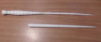
Making a DVB-T2 (UHF) antenna amplifier with your own hands.
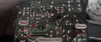
The board can be made without etching by simply cutting out the pads. Let's look at the drawing.
We make the board from double-sided fiberglass. We connect the top and bottom layers with four pins and solder them.
I used a transformer power supply to reduce noise, with voltage stabilization at 12 volts. The amplifier consumes about 12mA.
Everything worked fine for me right away without any setup. The setting involves selecting resistors R1 and R3 so that the currents on the collectors of transistors VT1 and VT2 are 3.5 mA and 8 mA, respectively.
Conducted tests at work. In the depths of the room. Yard well. As an antenna, a piece of SHVVP wire. The result without an amplifier shows nothing at all. I connect the amplifier and, as they like to say in advertising, the result exceeded all my expectations, a stable picture without a hint of failure.
List of parts for a homemade DVB-T2 antenna amplifier (UHF).
Transistors BFR193 - 2 pcs. (can be ordered from the Chinese here). Capacitors 3.3pF, 10pF, 100pF - 2 pcs., 4700-6800pF. Resistors 75 KOhm, 150 KOhm, 1 KOhm, 680 Ohm. Choke 100-125 µH. Homemade coil L1 2.5 turns and 4 mm in diameter from copper wire 3.5 cm long and 0.8 mm in diameter.
Varieties
Despite the variety of equipment of this type, amplifiers can be divided into the following types according to their functionality and range:
- Devices operating over a wide range. As a rule, they are used for external mast antennas of the lattice type. Wideband antenna amplifiers SWA (1), LSA (2) and Gal (3)
- Equipment tuned to a specific range, such as meter or decimeter. An example is devices for digital television antennas in DVD format T Digital signal amplifier
- Devices operating with several ranges. They can receive signals coming from several sources and combine them into one. Or, conversely, form several signals from one signal, as is done in ALCAD AI-200.
Home amplifier ALCAD AI-200 with splitter and built-in power supply
Antenna at 855 Hertz
According to estimates, the size of the antenna will correspond to the European 69th channel, which includes Russia. Television is shown at a frequency of 855.25 Hertz, and sound is shown at 861.75 Hertz. According to calculations, its antenna circuit is tuned to 857 Hertz. The design will require a large piece of 75 ohm cable. We make a ring with a gap from 54 centimeters, we will take a signal from it
Please pay special attention that the screen in this version is a signal one. We attach a matching U-elbow made of 75 Ohm wire to it, the size of half a wave – 175 millimeters
It goes like this:
- one end of the core inside the U-elbow wire is seated on the signal wire connected to the receiver and on one of the parts of the screen;
- the other end of the U-elbow wire strand is seated at the other end of the screen.
As a result, the added part of the line equalizes the resistance of the wire connected to the receiver and the circular circuit. In order to make a UHF digital antenna from this design, it must be adjusted to the multiplex frequency
. How to do this is probably already clear, but we will describe in detail:
- The size of the U-elbow is half the size of the multiplex wave.
- The frame size is equal to ¼ multiplex wavelength.
The multiplex wave size can be found on the Internet or local publications. To obtain vertical polarization, the frame must be rotated at a right angle with a gap to the side. In this case, you can also catch the signal from walkie-talkies. These are the simplest external antennas.
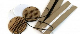
Parts and PCB
The amplifier elements are placed on a printed circuit board made of double-sided foil fiberglass; the pattern of the printed tracks and the arrangement of the elements are shown in Fig. 3.
The second side of the printed circuit board is left metallized and is connected along the circuit with the common conductor of the first side. For the automotive version, the printed circuit board should be extended so that a relay and power filter can be placed
In the amplifier, it is desirable to use a low-noise transistor with a normalized noise figure; the KT3120A indicated in the diagram is best suited, as well as KT382A, KT382B, KT399A, KT3101A-2, KT3106A9; it is possible to use the KT368A transistor, but the results may be slightly worse. Capacitors KD, K10-17 and similar imported ones, S9 – K10P 4 K10-51 KTP, B23. Resistors – MLT S2-33, R1-4.
Rice. 3. Printed circuit board for VHF antenna amplifier.
Coils L1 and L2 are wound with PEV-2 0.4 wire on a mandrel with a diameter of 4 mm and contain 3.5 and 4.5 turns, respectively. Coil L3 is wound on a ring with a diameter of 8-10 mm made of ferrite grade 2000NN and contains 20-30 turns of PEV-2 0.2 wire.
The amplifier is connected between the antenna socket and the radio input. In this case, the connection from the amplifier to the receiver input must be made with a short shielded cable.
When installing in a car, all connections should be made with a shielded cable, and the amplifier should be placed near the radio in a shielded compartment.
If the amplifier is switched (car version), then a power switch is needed, which is placed in any convenient place.
The filters are designed to work on a cable with a characteristic impedance of 50 Ohms; when working on a 75 Ohm cable, it is necessary to reduce the capacitance of capacitors C1-C4 and increase the inductance of coils L1 and L2 by one and a half times.
DIY antenna amplifier diagram and description
The one below shows how it should actually connect to the TV. The TV cable itself passes through the amplifier board, and only then the signal enters the TV.
When making an antenna amplifier with your own hands, you will not need any special materials - mainly, you will need to purchase radio-electronic components, the location of which is shown in the diagram. T1 transistor 2sc3358 - one of the main parts of the circuit of the future device C1 - 10mF / 35v C2, C9 - 1nF C3, C4 - 10 nF C5, C6, C7, C8 - 10 pF - capacitors for surface mounting Resistors R1 - 470 Ohm R2 - 2.2 kOhm, R3 - 1 kOhm, R1 - 5 kOhm Elements L1, L2 - 2 turns 0.5 mm, 3 mm. L3, L4 - 10uH or 10 turns, 0.2 mm on ferrite. 12 volt power supply. On request – with adjustable voltage supply.
Amplifier PCB:
Once again, pay attention to the power supply - 12 volts, which means the need to use capacitors when connecting the assembled device to the power supply. Also, a do-it-yourself TV antenna amplifier can be powered using the antenna cable itself (coaxial cable) if the required voltage is available
After assembly, the board looks like this:
Adjustment of the manufactured amplifier is carried out by moving resistor R1 to the middle position, and then adjusting it after it has been possible to obtain a normal image on the TV screen. After the antenna with amplifier has been assembled and tested with your own hands, you can and should place it in a small metal box, which, in addition, will shield the device from extraneous radiation.
The given method is not the only one possible. With absolutely the same basic diagram, it is permissible to change the elements used in it - this will largely depend on the strength of the signal coming to the television antenna. In turn, the signal is attenuated when passing through the antenna cable - the longer the cable, the weaker the output signal will be. Based on this, you need to take into account the signal strength and decide how much amplification you need. For example, with a signal level of 10 dB, the best device is one that can increase its strength by 2-3 times.
There are also cases where one station transmits a much stronger signal than another, and too powerful an amplifier causes them to overlap each other. This can help by reducing the supplied voltage, for which you should use a power supply with the ability to regulate power. In addition, you can immediately assemble a fairly powerful device, and only then adjust it to your needs, reducing or increasing the voltage supplied to it.
Making an antenna that doesn't need amplifiers
We must warn you right away - if the distance to the TV tower is more than 15 kilometers or there are a large number of obstacles in the path of the signal, then you cannot do without an amplifying device. If there are no problems described above, then the antenna can be made in about 10 minutes.
Step-by-step algorithm:
- The first thing you need to do is find out what channel the signal is broadcast on in the region. Open the link www.rtsr.ru and go to the RTRS web page. Then we indicate our current location.
- Scroll down and find the phone number by which the user can find out the broadcast channel.
- We enter the channel data in the appropriate field that will appear when the TV is switched to manual tuning mode. The frequency that will be needed to calculate the cable length will be displayed below.
- Then we take a calculator. To calculate, we use the following formula: 7500 divided by the frequency in MHz. We always round the result up.
- For example. Frequency in the Samara region is 754 MHz. Divide 7500 by 754 and get 9.9. This means that the cable length must be 10 centimeters.
- Initially, there is no need to shorten the cable. We install a simple television connector on it, which is connected through a coupling to the cable.
- Next we take measurements. We retreat 20 mm from the plug. There will be a bend at this point. This is where you should measure the required length. In our case it will be 12 cm (2+10=12). Next, the cable is cut at the outermost mark.
- Then remove the insulating layer from the 20 mm mark. to end. This is very easy - modern cables have a very soft outer layer.
- Afterwards we remove the shielding layer. We don't need him at all.
- At the 20 mm mark. The cable is bent at an angle of thirty degrees. After this, the antenna is ready for use.
- We position the antenna so that it is directed towards the TV tower. There is no need to hang it outside the room. In the room the signal, although lower, will be quite sufficient for normal reception.
To summarize all of the above. Without an amplifying device, you can make a TV antenna yourself. In this case, such an antenna will function at the level of the factory analogue.
Instructions on how to make an antenna
The installation of any horizontal type antenna begins with the selection of a support to which we will subsequently attach the insulators. The first support should be on the roof of the house, and for the second you can choose a tree with the appropriate height. We attach the insulators to the racks using steel cables.
Roller blocks are used to reduce vibrations. To use them, you need to fix a small weight on the opposite end of the wire, connecting it to the antenna.
The receiving element of the future antenna must be a solid fragment made of a single material. If there is no whole piece of wire, then you can combine several elements from a single material by stripping and soldering with tin solder.
The mount for the vertical receiving element of the antenna is a stand that prevents the wire from changing position during strong winds.
Making a signal amplifier with your own hands
Consider the circuit of a simple antenna amplifier. Its entanglement begins from a power source with a voltage of 2.8-5.2 V. A device using this circuit is characterized by almost silent operation (the noise produced is only 2 dB) and has a fairly high gain (approximately 13 dB).
Work order:
- Prepare all the required electronic stuffing.
- Organize your tools and supplies.
- Make a printed circuit board. Moreover, it is better not to use a hinged assembly and special mounting panels, otherwise the device will produce too much noise during operation.
- Solder all electronic components.
- Check the resulting device carefully.
- Connect it to the antenna and receiver.
As for the power source, a more detailed description of how to make a power supply for an antenna amplifier can be easily found on the Internet.
How to connect and configure an antenna amplifier
If the circuit is assembled correctly based on correctly selected components, then there is no need to make any adjustments. Antenna amplifier for TV signal between the splitter and TV receivers. If you need to supply power to it, you need to think about such a power source in advance.
An active antenna can also be passive, and this is very simple to do. To do this, you just need to unplug the power supply from the outlet.
How to improve the signal. Video
The video below will tell you how to improve the signal of a television antenna.
It is better to purchase factory-made antennas and TV amplifiers, since they are made according to calculations. If you make the devices yourself, their quality will be an order of magnitude lower. For TV reception in the countryside, it is necessary to have high-quality devices due to the distance from the television center and the presence of a large amount of interference.
The transmission range of television signals is limited by the characteristics of carrier waves, which weaken with each kilometer of distance. In areas located far from television towers, or located in areas with difficult terrain, the signal arrives weakened, which results in poor reception of some channels.
Making an antenna amplifier yourself will help correct the situation. Its only difference from a purchased one will be the price, but not the quality of reception. In addition, having once mastered its creation, you can mount such devices yourself in the future.
TV antenna amplifier - what is it?
If you look at it, a TV antenna amplifier is not a very complicated device. This is a simple microcircuit designed for a power supply of six to twelve volts. Sometimes it doesn't even need an internet connection. Question: what causes the signal to be amplified? We will understand this without using complex terms and definitions.
The signal enters the transformer from the antenna and is then sent to the transistor. In a transistor, the TV signal is amplified, and only slightly. Then its path lies through the emitter. Then, using cascade transistors, the frequency is adjusted. This is a simple description of a complex thing at first glance. After this, the signal is sent to the TV.