This is my first four-legged robot project. The development of the first version lasted about a year, the latest modification is already the fourth. There are two versions - for servos sg90 and mg90. If you are interested in the history of the development of the project, you can look at it on the blog.
Two more projects related to the spider are a simulator in vPython and remote control using Bluetooth. They will be discussed in the second and third parts.
This spider is fun to make, but it will take time and patience to complete.
You can download all the necessary files from this link.
Necessary parts and components
Before you start assembling the quadcopter with your own hands, you need to acquire all the necessary parts. The brain of our homemade product will be the Arduino Uno flight controller. Its capabilities are more than enough to control a drone.
In addition to the microcontroller, we will need:
- Battery (preferably several) 3.7V
- MPU-6050 board (gyroscope and accelerometer installed on it)
- Transistor ULN2003A
- Commutator motors with hollow rotor 0820
- Wires
A few points need to be made. Since we are assembling a cheap homemade drone, our choice fell on commutator motors with a hollow rotor (the so-called coreless motors). They are not nearly as reliable as brushless motors, but they are much cheaper. In addition, you can do without additional speed controllers.
But it is impossible to do without a gyroscope and accelerometer. The gyroscope is necessary to ensure that the quadcopter can maintain a given direction of movement, while the accelerometer is used to measure acceleration. Without these devices, controlling the copter would be much more difficult (if not impossible), since they provide data for the signal that regulates the speed of rotation of the propellers.
We did not include the frame in the list of required parts. You can purchase it, or you can 3D print the frame, beams and mounts for the engines. The second option seems preferable to us, especially since you can easily find quadcopter projects on the Internet.
The frame printed on the printer will be not only light, but also durable. But if you don’t have access to a 3D printer, you can order a frame.
Bill of materials
| № | Name | Qty |
| 1 | Arduino UNO board | 1 |
| 2 | Expansion board for connecting servos and power supply iArduino Multi servo shield | 1 |
| 3 | Servo motors with metal gear SG90s | 8 |
| 4 | Battery compartment 18650×2 | 1 |
| 5 | Lithium 18650 batteries | 2 |
| 6 | IR remote control | 1 |
| 7 | IR sensor | 1 |
| 8 | Jumpers Dupont connector - connector (female - female) 10 cm | 3 |
| 9 | Wires | 1m |
| 10 | Tumblr | 1 |
| 11 | Set of wooden parts for assembly | |
| 12 | M3 x 10 countersunk screws | 40 |
| 13 | M3 x 12 screws | 16 |
| 14 | M3 x 16 countersunk screws | 4 |
| 15 | M3x10 countersunk screws | 2 |
| 16 | M3 self-locking nuts / Nylock | 17 |
| 17 | Nuts m3 | 45 |
Table 1 List of components for assembling a robot - the Quadruped spider
HEXAPOD or spider robot as a way to automate construction work.
Over the past few decades, the development of science and technology has reached great heights. Due to the rapid development of robotics throughout the world, it has become possible to simplify, speed up and automate many processes that previously required a lot of labor and risk.
The construction of buildings and structures requires careful preparation. This requires a large number of highly qualified specialists in the field of construction: architects, geologists, surveyors, masons, electricians, etc. Many of them, when performing work, are exposed to hazardous factors, such as an aggressive environment, high-altitude work, and difficult climatic conditions. All this requires high labor costs, material investments and risks.
Currently, the task of progressive construction is to automate processes and increase the productivity of hazardous and high-precision work.
I propose a radically new way of carrying out some work during the construction of objects. To automate these processes, a robotic automatic device called a hexapod will be used, with a manipulator attached to it, which will carry out certain work.
Thanks to plantigrade movement, this robot will be able to move on various types of surfaces, climb heights and manipulate various modules with great precision.
The manipulator on the hexapod is used to grab objects and move them in space. Various installations can also be attached to it, for example, for pouring floor screed or foundations, for drilling or drilling, or a welding machine. Thanks to built-in sensors, such as infrared, ultrasonic or optical, the hexapod will be able to navigate not only during the day, but also in the dark. Using specially developed software, the robot will build a three-dimensional model of the landfill (the area where construction is taking place) and will report in real time about the construction process using the MQTT protocol or other means for data transmission.
Due to modular construction (the use of modules from which a structure is assembled, which is reminiscent of assembling a construction set), assembled using various installations, the hexapod will be able to literally assemble and connect modules to each other. Due to the fact that the hexapod has several types of gait and control modes, it can act both as a crane and as a cargo carrier.
Currently, automation of various types of work is important. This is cheaper than hiring many workers, significantly speeds up the process and increases its accuracy. Technologies of the 21st century make it possible to create powerful mechatronic devices that will perform most of the same type of work that requires a person’s time, concentration and risks to life. Of course, at the initial stage of development, a large amount of material investments is required, but with the mass production of robots and their improvement, their production will also become cheaper.
This model uses a larger number of drives, an improved leg model and platform, increasing mobility and flexibility. This robot uses an Arduino mega 2560 microcontroller, an advanced power circuit and wireless control. To create this project, it was necessary to purchase a 3D printer, a multimeter and various CAD tools that combine the project development processes. At the moment, there is no manipulator installed on the hexapod, but there is a mounting location for it, as well as a power reserve and the computing power of the control controller.
3D printing
To produce the hexapod parts, an FDM (Fused Depsition Modeling) 3D printer Flying Bear Ghost 4s was purchased. This printer is one of the best in its price category. It prints with PLA, Pet-G, ABS and others. The good kinematics of this printer prevent damage to parts during printing. A specially heated table improves adhesive properties for better adhesion of the part to its surface.
PET-G was chosen as the main material for manufacturing since its physical and mechanical properties are excellent for hexapods. The dampers were printed from Bflex material.
Slicer - Cura.
To improve the quality of printed models, the design of the printer was improved. Instead of the originally installed bowden extruder, a direct one was printed and installed. The PID for the table and heating element has been calibrated, the steps for the extruder motor have been calibrated, the drivers for stepper motors on the X, Y, E axes have been replaced. The thermal chamber was assembled from the top box (plywood) and the front door (acrylic), the stock glass was replaced with a 3mm mirror.
The shrinkage coefficient was also calculated for accurate hole printing.
Read more about creating this hexapod model
Development
Hexapod 3d model:
The robot was developed on the basis of similar existing models, including hexapod robots. As a result of the work, various modules were significantly improved and the design of the legs was improved, which required the use of 18 servos. This made it possible to increase the mobility and flexibility of the robot. Drawings and models of robot body parts were completely developed in a CAD system and produced using additive technologies
. 3D models can be used to make technological calculations and be used in further production.
At the ends of the legs, damper tips of our own production were developed and installed. They are a plastic case with a spring inside. The tip prevents breakage of the leg elements during an impact, reduces the load on the servo gearbox shaft and eliminates its deformation and wear, and also eliminates strong knocking during movement. The design of the platform has been improved, making it possible to install a manipulator, a cooler for cooling, as well as a stabilizer for an FPV camera.
The hexapod uses an Arduino mega 2560 microcontroller with an additionally installed Raspberry pi 4. This allows you to move the robot smoothly and with great precision. The following were also improved: the power supply circuit, which made it possible to turn the robot on and off using a controller, and wireless control, which controls the movement of the robot, the manipulator, and camera control. It is possible to connect to the hexapod remotely via Wi-Fi data transmission, and you can also expand the functionality and control the mechatronic device remotely. The robot is manufactured to industrial standards to avoid injury, it has an emergency stop button, and all electronics are housed in a housing. An LED indicator for debugging and displaying the status of the robot is assembled and shown in the photograph.
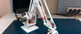
Manipulator
One of the main parts of the hexapod is the manipulator. It is made of PET-G plastic using a 3D printer. The manipulator and its kinematics were designed in a CAD system according to our own drawings and developments. The manipulator consists of 3 links and a gripper, which rotate in the same plane. Servo drives are used as motors, the torque of which is >10 kg/cm. The manipulator is capable of lifting objects weighing up to 500 grams and up to 1000 in holding mode. The robot is also equipped with an FPV camera, which allows you to control the robot remotely, and a machine vision camera, which provides object recognition and subsequent display of them on the monitor.
Programming
Programming was done in the Arduino IDE and sublime_text development environment. The code consists of functions that control modules and functions that control them. The program implements emergency stops and error output when the connection is incorrect or when the body tilt deviates from the norm. >60% of software was developed manually.
Control
To control the hexapod, a PlayStation2 gamepad with a receiver is used. It allows you to precisely control movement, select different gait types and select control modes. Wireless control is implemented using a built-in 2.4Hz radio module. The receiver is installed on the top of the hexapod body platform and connected to the Arduino mega (pins 2-5 are used for signal transmission, as well as pins 3.3V and Gnd for power).
Power
Li-ion batteries are used as a power source for the hexapod. To stabilize the voltage, an SBEC on-board voltage stabilizer is used.
Batteries
The batteries used are li-ion batteries of the 18650 format. The advantages include:
— High energy density.
— Low self-discharge.
— No memory effect.
— Ease of maintenance.
— Low specific gravity.
The batteries are assembled in series into a 3s battery (12.6V).
Stabilizer
The on-board voltage stabilizer YEP 20A HV (2 ~ 12S) SBEC is used as a stabilizer. Due to the fact that on each servo drive the voltage drop reaches 0.3 V, in total, from all motors, the voltage drop takes a value of up to 6 V, as a result of which many drives do not work. Also, each drive consumes up to 800mA; it was experimentally determined that the total current consumption is approximately 15A.
Based on the above problems, the stabilizer must meet several requirements:
• Maximum current 20A
• Output voltage 5-7.2V
• Have a heat sink
The on-board voltage stabilizer YEP 20A HV meets these requirements
(2~12S)SBEC.
specifications:
- Current: 20A
- Input voltage: 2-12S
- Output voltage: 5V / 5.5V / 6V / 7V / 9V
- PCB Size: 57x26mm
- Weight: 42g
Video of the hexapod in action
#3dmay
Video demonstrating the robot in action
I found another video on YouTube (one of the most popular in this topic), which discusses the creation of a robot that avoids obstacles. It is more advanced than the one discussed in this article thanks to the ultrasonic sensor rotating with the help of a servomotor. It also contains the source code of the program (available via the link from the video description), but without explanation. But, I hope, the explanation of the program of the robot discussed in this article will help you understand the program code of this more “advanced” robot.
Hello! If you are interested in what will happen in the end, read the final part.Due to various circumstances, the release of the third part was delayed and yes, we will talk about ESP8266 firmware in the ARDUINO environment. I’ll say right away - I’m not an Arduino guy, this is the fourth time I’ve encountered this environment (three projects from one resource).
Let's start by installing the environment and libraries. The environment can be downloaded from this link. This is a portable version 1.8.5 in a zip archive. We unpack the archive into c:\Program Files\ - that’s it, the environment is installed. Let's move on to installing libraries. To do this, follow the link and do everything that the author writes (I won’t say better how it’s written there, but I don’t see the point in rewriting). Select library version 2.4.2. As a result, we will install libraries for ESP8266 and drivers for CH340G. Now again select the menu item Tools → Board: “Arduino/Genuino Uno”
and select the “Generic ESP8266 Module” board:
Set the settings as in the picture above. Everything is ready, you can flash it.
We open the source code that we downloaded earlier and see that everything is in English and Chinese, respectively, and the control buttons will be in English. This can be seen in the video from the article. Personally, this doesn't suit me. And you? Then open Google Translate and go ahead.
We connect the board to the PC and before applying power to the board, we close GPIO0 to ground, as in the photo:
The LED on the module will blink three times and go out, you can open the output. Click the Download button:
If everything went well, it will look like this:
If you don’t want to bother with Arduino, you can flash it using ESP8266 Flasher. To do this, download the archive at the end of the article and do everything according to the instructions.
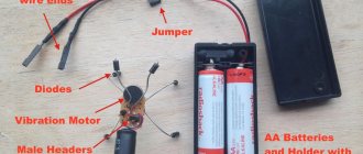
For the convenience of connecting the servers, I signed them according to the diagram (top view):
The board was flashed, the servos were connected, all that remained was to connect the boost module and the battery charging module (links to which were given in the second part) along with it. I found an even smaller boosting module in my bins:
By the way, about the connectors where to connect the module:
We solder the connector, then heat-shrink it so that nothing short-circuits and put it in place:
During the “field” tests, it turned out that the battery-powered robot does not work. The reason was an incorrectly routed power supply. It was like this:
You need this:
We take a knife and a soldering iron and fix it:
Where it is black we cut it, where it is red we connect it. This is what happened to me:
Now let's move on to the charge module. We solder the connectors for connecting to the board and the battery, wires to indicate the charge, end of charge and discharge of the battery, and glue double-sided tape:
At the same time, we are modifying the battery:
We connect the charge board, glue it and solder the remaining wires:
That's it, now you can screw the bottom cover into place:
In the first part I said that there will be two toys. So here it is. We take the robot's eyes from version 2.0, color them and glue them to the top cover:
We connect the battery to the connector, place it in the cover (or glue it to it with double-sided tape if the battery is smaller than what I used) and screw it on:
That's it, now you can try to “revive” our spider. Looking ahead, I will say that it is better to start doing this by charging from a phone/tablet or an external battery (Power Bank) with an output current of 2A. We connect the “cord” to the board, supply power from USB, go to the Wi-Fi settings on the phone/tablet and see our network:
To connect to the GOSHA 1.0 - 5F57 network, where 5F57 is the MAC address of a specific module, you need to enter the password 12345678 . If you want to change it, in the source code, look for the line const char WiFiAPPSK[] and change it.
Open the browser on your phone/tablet and enter 192.168.4.1 in the address field and press enter. The page will load:
In general, if you add one of the lines /setting, /zero, /editor to the address, the following pages will load:
What are the remaining pages for? To set the servo positions. So.
/setting – this is the setting of the zero state of the servos,
/zero – this checks the zero state of the servos,
/editor is the motion editor.
As they say: “It’s better to see once...” Video on setting the zero position of servos from the author of the robot:
And finally, a video of what happened in the end:
That's all! Good luck with the assembly everyone! If you have any questions, write.
PS Due to the identified shortcomings, the board was slightly redesigned:
PPS It was decided to move the charge controller to the board:
This circuit was taken as the basis for the charge controller:
The discharge indicator is assembled according to the following scheme:
All versions of the boards can be downloaded at the end.
PPPS During operation, some aspects of the operation of the charge controller (more precisely, the discharge/overcharge protection unit) were found, namely, protection during a sharp load jump (all servos consume 1.6A at the peak). To avoid this, before applying power, I manually transfer the spider’s legs to the zero state (you can see it in the video), and start control with the “Wait” or “2nd dance” button.
PPPPS I ordered boards for Power Bank with 5V/2A output in China. After arrival and verification there will be an addition to the article.
First part.
Second part.
Software
The main framework of the software was already written in a previous project, see the article “Robot Ant: Programming”. The main changes are related to the transition to the new STM32F407VET6 microcontroller. I also discovered a bug related to the rotation algorithm. In the previous version, when turning, the robot seemed to trample from foot to foot. Those. takes a step, then moves to the starting position, etc. In general there is no continuous movement. The old version can be viewed here. In the new version I fixed this, the spider robot gracefully spins in place around its axis.
After calibration of the limbs, he can walk in different directions and at an adjustable speed. Move your body and rotate it. Sit down and stand up. And much more!
All necessary files (firmware, remote control, instructions) can be downloaded below:
- firmware for STM32F407
- robot control panel
- calibration instructions
You can see how to assemble such a robot yourself in the video below.
Four-legged robot based on ESPduino. Start.
Hi all! Did you spend a lot of money on the sale? I'll try to break up the holiday fever with a DIY project. Somehow, while digging through thingiverse in search of interesting models and inspiration, I came across this robot. The flow contains several automatic algorithms, plus control via wifi via a computer, phone or controllers. I decided that I just needed to collect the same one. I went to the official website and was depressed - the original filling costs $88, but is built on the basis of ESP, which means there was a chance to build an analogue cheaper, especially since the sketches are in the public domain. The parcels have been received, the main components have been assembled, but we need help with the ESPduino. If I can flash it, I’ll remake the model for a new board and anyone can build an analogue for less than $40, besides, there’s plenty of room for customization. I can send housing details to active participants if you agree to pay at least shipping =) Details are under the cut. Website of the original project: jbotq1.blogspot.ru/search/label/shop I hope the administration will not consider it advertising, the information is just for informational purposes =) ESPduino board with shield (16 servos and 2 motors) from here for $19.99 Modified software for firmware I bought 8 servos from here, 2 sets cost about $20 Case models from here I printed all the parts in several passes (the coating foamed due to my impatience - there will be more posts about this).
I liked the joints - fastening the drives without a single bolt, the edges bend after heating and the servo is inserted into the grooves. Anyone can handle assembling the case; all you have to buy are a few screws for attaching the upper and lower parts to the frame.
True, you still need to glue the lower bushing
The drives are attached to the leg and body using complete screws. Sorry for some of the unclear pictures - draft.
With closed bottom
It turned out that the ESPduino board is a little larger than the original one, but these are minor things - I can easily remake the mounts and everything will be like original. I haven’t worked on it yet because I encountered a problem when uploading the sketch. The official set with instructions, sketch and software was posted here ATTENTION! The assembly at this link uses a regular arduino IDE, I didn’t remove it, maybe you need the complete version.
Currently in the process of preparation and assembly in the form of a draft. I ask for your help in finalizing the project, I can provide remote access to my computer with a connected board and camera for tests to check functionality.
If everything works out, I will remake the 3D models, put all the necessary material in the archive, shoot a normal video manual on assembly and configuration, duplicate it in a full-fledged classic review and will gnaw on the forums in the direction of improving the existing functionality (proximity sensor, backlight, camera), there’s a ton in the shield space for additional servos and motors. Well, for now it’s like this:
This is what it should look like (demo)
The sketch was compiled and uploaded, the web interface came out, the servers are not working yet, but I feel the revival is close. Thank you
andreyMOZ
for help with the correct setup of the Arduino IDE
UPD.
There are very few examples of working with this board on the Internet, although it is successfully sold on many sites. At the moment, the problem with the response of the servos remains. I tried to connect the servo directly to the ESPduino - silence, although the sketch is uploaded without errors, but only when choosing a generic esp8266 board instead of ESPduino (ESP-13), the access point and web interface opens.
UPD2
. The serfs have come to life! The code is being reworked to use the shield; if it works, we will have a lot of pins freed up for additional wishlists.
UPD 3
— The sketch has been redone! Many thanks to andreyMOZ for the work done, I suggest giving him some pluses =) But there is still one small problem left. During the experiment, 3 servos died. I broke one due to inattention and using single-color wires as an extension cord; most likely they left us due to overload, because... were jammed before the diagnosis was announced. I have not encountered any repairs, if anyone has experience, please share. I have ordered another set of 4 servers, I hope they will be delivered promptly. After assembly and testing, I will post a guide for assembly and configuration from scratch.
UPD4
A second article with a complete assembly is being prepared. What’s ready: — The case was redrawn and printed for the boards used. — The sketch has been redesigned for a standard shield. — The test model is assembled and functions almost like the original.
What is not completed: — The bottom and top covers have not been redrawn. Not critical, but the appearance differs from the standard. I have problems with modeling smooth shapes)) so if anyone has the time and desire, write to me in a personal message, I will provide all the necessary data (dimensions). — The smooth movement of the limbs is not the same as that of the standard, but this is a software issue that can be solved cooperatively after release =)