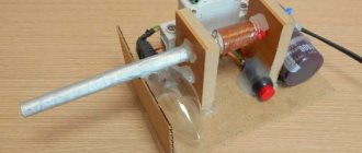
Hello Giktimes! I would like to share with you the results of reverse engineering uArm - a simple desktop manipulator made of plexiglass with servos.
The uArm project from uFactory raised funds on Kickstarter more than two years ago. They said from the very beginning that it would be an open project, but immediately after the end of the company they were in no hurry to publish the source code. I just wanted to cut the plexiglass according to their drawings and that’s it, but since there were no source materials and there was no sign of it in the foreseeable future, I began to repeat the design from photographs.
Now my robotic arm looks like this:
Working slowly in two years, I managed to make four versions and gained quite a lot of experience. You can find the description, history of the project and all project files under the cut.
Plexiglas cutting
We order plexiglass cutting from a company located near Yekaterinburg. They do it quickly, efficiently and do not refuse small orders. Cutting such parts will cost about 800 rubles. As a result, you will receive cut out parts with plastic film on both sides. This film is needed to protect the material from scale formation.
Plexiglas part with film
This film must be removed from both sides.
Item without film
We also ordered engraving on the surface of some parts. For engraving, simply draw the image on a separate layer and indicate this when ordering. The engraving areas must be cleaned with a toothbrush and wiped with dust. It turned out very well:
Engraving on plexiglass
As a result, after removing the film and grout, we got this:
Roboteurs RBX1
This is another great 3D printed robotic arm that has amazing flexibility and aesthetics. In addition to purchasing the components yourself, Roboteurs offers a complete parts kit with a proprietary stepper motor driver to run the RBX1. All you need is a Raspberry Pi and a 3D printer. This arm is a 6DOF design and has a beautiful appearance.
You can find the entire specification and parts kit on the Roboteurs product page.
Main characteristics
When making a homemade crane beam, it is better to focus on the technical parameters of factory-made models. These characteristics were calculated by qualified specialists, so they are optimally suited for multi-purpose use.
The characteristics of different modifications may differ, but in general, it looks like this:
- Work zone. The span length varies between 3-28.5 meters. You should not focus on this indicator: not every garage has such an area, so the length of the crane runway is selected based on the actual size of the room.
- Lifting height. Industrial lifts lift loads to a height of 6-18 meters. For private use, you can stop at the minimum option. For example, if we are talking about a simple hoist for a tractor or a passenger car, a lifting height of 1.5 meters is sufficient.
- Voltage. Electrical equipment operates from a three-phase network of 380V. If you intend to install a manually operated lifting device, this parameter is not relevant.
- Operating temperature range. Factory models work correctly at temperatures of -20/+40 degrees. This parameter must be taken into account when choosing components.
How to make a homemade crane in the back of a truck with your own hands - let's cover it step by step
A loader crane is a power unit mounted on moving platforms. She lifts and carries heavy loads in a short period of time. You can make such equipment yourself and install a homemade crane in the back of a truck.
Create an account
Register for an account. It's simple!
Technical characteristics of the result
A sample with length/height/width parameters of 228/380/160 millimeters, respectively, will be considered. The weight of the finished product will be approximately 1 kilogram. A wired remote control is used for control. Estimated assembly time if you have experience is about 6-8 hours. If it is not there, then it may take days, weeks, and with connivance even months for the manipulator arm to be assembled. In such cases, you should do it with your own hands only for your own interest. To move the components, commutator motors are used. With enough effort, you can make a device that will rotate 360 degrees. Also, for ease of work, in addition to standard tools like a soldering iron and solder, you need to stock up on:
- Long nose pliers.
- Side cutters.
- Phillips screwdriver.
- 4 D type batteries.
Robo hand. Assembly of mechanics
We have developed a robotic hand that anyone can assemble on their own. In this article we will talk about how to assemble the mechanical parts of our manipulator.
Note! This is an old article! You can read it if you are interested in the history of the project. Current version here.
Manipulator from
Here's a video of her working:
General description of the robotic manipulator project
The project uses 6 servo motors. For the mechanical part, acrylic 2 mm thick was used. The base from a disco ball came in handy as a tripod (one of the motors is mounted inside). An ultrasonic distance sensor and a 10 mm LED are also used.
An Arduino power board is used to control the robot. The power source itself is the computer power supply.
The project provides comprehensive explanations for the development of a robotic arm. The issues of power supply of the developed design are considered separately.
Links
Files for cutting plexiglass, 3D models, a purchase list, board drawings and software can be downloaded at the end of my This article is an introductory guide for beginners on creating robotic arms that are programmed using Arduino. The concept is that the robotic arm project will be inexpensive and easy to build. We will assemble a simple prototype with code that can and should be optimized; this will be an excellent start for you in robotics. The Arduino robotic arm is controlled by a hacked joystick and can be programmed to repeat a sequence of actions that you specify. If you are not strong in programming, you can take on the project as a training for assembling hardware, upload my code into it and gain basic knowledge based on it. Again, the project is quite simple.
The video shows a demo of my robot.
Features of the manipulator
Before the advent of uArm, desktop manipulators of this class looked rather dull. They either had no electronics at all, or had some kind of control with resistors, or had their own proprietary software. Secondly, they usually did not have a system of parallel hinges and the grip itself changed its position during operation. If you collect all the advantages of my manipulator, you get a fairly long list:
- A system of rods that allows powerful and heavy motors to be placed at the base of the manipulator, as well as holding the gripper parallel or perpendicular to the base
- A simple set of components that are easy to buy or cut from plexiglass
- Bearings in almost all components of the manipulator
- Easy to assemble. This turned out to be a really difficult task. It was especially difficult to think through the process of assembling the base
- The grip position can be changed by 90 degrees
- Open source and documentation. Everything is prepared in accessible formats. I will provide download links for 3D models, cutting files, list of materials, electronics and software
- Arduino compatible. There are many detractors of Arduino, but I believe this is an opportunity to expand the audience. Professionals can easily write their software in C - this is a regular controller from Atmel!
Installation of crane installation
- The subframe can be welded from outer (18 mm) and inner (16 mm) channels. Before doing this, bend the planks so that they follow the shape of the frame. Insert the smaller rail into the larger channel, they should form a rectangle.
Then weld the structure along its entire length. Subframe length – 70-980 cm under the crane boom + body size. Cut what you need after fixing the body. This way you can adjust its position. - Using stepladders, attach the prepared channels to the frame. Place a fire hose between them and the base. It is needed to align the planes of the planks and frame. To ensure that the subframe under the faucet is solid, weld the channel using a piece of corner. Weld it over the cross member of the base so that you can then bolt the channel to it.
- . It comes with special stepladders.
Use them to secure the faucet. Be sure to insert special spacers into the stepladders. - You can make spacers as follows. Take a piece of pipe with a diameter slightly larger than the cross-section of the stepladder. The length of the pipe should be half the height of the frame. Cut a rectangular piece of plate 7-10 mm thick. The smaller side of the segment should have a size of 7-9 cm, the larger side should fit snugly in height inside the frame. Weld the pipe to the plate in the middle. Next, tighten the stepladders tightly.
- To prevent the manipulator from moving along the base, weld corners measuring 4x4 or 5x5 cm to its subframe perpendicularly from the back and front.
- Now you can install the body on the gazelle. At the same time, leave a gap of 15-20 centimeters between the body and the truck crane. Secure the body cross members with bolts.
- Your faucet is installed. All that remains is to connect the hydraulic pump, with the help of which the manipulator will operate.
First, general issues will be discussed, then the technical characteristics of the result, details, and finally the assembly process itself.
Assembling a robot arm
To begin assembling the linkage, start by bolting all the servos using M3 screws. Since the lever requires a lot of torque, high torque metal gearboxes were used to handle the weight of the lever. The bottom 5 servos (turntable, arm (x2), elbow and wrist) are SAVOX SC-0252MG servos which produce 10.5 kg/cm torque at 6 volts. Wrist Servo - Standard Fubata S3003 servos which produce around 3.5kg/cm. All servos (except wrist pivot) have a metal gear and double metal bearing which ensures they are physically strong as a lever will put a lot of pressure on them.
Once installed in the servo brackets, they are then connected to the C brackets. Mounted on one side is the cross-shaped servo head that comes with the servo. They are cut to size and then bolted into place. On the other side of the bracket, the flange bearing is attached to an 8mm hole, which is then bolted through the bracket using an M3 screw and nylon nut to prevent the nut from coming loose when rotating. If the M3 screw is a little longer, you can use 2-3 M3 washers on the outside of the bracket to make sure it doesn't cut into the back of the servo.
The bearings have an inner diameter of 4 mm, an outer diameter of 8 mm and a thickness of 3 mm. These bearings are flanged and have a small metal lip on one side that prevents them from being pushed through the bracket. This type of bearing is quite common in remote control car models and can be purchased either from a specialty store or from Aliexpress. There are 4 bearings in total, 3 in the bracket and one in the end grip.
Construction of the grip
The end gripper design is based on two counter-rotating gears that use leverage to open and close the grippers laterally. This allows the design to use relatively small parts, but the open hole is about 65 mm, which means the hand can lift fairly wide objects. The biggest problem is the gears. It is quite difficult to find suitable mechanisms. In the end, it was decided to use 20mm Lego gears, which can be easily found in any toy store.
- The first step is to drill two 3mm holes on each side of the piece. These gears had two convenient mold markings.
- Next, you need to use small side knives to remove the inner hub of the part. This case must be removed to allow the gear to be attached to the end clamp at a later stage.
- Next, to secure the gear to the servo and to the second gear mount, two servo heads need to be drilled to match the dimensions of the Lego pieces. They are later attached with bolts.
To create the clamp, you will need to print a CAD template for the parts and cut them out of aluminum. The pieces were made using 60mm x 1000mm x 4mm rod and the pieces were cut using a combination of miter saw, jigsaw and file to shape them. Once the pieces are cut, print out the CAD template and glue them to the pieces (same as when making staples). The parts are then punched and drilled.
Start by cutting off the servo bracket. For this servo, the DGServo S05NF was used, which is small and lightweight, but still has a metal gear drive and high torque. The servo drive is attached to the bracket using 2 M3 screws:
Next, cut off the top bracket. It should have a flange bearing pulled through the bottom and two M3 screws. Each screw requires 3 nuts, which act as spacers to lift the bracket away from the servo:
Now assemble the servo head. It consists of a gear, one of the previously drilled servo heads and a long lever part:
Next comes another gear and lever. This part is similar to the servo but has a long M3 bolt that serves as the axle. To prevent it from slipping in the bearing (the inner diameter of the bearing is 4 mm, and the M3 screw is 3 mm), a small seal is put on the 3 mm long screw:
Now attach the slewing gear to the top bracket using a nylon nut, then attach the top bracket to the servo using additional 2 M3 nuts:
Assemble the two short arms, servo and grip arms as shown in the following figure. Note that there are two heat shrink tubes added to the grip arms to increase the grip slightly (they are cut and then heated in place). Use nylon nuts on the pivot points, tighten them completely, and then turn the screw back a quarter or half turn to allow the parts to move freely on top of each other:
To complete the grip, connect the upper arms to the lower ones. Since there is a gap between them, you can use 5 or so washers. Next, attach the short L-bracket to the back of the assembly. You can now attach the end gripper to the robotic arm. Don't forget to screw it to the wrist rotation servo. The bracket is already raised enough to insert a screwdriver into the servo head.
Installation instructions for manipulator crane
Before installing the manipulator crane , you must make sure:
— no damage or defects to the crane installation (supporting structures – frame, column, boom, outriggers, hook suspension);
— no damage or defects to the vehicle (engine, frame, chassis, air/oil pipe, etc.);
During the installation of the crane installation, it is necessary to pay special attention to the safety rules specified in PB 10-257-98.
Below is a description of typical work that needs to be carried out when making changes to the design of a vehicle - installing a hydraulic manipulator crane on a vehicle.
Installation of manipulator crane
Installation of the manipulator on the vehicle is carried out in the following sequence:
1. Dismantling the cargo platform of the vehicle.
2. Dismantling of receivers (air cylinders).
3. Removing the battery.
4. Dismantling the tool box.
5. Removing the fuel tank.
6. Removing the protective coating from the engine located below.
7. Dismantling the muffler.
8. Strengthening the car frame (installation of a subframe or bent corner and plate, depending on the car).
9. Determining the location of the CMU installation and fastening with studs or stepladders.
10. Preparation of the power take-off mechanism (depending on the type of vehicle). Installing the PTO on the gearbox (or transfer case). Installation of the mechanism for turning on (turning off) the PTO.
11. Installation of a hydraulic pump (directly to the PTO or through the cardan).
12. Installation of rear outriggers (if necessary).
13. Installation and fastening of the manipulator crane (column and frame).
14. Installation of RVD hoses (including pipelines for the rear supports). Filling oil into the hydraulic system of the CMU.
15. Cutting the body (cargo flatbed).
16. Installation of muffler, engine protection, fuel tank, tool box, battery, receivers.
17. Installation and fastening of the body (on-board platform). Installation of protective devices (rear and side).
18. Installation and fastening of the boom of the manipulator crane.
19. Installation of an auxiliary boom (jib) (if necessary).
20. Installation of hook suspension.
21. Starting the power take-off mechanism (trial).
22. Testing the crane installation (including under load) to detect leaks in hydraulic lines or other problems.
Main components for the manipulator project
Let's start development. You will need:
- 6 servo motors (I used 2 models mg946, 2 mg995, 2 futuba s3003 (mg995/mg946 have better characteristics than futuba s3003, but the latter are much cheaper);
- acrylic 2 millimeters thick (and a small piece 4 mm thick);
- ultrasonic distance sensor hc-sr04;
- 10 mm LEDs (color at your discretion);
- tripod (used as a base);
- aluminum grip (costs about 10-15 dollars).
For driving:
- Arduino Uno board (the project uses a homemade board that is completely similar to Arduino);
- power board (you will have to make it yourself, we will return to this issue later, it requires special attention);
- power supply (in this case, a computer power supply is used);
- a computer for programming your manipulator (if you use Arduino for programming, then the Arduino IDE)
Of course, you will need cables and some basic tools like screwdrivers and the like. Now we can move on to design.
Assembly in general
Now let's proceed directly to creating the manipulator arm. Let's start from the foundation. It is necessary to ensure that the device can be rotated in all directions. A good solution would be to place it on a disk platform, which is driven by a single motor. So that it can rotate in both directions, there are two options:
- Installation of two engines. Each of them will be responsible for turning in a specific direction. When one is working, the other is at rest.
- Installing one motor with a circuit that can make it spin in both directions.
Which of the proposed options to choose depends entirely on you. Next, the main structure is made. For comfortable work, two “joints” are needed. Attached to the platform, it must be able to tilt in different directions, which is achieved with the help of motors located at its base. Another one or a pair should be placed at the elbow bend so that part of the grip can be moved along the horizontal and vertical lines of the coordinate system. Further, if you want to get maximum capabilities, you can install another motor at the wrist. Next is the most necessary, without which a manipulating hand is impossible. You will have to make the capture device itself with your own hands. There are many implementation options here. You can give a tip on the two most popular:
- Only two fingers are used, which simultaneously compress and unclench the object to be grasped. It is the simplest implementation, which, however, usually cannot boast of significant load-carrying capacity.
- A prototype of a human hand is created. Here, one motor can be used for all fingers, with the help of which bending/extension will be carried out. But the design can be made more complex. So, you can connect a motor to each finger and control them separately.
Next, it remains to make a remote control, with the help of which the individual engines and the pace of their operation will be influenced. And you can start experimenting using a robotic manipulator you made yourself.
UFactory uArm
UArm is probably one of the most versatile of all the robotic arms on this list. Currently, this design already has a third release version - uArm Swift and the more functional Swift Pro.
This robotic arm is open source and fully compatible with Arduino, Raspberry Pi and Seeed Studio Grove kits. It's unique in that the Swift Pro can laser engrave and 3D print - provided it's equipped with the right heads - and can "learn" movements without the need for a computer.
This is a 4DOF manipulator with an accuracy of 0.2 millimeters.
You can find more details and where to buy it on the UFactory product page.
Description of design
We took as a basis the manipulator presented on the Kickstarter website, which was called uArm. The authors of this project promised that after completion the company would post all the sources, but this did not happen. Their project is an excellent combination of well-made hardware and software. Inspired by their experience, we decided to make a similar manipulator ourselves. Most existing manipulators involve the placement of motors directly in the joints. This is simpler in design, but it turns out that the engines must lift not only the payload, but also other engines. The Kickstarter project does not have this drawback, since the forces are transmitted through the rods and all the motors are located at the base. The second advantage of the design is that the platform for placing the tool (gripper, suction cup, etc.) is always located parallel to the working surface.
Thor
This robotic arm was developed by Hackaday AngelLM, which is completely open source and can be used for 3D printing. It is a 6DOF arm with a maximum payload of 750 grams and a unique design that allows for greater flexibility.
You can find all the files to 3D print this robot on the Thor project page.
When and to whom it may be useful
Before we talk about how a homemade crane is made and installed on a passenger car trailer, it is worth touching on the need for such a design. I agree that it may not be useful to everyone and not always.
The presence of a crane on a passenger trailer expands its functionality and increases its performance characteristics. If you regularly transport some heavy objects and do not have a dump mechanism on the trailer, you can use a crane. Possessing certain carrying capacity parameters, it will make it possible to lift various types of cargo on board and lower it from it. Relevant for builders, repairmen, summer residents and just business owners.
In fact, it is an alternative for a manual winch on a trailer. But only the crane has a wider scope of application. This issue is worth considering with specific examples.
The capabilities of a trailer with a crane largely depend on the lifting capacity of the trailer itself and the crane you create yourself. Some models are capable of lifting two tons, but if the trailer platform is not designed for such a load, problems may arise during operation and transportation.
As for the immediate scope of application, several examples can be highlighted.
If you install a crane on your trailer, you can use it:
- for forest;
- for lifting barrels;
- loading construction materials;
- working with large items;
- transferring cargo from place to place within a small radius;
- lifting loads to heights;
- transportation of boards and logs;
- boat loading;
- transportation of motor vehicles;
- agricultural work;
- for construction purposes, etc.
There are actually a lot of options. They are only limited by the tasks you face and the performance characteristics of the created trailer with a crane.
DIY mini-crane: overview of options
When building a house from aerated concrete, timber, brick, etc. There is often a need to lift a load. For example, you need to “throw” blocks or wooden beams onto the second floor, lift bags of cement, or pour an armored belt. Doing this manually, even with the help of assistants, is not so easy - health is more expensive. Hiring a truck crane or manipulator for a small amount of work is expensive. The solution is to use a mini-crane, which, to reduce the cost of construction, is made by hand.
- How to make a lift for laying aerated concrete.
- What parts and tools are needed to build a mini crane.
- How to reduce the costs of building a universal lift.
Mechanics
To assemble, you need to cut out parts from 5mm thick plexiglass:
They charged me about $10 to cut all these parts.
The base is mounted on a large bearing:
It was especially difficult to think through the base from the point of view of the assembly process, but I kept an eye on the engineers from uArm. The rockers sit on a pin with a diameter of 6mm. It should be noted that my elbow pull is held on a U-shaped holder, while uFactory’s is held on an L-shaped one. It's hard to explain what the difference is, but I think I did better.
The grip is assembled separately. It can rotate around its axis. The claw itself sits directly on the motor shaft:
At the end of the article I will provide a link to super detailed assembly instructions in photographs. You can confidently twist it all together in a couple of hours if you have everything you need at hand. I also prepared a 3D model in the free SketchUp program. You can download it, play it and see what and how it was assembled.
Trial and error
When I started working on the drawings, I wanted not just to repeat uArm, but to improve it.
It seemed to me that in my conditions it was quite possible to do without bearings. I also didn’t like the fact that the electronics rotated along with the entire manipulator and I wanted to simplify the design of the lower part of the hinge. Plus I started drawing him a little smaller right away. With these input parameters I drew the first version. Unfortunately, I do not have any photographs of that version of the manipulator (which was made in yellow). The mistakes in it were simply epic. Firstly, it was almost impossible to assemble. As a rule, the mechanics that I drew before the manipulator were quite simple, and I did not have to think about the assembly process. But still, I assembled it and tried to start it, and my hand hardly moved! All the parts revolved around the screws and if I tightened them so that there was less play, she could not move. If I loosened it so that it could move, incredible play appeared. As a result, the concept did not survive even three days. And he started working on the second version of the manipulator.
Red was already quite suitable for work. It assembled normally and could move with lubrication. I was able to test the software on it, but still the lack of bearings and large losses on different thrusts made it very weak.
Then I abandoned work on the project for some time, but soon decided to bring it to fruition. I decided to use more powerful and popular servos, increase the size and add bearings. Moreover, I decided that I would not try to do everything perfectly at once. I sketched out the drawings hastily, without drawing out beautiful connections, and ordered cutting from transparent plexiglass. Using the resulting manipulator, I was able to debug the assembly process, identified areas that needed additional strengthening, and learned how to use bearings.
After I had a lot of fun with the transparent manipulator, I started drawing the final white version. So, now all the mechanics are completely debugged, they suit me and I’m ready to say that I don’t want to change anything else in this design:
It depresses me that I could not bring anything fundamentally new to the uArm project. By the time I started drawing the final version, they had already rolled out the 3D models on GrabCad. As a result, I just simplified the claw a little, prepared the files in a convenient format and used very simple and standard components.
Mini crane made from scrap metal
Another version of a lifting mechanism made of metal “lying underfoot” was made by a portal participant with the nickname Petr_1.
According to Peter_1, the reason for the construction of the crane is that the house is getting higher and higher, and the blocks and concrete are getting heavier. Therefore, after revising the “unnecessary things”, the user manufactured a completely dismountable crane with a lifting capacity of 200 kg.
I think my crane can lift more, but I didn’t overload it. The crane can be disassembled into parts weighing 30-60 kg and can be easily transported in a car trailer. I carry an arrow on the trunk. Statically tested a structure weighing 400 kg. I usually lift up to 150 kg. This is quite enough for my construction needs.
The design of the crane is a hodgepodge of what was at hand. Let's list the main details:
- swivel unit - truck hub;
- the boom is made of a pipe with a diameter of 75 mm;
- outriggers and base - a rectangular pipe with a section of 8x5 and 8.5x5.5 cm;
- the base of the tower is the “200th” channel;
- worm gearboxes for boom and cargo winches.
- three-phase electric motor with reverse, power 0.9 kW, converted to power from a 220 V network;
The crane turned out to be mobile, and by lowering the boom, it can be moved from place to place, rolling on wheels along compacted soil. Level adjustment is carried out using screw supports.
Metal, gearboxes and rollers were purchased at a recycled metal shop. Only the cable and bearings are new.
The weight of the crane without counterweight is about 250 kg. The cost of the structure, taking into account the purchase of consumables - cutting discs for angle grinders, electrodes for a welding inverter and paint, is 4 thousand rubles.
Crane, + time for turning, + selection of components and fitting of components, I completed it in 3 working days. In the future, after finishing the work, I will completely disassemble it.
List of parts for Step
| Position number | Quantity | Name |
| 1 | 2 | M3 nut |
| 2 | 1 | Fastening |
| 3 | 1 | Servo |
| 4 | 2 | M3x8 screw |
| 5 | 1 | Parallel mount |
| 6 | 1 | M3x6mm screw |
| 7 | 1 | Servo lever |
| 8 | 2 | M3x6mm screw |
| 9 | 1 | Right hand lever |
| 10 | 1 | Base of the right hand |
| 11 | 1 | Axial server screw |
| 12 | 1 | Server fixing screw |
Manipulator grip
To install the grip you will need a servo motor and some screws.
So what exactly needs to be done.
Take the rocker from the servo and shorten it until it fits your grip. After this, tighten the two small screws.
After installing the servo, turn it to the extreme left position and squeeze the gripper jaws.
Now you can install the servo with 4 bolts. At the same time, make sure that the engine is still in the extreme left position and the gripper jaws are closed.
You can connect the servo drive to the Arduino board and check the functionality of the gripper.
Please note that gripper operation problems may occur if the bolts/screws are over-tightened.
DIY plywood manipulator
As you know, I made a homemade CNC milling machine . While learning how to use it, I make various crafts and mechanisms. I found the source files (MeArmV03.svg) for the manipulator and decided to cut it on a CNC machine .
I thought that I wouldn’t succeed the first time. Since this is quite a complex job for CNC and there are a lot of small parts.
CNC cut for over an hour and cut out all the parts. Made some minor modifications using a needle file. I assembled the manipulator onto screws . there are a lot of instructions on the Internet , from text to videos on assembling the manipulator .
Programming
The most interesting thing is controlling the manipulator from a computer.
uArm has a convenient application for controlling the manipulator and a protocol for working with it. The computer sends 11 bytes to the COM port. The first one is always 0xFF, the second one is 0xAA and some of the remaining ones are signals for servos. Next, these data are normalized and sent to the engines for processing. My servos are connected to digital inputs/outputs 9-12, but this can be easily changed. uArm's terminal program allows you to change five parameters when controlling the mouse. As the mouse moves across the surface, the position of the manipulator in the XY plane changes. Rotating the wheel changes the height. LMB/RMB—compress/uncompress the claw. RMB + wheel - rotate the grip. It's actually very convenient. If you wish, you can write any terminal software that will communicate with the manipulator using the same protocol.
I will not provide sketches here - you can download them at the end of the article.
Servo control shield assembly
The following picture shows the underside of the PCB before it has been drilled and filled with parts:
Since servos can be very noisy when powered, 10uF capacitors are placed on the power rails to help handle peak servo loads during startup. There is also a 100 nF capacitor on the JTAG connector to facilitate power bus disconnection.
Here is an image of the finished unit connected to 7 test servos during program development:
Finally, the mechanics of the robot's arm were tested using a standard RC radio control system to ensure that everything moved correctly and the servos could handle the load on the arm. Tests have shown that the servo control works fully and is sufficient to actually control the hand. The servo drive program works with rotation speed control - increasing and decreasing the servo drive rotation speed, which will be necessary for the operation of the manipulator.
The schematic and PCB design are available for download to all users of the Electrical Schemes website.
3D Printable Robot Arm
Created by Andreas Helldorfer on Hackaday.io. This is a large robotic arm, completely 3D printed, with many possible uses. The creator developed it over 4 iterations before making a truly worthy industrial design that is available to everyone. With a 6DOF design and a maximum payload of up to 2kg, this manipulator can truly be used in many applications.
To find the 3D printable files for this arm and the full specifications, visit the project page.
How to make and install it yourself
You can install the truck crane yourself. It is installed on the vehicle. To do this, you need to remove the body from the chassis to change the subframe, because The factory design is weak and may crack. The subframe must be made with your own hands because attaching the crane installation directly to the frame is prohibited.
It can be welded from outer (18 mm) and inner channels. The planks are bent so that they follow the shape of the frame. The smaller rail is inserted into the larger channel to form a rectangle. Ready-made channels are attached to the welded frame. A fire hose is placed between them and the base to level the plane of the slats and frame.
The crane is installed on a subframe, which includes:
- beam;
- arrow;
- support posts;
- special stepladders.
The installation is secured using special stepladders. It is necessary to insert spacers into the stepladders, which can be made as follows:
- A piece of pipe with a diameter slightly larger than the cross-section of the stepladder and a length of half the height of the frame is welded to a plate whose thickness is 7-10 mm. The smaller side of the rectangular plate is 7-9 cm, the larger one should fit tightly inside the frame.
- Then tighten the stepladders tightly.
To prevent the power plant from moving, it is necessary to weld corners to the base subframe.
After installing the body, you need to leave a gap of 15-20 cm between the body and the truck crane. You also need to connect a hydraulic pump for the operation of the manipulator.
The crane can also be installed on a tractor. For example, you can install INMAN IM-16 on Belarus 80.1.
OWI Robotic Arm Edge
Another 4DOF design, the OWI Robotic Arm Edge is a simple robotic arm designed for educational purposes. It is only available as a kit.
When powered by DC motors without encoders, accuracy is limited, making this arm more suitable for use as a toy. We've included it on this list because it's a fantastic kit for students interested in robotics and technology, and it makes a great "desk toy" during boring lunch breaks. It can also be significantly modified to serve as a base platform for Arduino projects and other DIY developments.
You can purchase it on the OWI website, or Amazon, Aliexpress is also at your service.
Lift for laying aerated concrete blocks
Abroad, during the construction of private houses, cranes and various lifts are often used. This way construction goes faster, which means the “box” is cheaper, because It is more profitable to use small-scale mechanization tools than to hire laborers. Our developer relies on himself and often builds a house “with one helmet.” Therefore, the urgent question is how not to physically overstrain yourself when laying a wall from aerated concrete blocks weighing 35-40 kg.
An interesting option is the unusual homemade “assistant” of the FORUMHOUSE user with the nickname Krestik. First, let's show what he took as a basis.
German mini crane with retractable central post
A special feature of the lift is the original folding “arm-boom”, with the help of which the crane, moving on wheels, can reach two opposite walls.
I am building a house myself and, in order to be able to lay aerated concrete blocks, I built a lift according to the above model. The crane was made completely collapsible, except for the base. I didn’t measure the maximum load on the hook, but it easily lifts me (weighing 95 kg).
Technical characteristics of the lift:
- width – 2200 mm;
- height – 4200 mm;
- boom radius – 4200 mm;
- load capacity of electric hoist – up to 800 kg;
- total weight of the crane with ballast is approximately 650 kg;
- lift weight without ballast – about 300 kg;
- The maximum lifting height of the masonry block is 3500 mm.
The working height of lifting blocks is adjustable in two ranges. The first is 1750 mm. The second is 3.5 m, for which the structure is raised, sliding upward along the supporting “legs” using a hydraulic jack lined with spacers made of GB blocks.
To make the lift, the user needed:
- swivel wheels;
- profile pipes for the mast, “legs” and boom with a section of 12x12 cm, 12x6 cm, wall 6 mm;
- pipe-jibs – 63x3 mm;
- powerful gate hinges;
- The boom rotating mechanism is made of ST45 steel and “205” bearings.
During operation, the design was modified. For example, the user laid the cable for the winch in a corrugated pipe and extended the cable for the control panel.
The design has a number of shortcomings that I would like to correct. For example, I’m thinking about making wireless control, replacing the gate hinges with bearings. Increase the number of “joints” in the boom at the same reach. Instead of a temporary counterweight - bags of sand concrete, pour concrete ballast.
Important nuance : in order for the lift to move around a construction site or, for example, on a concrete floor slab on the second floor, you need to keep the workplace clean, because GB fragments and debris interfere with the relocation of the tap.
The design of the unusual lift attracted the interest of portal users.
With such a lift, I think, as they do in Germany, you need to make masonry from blocks larger than standard ones. The length and height are 2-3 times greater than a regular GB. The crane has enough lifting capacity, and the laying speed will increase significantly.
According to Krestik, he heard that someone on the portal had already tried to order blocks of 1x0.4x0.6 m format from a gas silicate manufacturer. But it turned out that this was not profitable for the plant, because it is necessary to reconfigure the line for the production of GB, but for the sake of a small volume (for an ordinary private house) they will not do this.
I'm wondering: is the work on site easier when using a crane? What work can be done with it and what cannot?
There is no need to install scaffolding when laying GB walls. The lift can be assembled and disassembled. I poured the concrete lintels over the windows the old fashioned way, from buckets, because... The volume is small, and it’s easier to do it with one assistant.
The overall result: the mini-crane turned out to be successful, and with some modifications to its design, the lift can be put into small-scale production.
Building a robot arm
Servo bracket assembly
The servo bracket is made of 2mm aluminum sheet. Since you'll need 5 of these staples, it's a good idea to create a template or CNC program to make drilling easier and more consistent.
Now I need to cut a piece of 2mm thick aluminum to size (I used a combination of a miter saw, jigsaw and saw to do this). Place the aluminum in a vise with the template on top and start by dotting the markers and fold lines shown on the template. After this, drill pilot holes for the rest of the bracket.
Remove the aluminum from the vise and drill pilot holes to the correct size as shown in the CAD drawing. To make folding easier, I used a square ruler to mark the fold lines according to the dotted lines: Before bending the aluminum, you will first want to see two lines at the top of the bracket. To bend the bracket, place it in a vise:
Align the fold line and then place the piece of wood over the staple. Fold it back by pressing the wood. This helps maintain pressure even on the bracket and bend it without distorting its shape. You can use the edges of the wood to bend smaller pieces in a similar manner. Once you've finished bending the bracket, use a template and a ruler to mark the cut line on the front of the bracket, and then saw off any unnecessary material: Once the bracket is completely cut and ready, it's a good idea to use a file to smooth out any sharp or jagged edges. The bracket should look something like this:
C-bracket assembly
The C-bracket is designed almost identically to the servo bracket. Here 25mm x 1000mm x 2mm aluminum strips were used for both the template and the brackets themselves. Just like the servo bracket, cut the aluminum to size first and then glue the CAD template on top. The finished template and pattern should look something like this:
Once the bracket is drilled, remove the piece and re-drill the holes to the correct dimensions as shown on the CAD drawings. When bending the bracket, be careful to make sure you bend everything evenly. You will need to make at least three of these braces for the robot arm:
Assembling L-brackets
The robot arm has 3 different L-shaped brackets for the mid-arm, wrist and end mount. Since these brackets are all different sizes, there is no need to create a template. Simply cut the aluminum to size (25mm x 1000mm x 2mm strips) and stick the CAD drawings onto the cut strips. Make a precise strike on the template and then drill the parts.
Assembly of the manipulator
Since the robot arm is relatively heavy, the bottom servo needs sufficient support for smooth rotation. To do this, the arm is mounted on a turntable, which is supported by four rollers that lift the servo off the weight placed laterally across the servo (unsupported, it can easily twist the servo and damage it).
The base of the turntable is made similar to the brackets. The printed CAD template is placed on top of the aluminum sheet and held in place with tape. The cutting and drilling pattern is then point-punched into the material. After removing the paper, use a steel ruler to mark the cut lines:
The resulting shape is then cut out of aluminum and then assembled into the mold. Notice the rectangular pattern in the center of the piece - this is the drilling pattern for cutting out the aluminum so the servo can be installed. This part is drilled and then cut out with a Dremel before being molded so that the servo fits easily into the seat.
To support the top rotating part of the turntable, four small furniture wheels are located around the outside of the piece. These are fairly common items that can be purchased at most furniture stores. The rollers are attached to the base using M4 screws and nuts. After installing the servo and rollers, the lower turntable should look like this:
The turntable base is then attached to four aluminum plates cut from 40mm x 1000mm x 2.5mm rod. Again, the dimensions and drilling pattern are included in the CAD drawings.
To attach the turntable to the robot leg, 4 aluminum tubes (8 mm in diameter and 1 mm thick), cut into 30 mm each, are provided. They are held in place by an M3 threaded rod which is cut to length and then bolted at both ends. Note that the foot is not sufficient to support the robot's arm when it is fully extended to one side (this will cause overbalancing). The plates need to be mounted on a heavier flat surface, but wanted to be able to raise my hand while working on the assembly. The base and leg of the turntable are shown in the following figure:
The upper part of the manipulator is made similar to the base. Before installing the turntable top onto the base, one of the servo brackets is attached to the top. Note that the dual servo arm is slightly raised (on 4 M3 nuts) to provide clearance for the robot arm above the base when rotating the arm's shoulder joint. You will need to drill out the base of the servo mount so that the servo head screw will fit well (to hold the top of the turntable in place). You must ensure that the height of the turntable matches the servo you are using. If necessary, you can raise the rollers by simply placing washers under them.
The following figure shows the design of the dual-servo bracket and mount. The bracket consists of an element with two servos, on which 2 other brackets with servos are in turn attached. Please note that the front bracket has a rear part that allows you to install bracket C on the rear servo before installing the front servo:
Assembling the structure with your own hands
So that after the first use the arrow does not become deformed and there is no need to disassemble the entire structure, the issue of self-production must be approached as responsibly as possible.
In fact, the work involves performing 2 stages.
- Preparing the trailer. First you have to prepare the trailer itself. After all, installing a crane directly on the platform, especially when the floor is made of plywood, will not work. The crane will take up valuable space and will not provide the required efficiency. Therefore, it is better to make a knot outside the sides or cargo platform. Having prepared the site for the crane, the next stage will begin;
- Faucet manufacturing and installation. You can assemble a crane from scrap materials, but it is better to use high-quality components with the necessary parameters of strength and resistance to wear during operation. I'll tell you more about this a little later.
MeArm
MeArm is one of the most popular manipulators and for good reason. It consists of simple parts that can be laser cut or 3D printed and has a simple but robust 4DOF design.
This design is so popular that it is copied by two others on this list. This is a manipulator equipped with four servos and either an Arduino or a Raspberry Pi. It's available in several different colors as a kit, or you can make all the parts yourself.
To find pre-assembled kits, check out the MeArm product page.
To find 3D printable files, take a look at MeArm on Thingiverse.
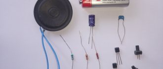
Electrical diagram
You can use a 100 kOhm potentiometer instead of resistor R1 to manually adjust the brightness. 118 Ohm resistors were used as resistance R2.
List of main components that were used:
- R1 - 100 kOhm resistor
- R2 - 118 Ohm resistor
- Transistor bc547
- Photoresistor
- 7 LEDs
- Switch
- Connection to Arduino board
An Arduino board was used as a microcontroller. The power supply from a personal computer was used as power supply. By connecting the multimeter to the red and black cables, you will see 5 volts (which are used for the servo motors and ultrasonic distance sensor). Yellow and black will give you 12 volts (for Arduino). We make 5 connectors for the servomotors, in parallel we connect the positive ones to 5 V, and the negative ones to ground. Same with the distance sensor.
After this, connect the remaining connectors (one from each servo and two from the rangefinder) to the board we soldered and the Arduino. At the same time, do not forget to correctly indicate the pins that you used in the program in the future.
In addition, a power LED indicator was installed on the power board. This is easy to implement. Additionally a 100 ohm resistor was used between 5V and ground.
The 10mm LED on the robot is also connected to the Arduino. A 100 ohm resistor goes from pin 13 to the positive leg of the LED. Negative - to the ground. You can disable it in the program.
For 6 servo motors, 6 connectors are used, since the 2 servo motors below use the same control signal. The corresponding conductors are connected and connected to one pin.
I repeat that the power supply from a personal computer is used as power supply. Or, of course, you can purchase a separate power supply. But taking into account the fact that we have 6 drives, each of which can consume about 2 A, such a powerful power supply will not be cheap.
Please note that the connectors from the servos are connected to the PWM outputs of the Arduino. Near each such pin on the board there is a symbol ~. An ultrasonic distance sensor can be connected to pins 6, 7. An LED can be connected to pin 13 and ground. These are all the pins we need.
Now we can move on to Arduino programming.
Before connecting the board via USB to your computer, make sure you turn off the power. When you test the program, also turn off the power to your robotic arm. If the power is not turned off, the Arduino will receive 5 volts from the usb and 12 volts from the power supply. Accordingly, the power from usb will transfer to the power source and it will “sag” a little.
The wiring diagram shows that potentiometers have been added to control the servos. Potentiometers are optional, but the code above will not work without them. Potentiometers can be connected to pins 0,1,2,3 and 4.