I'm building a model that simulates a real mini jet engine, even if my version is electric. In fact, everything is simple and anyone can build a jet engine with their own hands at home.
The way I designed and built a homemade jet engine is not the best way to do it. I can imagine a million ways and schemes to create a better model, more realistic, more reliable and easier to manufacture. But now I've put together one.
Main parts of model jet engine:
- The DC motor is strong enough and at least 12 volts
- A DC source of at least 12 volts (depending on what kind of DC motor you have).
- A rheostat, the same one sold for adjusting the brightness of light bulbs.
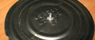
- A gearbox with a flywheel is found in many car toys. It's best if the gear housing is made of metal because plastic can melt at such high speeds.
- A sheet of metal that can be cut to make fan blades.
- Ammeter or voltmeter.
- Potentiometer at approximately 50K.
- Electromagnet coil from a solenoid or any other source.
- 4 diodes.
- 2 or 4 permanent magnets.
- Cardboard to assemble a body similar to a jet engine body.
- Filler for car bodies, to create an exterior.
- Rigid wire to support everything. I usually use wires from cheap hangers. They are strong enough and flexible enough to be molded into the desired shape.
- Glue. I prefer hot glue for most parts, but pretty much any glue will do for now.
- White, silver and black paint.
Run-in after capital
The most enjoyable process in such work is the necessary running-in for the engine with new parts. During break-in, new parts are ground in, so it is not recommended to immediately apply a large load. It is recommended to run-in for up to 2000 km without jerks or sudden starts.
There are several break-in methods:
- Running in cold on a stand.
- Cold running without a stand. This method is common, especially in the CIS countries. After preparing everything necessary (engine oil and coolant are filled in), without starting the engine, tow the car at speed 3 for 2 hours. This method is not recommended. By the way, a very important reminder: motor oil has a code and symbols for additives; before purchasing it, it is advisable to learn how to decipher the markings of motor oils, after which you can make the right choice yourself.
- Hot running. This method involves starting the engine and letting it idle for 3 minutes, then turning off the engine. And they do this several times, only waiting for the engine to cool down. Then, after short starts, start the engine and let it run for 1 hour. During break-in, the engine is inspected for leaks and other indicators. After running in, adjust the valve clearances and set the desired ignition. If contact ignition is installed, it is recommended to install electronic ignition instead of the old one. It reduces fuel consumption and generates high voltage up to 24 kilovolts, while contact ignition can supply no more than 18 kilovolts to the spark plug. Thanks to this, even dirty spark plugs produce a spark.
- Natural run-in. It is run in under the following conditions: smooth ride, speed no more than 60 km. After overhaul without installing new liners, running-in is carried out up to 2 thousand km. If new liners were installed, then 4 thousand km.
Many people recommend breaking in only when cold, but some experts recommend breaking in both cold and hot.
Abroad, they say, car service centers have run-in and test benches for internal combustion engines. Using special electronics, this stand shows the service life of a restored engine.
If you decide not to do the overhaul yourself, but to send it to a service center, you will receive a guarantee for the repaired motor. The guarantee is given depending on how you choose, some for 20 thousand km, others for 30 thousand km. mileage
The procedure for assembling the cylinder head is as follows.
The end of the spiral is secured with a copper wedge in the bolt by striking the beard with a hammer. Mica spacers 0.3 mm thick are placed on the bolt. A bolt is inserted into the head from the hemisphere side. Mica spacers with a total thickness of 0.5 mm are placed in the recess of the head. Then a brass nut is screwed on, which is tightened with round nose pliers until the head is completely sealed. It is necessary to check whether the bolt is isolated from the head. In this case, the sleeve is pressed in, the second end of the glow coil is fixed in place. This is done using a copper wedge. Now you can start checking the serviceability of the glow element. The test is carried out under voltage from one battery bank, giving a voltage of 1.2 - 1.4 V. Several gaskets are made from cold-rolled copper foil of different thicknesses, respectively 0.1, 0.2, 0.3 mm. When tuning the engine, the best one is selected.
The cylinder blank is made from a rod with a diameter of 20 mm (Fig. 2). This workpiece is turned on a machine to a diameter of 18 mm and drilled with a drill with a diameter of 9.5 mm. and then its outer dimensions are machined. When cutting ribs, it is advisable to support the cylinder with the tailstock and cut on the reverse stroke. After this, its internal diameter is machined to a size of 9.8 mm. Cut off from the workpiece, the cylinder undergoes metalworking: the mounting flange is sawed off (you can use an emery wheel), holes are drilled in the head and flange, threads are cut for fastening the cylinder head, exhaust windows are sawn and bypass channels are milled. The cylinder head is heat treated to R 45 - 47. It is advisable to grind the cylinder mirror to a diameter of 10 ± 0.02 mm. The diameter is finally adjusted using a cast iron lap with GOI paste (Fig. 3, b).
Particular attention should be paid to ensuring tightness, for which the upper flange of the cylinder should be ground on the plate. The gasket for the cylinder is cut out of whatman paper (Fig. 2).
The piston is sharpened on a lathe from U10 or U12 steel with a diameter of 12 mm. The workpiece is ground to a diameter of 11 mm and drilled to a diameter of 7 mm, with a depth of 10.5 mm. The piston is bored inside according to the dimensions shown in the drawing. Then the outer dimension is machined to a diameter of 10.2 or 10.3 mm, after which the piston is cut off from the workpiece. After this, a hole for the piston pin is drilled with a drill with a diameter of 2.9 mm and cleaned with a good reamer at low speed, with oil. The piston is calcined to Rc 60-62, ground from the outside to a size of 10 ± 0.02 mm and ground against the cylinder with a cast iron lap (Fig. 3, a). It is also necessary to lap the hole for the piston pin with copper wire 3 mm thick.
The piston pin is made from U8 or U10 steel blank with a diameter of 4 or 5 mm. The workpiece is faced and drilled with a drill with a diameter of 1.9 mm, and then machined from the outside to a diameter of 3.2 mm and cut off from the workpiece. After this, the part should be hardened to Rc = 60-62. Finally, it is ground and ground into the hole in the piston.
The contour of the connecting rod is marked along the rolled product on a pressed duralumin profile D16T. Then two holes are drilled with a drill with a diameter of 2.9 mm at a distance of 18 mm. Metalworking is carried out according to the drawing, after which the holes are turned out using a reamer 3A (with oil), and then cleaned. It is necessary to ensure that no abrasive gets into them, causing severe wear of the piston pin. The surface of the connecting rod is polished with a smooth, hardened steel rod.
For the crankshaft, a blank is machined from steel 12XH3A or 18ХНВА with a diameter of 14 mm and a length of 43 mm. Center recesses are drilled into it: two along the axis of the workpiece and two offset from the axis by 5 mm. First, the crank pin is processed at offset centers, after which the crankshaft journal and toe are machined at the centers on the axle. Then the M4 thread is cut. After this, metalworking is carried out. The part is cemented to a depth of 0.5 mm, heated to Rc - 42-45 and, finally, ground with lapping of the rubbing surfaces.
On a workpiece, clamped into a jaw chuck with a diameter of 50 - 55 mm from D16T, the crankcase toe and crank chamber are machined with threading for the cover, after which the crankcase toe is cut off from the workpiece to the size indicated in the drawing. A bronze bushing, machined in advance according to the drawing, is pressed into the crankcase (Fig. 5). After this, the location of the cylinder is marked and the center recesses are drilled along the axis of the cylinder to process the place of its attachment.
Clamping the crankcase blank in the centers, process a boss with a diameter of 10 mm for gripping with a collet (Fig. 5, d). Clamping the workpiece in the collet, process the cylinder attachment point according to the drawing.
Then the crankcase is milled and machined. The rear crankcase cover (Fig. 5) with the carburetor is machined from the D16T workpiece in two steps. First, trimming is done, then processing according to external dimensions and cutting the hole for the axle. At a length of 18 mm, the cover is cut off from the workpiece and the carburetor hole is marked, which is drilled with a drill with a diameter of 3.9 mm and cut with a 4A3 reamer. The part is clamped in the center, and the carburetor body is turned. After this, metalworking of the part takes place according to the drawing (Fig. 3).
The jet and needle nut are machined from L59 or L62 brass according to the drawing (Fig. 3).
The carburetor needle is made on a lathe from OBC wire, previously normalized (heated to 200 - 240 ° C for 20 - 30 minutes). The thrust washer and spinner (Fig. 3) are machined from D16T according to the drawing. The mounting screws are selected according to the location and diameters indicated in the drawings. The dimensions and materials of gaskets and washers are indicated in the drawings.
The axle is made of OVS wire with a diameter of 2.5 mm and ground to the drawing dimensions.
The spool washer (Fig. 3) is made from 1.5 mm textolite or getinax. A round workpiece is turned on a lathe, then it is machined to the size of the frames indicated in the drawing, and the working surface is ground in.
Engine assembly
The engine is assembled in the following sequence:
- 1) the spool axis is pressed in;
- 2) put on a spool lubricated with oil;
- 3) the crankshaft, lubricated with oil, is inserted into the crankcase;
- 4) the connecting rod is connected to the piston by a piston pin, the lower head is put on the crankshaft crank pin;
- 5) the cover with gasket and spool is screwed into the crankcase;
- 6) a gasket is placed under the cylinder, the piston and cylinder are lubricated with oil, the cylinder is put on the piston;
- 7) tighten M2 mounting screws 5 mm long;
 check the ease of rotation of the crankshaft;
- 9) put on the thrust gasket, thrust washer, screw and spinner, again check the ease of rotation of the crankshaft;
- 10) install the jet and nut with a needle on the carburetor;
- 11) the head with gaskets is put in place, and the engine is installed on the stand; the fuel tank is connected with a rubber tube;
- 12) having connected the battery to ground and the cylinder head nut, turn the engine shaft by the screw; Having closed the carburetor with your finger, try to start the engine by sharply pressing the screw with your index finger.
A cadmium-nickel battery is used, brand KN-10 - 2 banks of 2.4 V.
The speed is adjusted using the carburetor needle. As soon as the engine mode becomes stable, disconnect the wires from the motor. It is necessary to run in the engine for 30-35 minutes before operation.
E. SUKHOV, V. NOSKOV
for the magazine Modelist Constructor
You may be interested in looking at other articles about the modification of aircraft model engines
How to make “Veterok”?
The manufacture of the engine must begin with the most important part - the cylinder. The cylinder consists of a head, bushing, bolt, mica spacers, glow thread, nut and wedges.
The head itself is made of D16T material with a diameter of 20 mm. The bar is clamped into the jaw chuck, and complete processing is carried out according to the drawing of the side of the bar where the spherical recess should be. Next, holes with a diameter of 4 and 22 mm are drilled. The spherical recess is polished with GOI paste. The part is then cut from the workpiece. The reverse side of the part is processed in a special mandrel, which is clamped into the jaw chuck of the machine. Then holes are marked and drilled for the screws attaching to the cylinder.
The bolt is sharpened from U5 steel according to the drawing. A blind hole with a diameter of 0.6 mm is drilled in the head of the bolt for a copper wedge for embedding the glow thread.
This hole is drilled at an angle to the body of the bolt. The nut and bushing are sharpened from brass and duralumin D16T, respectively, according to the drawing.
Glow filaments can be made from platinum, rhodium or iridium wire. It is possible to use wire from old thermocouples of heating thermal furnaces, and they must be calibrated with dies.
The die is a plate of cold-worked stainless steel (or U8 steel) 0.3 mm thick. In this plate you need to punch a hole with a broken needle using a hammer. Hold the needle with pliers. Pulling the wire for the thread is shown in Figure 3c.
The thread is wound into a spiral on a mandrel with a diameter of 1 mm. The winding pitch is 0.6-0.7 mm.
Spirals twisted from double or triple platinum wire 0.05 mm thick work especially well.
Do-it-yourself rubber-powered airplane
I recently found a reel with a rubber band for fishing (for casting the so-called donkey) and, as usual, figured out how it could be used in aircraft modeling. Two ideas came to mind:
1) Attach the wing 2) Rubber motor
The second idea interested me more than the first. Why not try building a model with a rubber motor? Yes, there was also a competition for articles... Unfortunately, or maybe fortunately, I don’t know any calculation formulas, and I don’t need it yet - in a word, I built it by intuition.
Looking ahead, I will say that the model was not a success =( Either it turned out to be too heavy, or a special rubber band was needed, but the rubber motor did not work. The model looked kind of scanty, unfinished.
However, the plane was planning, and this forced me to still participate at my own peril and shame in the competition.
I wrote the article on making the model even before the first tests, so I didn’t yet know about my failure =)
What will you need? — A sheet of ceiling paper (I lost a sheet somewhere) — A wooden ruler (consumables) — An iron ruler — A sharp knife (the ability to wield it) — The same rubber band (preferably stronger and longer) — Several paper clips — Possibly a drill — Air screw (preferably small in size with large increments) - Thin marker or gel pen - Printer for printing drawings - Possibly a clothespin - Thin aluminum plate (can be done without it or with any material with a smooth surface) - Small pliers (bend paper clips) - A couple of toothpicks - Titan glue or an analogue - Perhaps 5-minute epoxy or other epoxy resin My ceiling was 4 mm thick, so all the drawings, etc. were designed for exactly this thickness of the ceiling. Let's begin.
This is what happened when I first drew the fuselage =)) Funny =) There’s no need to laugh, it will be better later: Hmm... Not very good, but oh well. This is what happened after cutting: By the way, the ceiling has one feature: it bends in one direction better than in the other. This depends on the direction of the fibers of the sheets. The fuselage should be positioned PARALLEL to the grain, i.e. It should bend worse in length than in width. The same applies to the wing and, in general, all ceiling models. Kiel turned out to be simply terrible, but oh well. It is important for us to maintain the width of the fuselage throughout its entire length, so that the elastic does not fold it in half. Two stripes in the middle are where the slot for the elastic is. Next, we cut out exactly the same half of the fuselage. There is one important point here. The second part must be cut so that it is a mirror image of the first part. Let me explain. It may be that your ceiling is not perfectly level. Then one half will look like this: We need to make sure that when gluing the second part is bent in the opposite direction - this will strengthen the structure and the fuselage will be even. This is what it should look like: But I glued these halves in reverse (not like in the photo above: I glued the top half to the bottom). Pour a little glue onto one side, spread it with a toothpick, leaving a THIN layer of glue. We wait a couple of minutes and stick the other half. It is unlikely that you will be able to cut and glue everything perfectly, so after the glue has set, we take a sharp knife and trace our fuselage along the edge. IMPORTANT: Keep the knife at right angles to the fuselage surface. This is what is left of my fuse =) Previous — Next >>
Do-it-yourself rubber-powered airplane
Do-it-yourself rubber-powered airplane
Attention, today we have another exclusive! Kids, stop what you’re doing, and parents, quickly provide your child with the necessary engineering equipment and consumables. Carlson is resting. Now we will make a rubber-powered glider from sushi sticks.
And no matter how ridiculous it may sound, he will fly! Remembering my childhood, I can only add one thing. It was much more interesting than getting a ready-made toy from the store. No matter how cool it is. Of course, we will need not only sushi chopsticks, or rather, just one stick.
First, let's list in detail everything you need:
In addition to all of the above, you may need a kettle and chewing gum. And, by the way, the ice cream stick should be approximately the same shape as in the picture (they exist – I’ve seen them). In fact, we don’t need a handle. A rod will be needed, and it must be empty.
As you can see, you need to cut out a wing, a tail and two stabilizers from cardboard. This is what we will do first. The shape will be clear to you from the drawing, but try to estimate the dimensions yourself. Start from the length of the sushi stick. Plus, the width of the stabilizers should be equal to the width of the tail (at least approximately).
Now we glue the tail and wing to the sushi stick - our fuselage. In the picture above you can see that the nose of the glider is the wide part of the stick. Be sure to wait for the glue to dry before continuing.
SECRETS OF RUBBER MOTOR
For many years, the rubber motor, due to its ease of operation and low cost, was the main engine for modellers. However, even now, with the abundance of micromotors, ship models and car models with rubber motors find their ardent supporters, as evidenced, in particular, by the editorial mail. Among your questions, dear readers, two are most common. Thus, T. Zavgorodniy from Volgograd, E. Shcherbina from Semipalatinsk, A. Zhdanov from Moscow and others are interested in how to calculate the number of revolutions of a rubber motor in order to make the most of its energy, and also what is associated with its maximum energy output.
The rubber motor operates using the internal energy of stretched rubber threads. They can increase their length quite significantly: 6-7 times or more, and different varieties stretch differently. There are several formulas that modelers can use when calculating a rubber motor. Using one of them, you can determine the relative elongation λ (lambda) - the ratio of the increment in length to the original. This is written as a formula:
where 1 is the length of the rubber in the free state, and Δ1 is the increment in length.
When stretching a rubber thread, we expend a certain energy, but we get back only 65-67%. The loss is caused by the costs of internal friction in the rubber itself. Consequently, the coefficient of performance (efficiency) of a rubber motor cannot be more than 0.65-0.67.
To accumulate more energy in a rubber motor, you need to increase its twist while maintaining the mass of rubber. Moreover, the thicker the rubber motor, the smaller it will be. This contradiction is solved by composing a rubber motor from several separate threads. Since when the rubber motor spins up, the loss of power is caused by both internal friction and friction between individual threads, the practical number of revolutions is always less than what should be obtained according to calculations. We propose an approximate formula for calculating the number of revolutions:
here: N is the maximum winding of the rubber motor in revolutions,
E is the initial length of the rubber motor in centimeters,
λ - maximum relative elongation according to rubber characteristics or obtained experimentally,
K is some experimental coefficient.
It should be said that the accuracy of the calculation using this formula will increase if the rubber motor is first stretched before the factory. Experiments have shown that with increasing pre-stretch, the number of revolutions increases, which is taken into account by introducing the experimental coefficient K into formula 2. This effect on the plant is apparently explained by the fact that the distribution of friction between the fibers, and especially between the threads of the rubber motor, changes.
The values of the experimental coefficient K depending on the preliminary drawing are given in the table.
To reduce friction between the strips, the rubber motor is usually lubricated with castor oil or glycerin (this also increases its durability). If we take the useful energy of the rubber motor as 100%, then when twisting without preliminary stretching we will lose 30-35% to friction, and by lubricating it and applying preliminary stretching 1 to 3 times, we can reduce the losses to 5%.
Source