How to make an antenna for a walkie-talkie
If you are the owner of a walkie-talkie, then it will be no secret to you that homemade antennas for these devices are more effective than factory ones. The size of the homemade product, by the way, can be set within 9-25 cm. You will need:
- connector suitable for your walkie-talkie;
- a piece of any thick cable (only insulation is needed from it);
- PEV wire 0.25-0.7 mm;
- heat shrink;
- glue.
The manufacturing process looks like this:
- Pull all contents out of the cable without damaging the outer tube of insulating material.
- At this stage, check how well this tube fits into the connector - ideally it should fit into it.
- On the tube, 4-5 mm away from the level of the connector, you need to make a hole for the wire, where the latter should be placed - inside the pipe.
- Solder the central pin of the connector to the end of the wire, and then glue the tube into the last one.
- The PEV wire protruding from the tube should be wound in equal turns from the connector outward. The winding length is 10-25 cm. The thicker the cable, the longer the winding.
- Secure the skeins with glue to prevent them from unwinding.
- Test the device and trim the winding if necessary.
The result of the alteration: I was looking for a handset and found an open door
In Fig.
Figure 1 shows the appearance of the Texet TX-D5300 wireless kit: base and one handset.
To modify the standard kit (base + tube), you will need to take a few simple steps. Here they are:
- disassemble the base of the radiotelephone (remove the housing to access the printed circuit board);
- connect a two-wire cable with a maximum length of no more than 1.5 m parallel to the contacts of the “tube search” button (to avoid false positives from AC voltage pickups from network wires);
- connect the other end of the cable to a limit switch (for closing) or a reed switch for opening (with a normally closed group of contacts) installed on the front door frame (see details below);
- install (fix) the radiotelephone base here, not far from the “remote switch”;
- using a standard adapter, connect the base to a voltage of 220 V;
- connect the remote handset to another (additional) network adapter with an output voltage of 3-5 V, so as not to depend on the discharge of batteries or batteries in the handset;
- install the handset with the adapter in the desired place, for example, not far from the desktop.
Let's look at these steps in more detail.
In Fig. Figure 2 shows a view of the base with the housing cover removed.
In the center of the printed circuit board (Fig. 2) there is a button with short-circuit contacts; it has 4 pins, two of which are connected (duplicate each other). Using an ohmmeter, we check the connection in the contact group of the button - when you press it, we identify the closing contacts.
In parallel, with a soldering iron with a thin tip and a power of up to 25 W (so as not to damage the radio elements on the printed circuit board), we solder a two-wire cable; there is no need for its shielding (Fig. 3).
The connection diagram is quite simple, and, in my opinion, does not even need to publish a separate drawing. This is a reed switch connected parallel to the “tube search” button (on the base).
The base has nothing to do with it: the trill will sound in 3 seconds
When you press the “handset search” button (in the central part of the base) - provided that the base is connected to a 220 V network and the batteries are charged directly in the handset - the latter emits a short trill lasting 2.5...3 seconds. Moreover, this happens regardless of whether a telephone line is connected to the base, which made it possible to use the old radiotelephone for other purposes.
If you press the “tube search” button for a long time (or repeated many times with a frequency of more than 1 time in 5 seconds), the sound signal will still only sound once, lasting a few seconds. The same will happen when opening a door on which a “contact closure” is installed. This is a feature of the industrial development of the Texet TX-D5300 phone.
In Fig. Figure 4 shows a reed switch combined with a magnet on the moving part of the door.
When the door is tightly closed (Fig. 4), the magnet acts with its field on the reed switch and the contacts of the latter open. When the door is opened, the reed switch is in normal mode with the contacts closed. This condition is transmitted to the base and the telephone handset emits a heart-rending beep. As a reed switch I use KEM-3-1 with three contacts.
To power a radiotelephone handset located within 30 meters from the base, I use an adapter for powering a Nokia cell phone with a constant output voltage of 3.7...4.2 V. In this case, any unnecessary charger with an output voltage in the specified range will do.
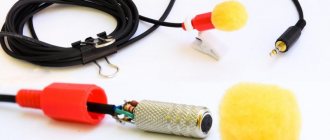
Rice. 5. Radio tube and new power adapter
Technical characteristics of the Texet TX-D5300 base unit
- DECT GAP standard (possibility of registering additional handsets from other manufacturers);
- menu in Russian;
- phone book for 50 names and numbers (repeat the last 10 dialed numbers);
- Caller number identification (Caller ID) with memory of 40 numbers
- ability to connect up to 5 handsets (wireless PBX): internal connection between handsets;
- operating frequency: 1880-1900 MHz;
- range of the Texet TX-D5300 wireless kit indoors/outdoors up to: 50 m/300 m;
- Caller ID only in the Texet TX-D5300 Black model;
- interfaces: Texet TX-D5300 Black RJ-11 input.
Security and service functions in the Texet TX-D5300 Black model:
- mute the microphone;
- Keypad lock;
- time indication;
- low battery indication;
- indication of leaving the communication zone of the base unit;
- search for handset.
The base is powered by a 6.5 V DC power adapter (current consumption 150 mA).
The phone is powered by two AA size AA batteries with a voltage of 1.2 V and an energy capacity of 550 mAh each.
How to make an antenna for a walkie-talkie
If you are the owner of a walkie-talkie, then it will be no secret to you that homemade antennas for these devices are more effective than factory ones. The size of the homemade product, by the way, can be set within 9-25 cm. You will need:
- connector suitable for your walkie-talkie;
- a piece of any thick cable (only insulation is needed from it);
- PEV wire 0.25-0.7 mm;
- heat shrink;
- glue.
The manufacturing process looks like this:
- Pull all contents out of the cable without damaging the outer tube of insulating material.
- At this stage, check how well this tube fits into the connector - ideally it should fit into it.
- On the tube, 4-5 mm away from the level of the connector, you need to make a hole for the wire, where the latter should be placed - inside the pipe.
- Solder the central pin of the connector to the end of the wire, and then glue the tube into the last one.
- The PEV wire protruding from the tube should be wound in equal turns from the connector outward. The winding length is 10-25 cm. The thicker the cable, the longer the winding.
- Secure the skeins with glue to prevent them from unwinding.
- Test the device and trim the winding if necessary.
Zello-walkie-talkie application
The most convenient and easiest way to experience the beauty of talking on a walkie-talkie is to install an application with this function on your smartphone. The leader among them is Zello, which can also be installed on a laptop or PC. The program is completely free for all existing operating systems. Zello is often used by mobile software developers - it allows them to add the function of communicating via walkie-talkie to their applications.
Zello uses Wi-Fi or mobile Internet to transmit voice. The application also supports Bluetooth headset. Your voice message is first saved by the system and then sent to the recipient. Zello supports communication between 800 interlocutors, displays their connection status, stores voice message histories, and creates special password-protected channels.
DIY stereo transmitter circuit diagram
The scheme is simple, especially if you understand its operation. I suggest you immediately visually divide it into the left side with one transistor and the right side with two transistors. The transistor VT1 assembles a transmitter and a receiver at the same time. When the switch closes contacts “1”, the radio is in receive mode and this transistor operates in supergenerative detector mode. And when the contacts close to mode “2”, this is transmission and the transistor works as a master oscillator. With this, I think it’s clear. A simple low-frequency amplifier is assembled on transistor VT2, VT3, which, depending on the position of the switch, either amplifies the signal from the microphone and transmits it to the transmitter, or amplifies the signal from the supergenerative detector and transmits it to the loudspeaker. By the way, the loudspeaker and microphone are one and the same element - a high-impedance DEM telephone capsule. Coil L1 is wound on a frame with a diameter of 8 mm with a ferrite core turn to turn and has 9 turns of PEL wire with a diameter of 0.5 mm. Coil L2 is wound on top of coil L1 and has 3 turns of the same wire. Coil L3 has a diameter of 5 mm and contains 60 turns of PEL wire with a diameter of 0.5 mm. As an inductor L4, you can use the primary winding of the output transformer of a transistor receiver. The antenna was made by me from a thick aluminum wire, with a piece of insulation, on top of which the L3 coil was wound. I made such a walkie-talkie back in school, but then I already changed all the transistors to more modern ones with high gain. For example, I replaced VT1, VT2 with KT361, and VT3 with KT315. Now I would, of course, change the power polarity and the polarity of the capacitors, replace all transistors from the npn structure to pnp, and pnp to npn. Well, I would install modern transistors. There are no particular requirements for transistors, so absolutely any will do. The author of the diagram says that the range of action of radiums of the same type in open areas is 100-200 meters. I accelerated such radios to 500 meters, for this I used modern transistors, increased the antenna to 900 mm, plus increased the generator current by replacing the 100 Ohm resistor with a 50 Ohm one. Someone will say that it’s all due to the enlargement of the antenna, with which I disagree and will say that with the “native” antenna I was able to communicate over 300 meters. If you assembled the walkie-talkie correctly and from serviceable parts, then the whole setup will come down to tuning coil L1 at a frequency of 27 MHz. This can be done with a subline core or a capacitor in the circuit.
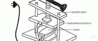
Manufacturing process
First you need to make a U-shaped chassis from aluminum sheet. Controls will need to be placed on it. In this case, the power supply should be taken ready-made from a radio, radio or TV. It should give a constant anode voltage of 150-250V, as well as a filament voltage of 6.3V. Then, in accordance with the transceiver circuit, you need to assemble the walkie-talkie:
The transceiver circuit coil must be made of copper wire with a diameter of 1 mm. You need to take a bare wire, or even better, a silver-plated one. It should be wound on a rod having a diameter of 12 mm. The coil should contain 4 turns with a tap in the middle. In this case, the communication coil with the antenna is located on top of the circuit coil and contains 1-2 turns of the same wire. The chokes should be wound around resistance BC-0.25. They must contain 0.5 m of PEL-0.15 wire.
As for the tuning capacitor C, it can be taken with a ceramic dielectric, however, it is better if it has an air dielectric with one movable plate or with two fixed plates. Transformer Tr1 should be taken from a TV or tube receiver. It should be noted that the high-resistance winding of the same transformer is used as a choke Dr6. If you are thinking about how to make a walkie-talkie from a telephone, and decide to use low-impedance telephone speakers, then you need to include them in the low-impedance winding of this transformer. You should also note that if you want to use a telephone in the circuit, it cannot be used as a walkie-talkie. But it’s worth taking a carbon microphone from it. Biscuit switches are well suited as a “Receive-Transmit” switch.
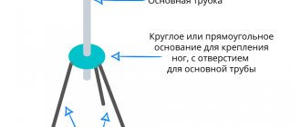
Antenna
The next stage is creating and configuring the antenna. Let's look at how to make an antenna for a walkie-talkie. So, after the radio body is assembled, you will need to make exactly 11 turns of wire with a thickness of 0.5 mm for the L1 coil. This uses a range setting of 27-30 MHz. If precise adjustment of the range is needed, then it is necessary to use tuning capacitors C1 when receiving data, as well as C2 when transmitting data. In addition, the reception mode of switch SA1 should be taken into account. The range should be adjusted using a factory-made control receiver. You can simplify this task by taking out your headphones, so the setup will be much faster.
How to solder a radio station on the 50 MHz range with your own hands
Just a warning. If you want to build a cheap walkie-talkie not for study or experimentation, then you have come to the wrong place. Buy this LPD
or a couple of these
walkie-talkies
, because then you won’t be interested.
When assembling a radio station, you must have experience in soldering components, skills in determining the ratings of components and installing them on printed circuit boards by soldering. The tool for the job is a low-power soldering iron with solder and rosin, wire cutters and a Phillips screwdriver.
The basis of the designer is a set of radio components JC986A, which includes all the necessary components (except for a 9V battery) for assembling one walkie-talkie in the operating range of radiotelephones (frequencies around 49.8 MHz). In total, you need to collect at least two walkie-talkies. All details of the designer are shown in the photo. The body is made of good quality, but not made of impact-resistant polystyrene. All plastic elements fell into place without problems. The board withstood all soldering and elimination of installation errors, the tracks did not peel off. All tracks are coated with flux, soldering was carried out without problems. The parts were complete.
Kit (in polyethylene) Kit parts Housing and plastic parts Parts list Printed circuit board Parts side printed circuit board Walkie-talkie speaker Radio circuit
Circuit diagram of a simple radio station
A diagram of the walkie-talkie is attached and it is printed in Chinese style, as are their characters. The meaning of the circuit's operation is hidden in the circuit diagram. The author has redrawn the diagram for a better understanding of its operation. See photo.
The radio is controlled by two switches. The non-fixed switch S1 switches the reception-transmission mode of the radio station (in the diagram the switch is in the reception mode). Switch S2 supplies power to the radio. Transistor Q1 operates as a super-regenerative receiver. The RF signal to the receiver is supplied from the Ant antenna and the L1 coil to the C1T1C4 circuit. The reception frequency is mainly determined by this circuit. The resonance frequency of the circuit can be changed using a tuning core. When switch S1 is switched to transmit mode, the receiver circuit switches to RF oscillation generator mode at the receiving frequency. A transformerless low-frequency amplifier is assembled using transistors Q2-Q5. In the LF reception mode, the receiver signal through the chain R5, C10, C14 is supplied to the ULF input and is amplified. The ULF load will be the SP speaker. In transmit mode, the speaker is connected by switch S1 to capacitor C14 (it becomes a microphone) and the ULF amplifies the signal from the speaker. The ULF load becomes an HF generator to which an alternating voltage is supplied from the midpoint of the ULF amplifier through the limiting resistor R9. The AC voltage modulates the RF output signal to the antenna. The antenna is connected through an extension coil - inductor L1. The board provides space for three more elements of a tone call during transmission - R10, C7 and a button (these parts are not included in the kit).
Step-by-step instructions for assembling a radio station with your own hands
Step 1. After receiving the parcel, check the completeness of the body parts and radio components. Study the labeling. Resistor values are color coded. The reading key is attached on the page. Do not confuse inductor L1 with resistors, it is much larger. Small parts are best stored in a closed box. Study the printed circuit board from the parts side to understand where to mount the parts.
Board with installation drawing Key to resistor code
Step 2. We begin soldering by installing resistors. We form the resistor electrodes. We solder it onto the board and cut off the protruding electrodes with wire cutters. This is how we install all the elements with long electrodes. The location of each element is marked on the board. Be careful - don't make mistakes. Solder all resistors in series. See photo.
Step 3. Solder the extension coil L1. See photo.
Step 4. Solder the capacitors. See photo.
Resistors are soldered Capacitors are soldered
Step 5. Solder the electrolytic capacitors. The elements have installation polarity. The correct installation of the negative electrode is shown in the photo.
Step 6. Solder the contour coil T1, switch S1. The metal body of the switch must be soldered to the board.
Correct installation on the board Installing switch S1
Step 7. Solder the transistors, strictly adhering to the markings on the board. The position of the housing of each specific transistor on the board is shown in the figure.
Step 8. From pieces of cut electrodes, solder jumper J1 onto the board. See photo.
Assembled board
Step 9. Check the correctness and quality of installation of the elements. You can wash the board from flux residues with alcohol. We install a plastic switch button for receiving and transmitting. We fasten the board to the case with two self-tapping screws.
Step 10. Install the antenna. We install a plastic cap on top of the antenna. We solder the connection conductor to the board to the antenna lobe. We solder the switch S2 with pieces of conductors from the parts. Checking the operation of the power switch. The shift lever should move when the plastic knob is rotated.
Installation and connection S2
Step 11. Tin the places where the wires are soldered to the battery compartment terminals. Install the terminals into the battery compartment. We solder the speaker connection conductors and the power supply conductors from the battery compartment. Observe polarity! You can insert the battery and, if you are sure that everything is assembled correctly, apply power. The hiss of the receiver should be heard from the speaker. The operation of the transmitter can be assessed using a field indicator. We connect the two halves of the case with five self-tapping screws. Watch the video.
Transmission check
Step 10. Similarly, we assemble the second radio station. For proper operation, the receiving and transmitting frequencies of each radio station must be the same. To do this, the board of one radio station is removed from the fastener. An improvised dielectric screwdriver with a straight slot is made from a match. We turn on one radio station for reception, the second disassembled for transmission (the distance between the stations is 1 meter) and by rotating the circuit core with a wooden screwdriver we achieve a loud voice when receiving the first radio station.
Checking the RDS settings of the receiver
We repeat these operations at a distance of 5 and 20 meters. Setting up is best done outdoors. Do not forget, the radio stations are simple and the signal will be affected by objects located directly close to the antenna and the signal capture by the receiver may not work. It is very convenient to use the SDR USB receiver when setting up. Watch the video. It will allow you to evaluate signal strength, frequency, frequency stability and modulation quality. We assemble the housing of the second radio station.
At this point, setting up radio stations in such a circuit design can be completed. The communication range between radio stations in open areas is about 100 meters. But this is not the limit; with appropriate modifications or simply connecting the appropriate antennas, the communication range can easily reach several kilometers. If there is interest in the topic, the author will publish some of the improvements. The station is interesting for its range and amplitude modulation. Others interfering in your conversations is possible, but unlikely. The radiated power at the radio station's antenna is less than the limits requiring permitting or registration.
This circuit of a shortwave radio station contains only three transistors. The simplest walkie talkie for beginner radio amateurs. The design was taken from an old magazine, but it has not lost a bit of its relevance. The only thing that is outdated is the radio components, which need to be replaced with modern analogues, as a result the characteristics of the radio intercom will improve.
How to assemble a simple radio receiver?
There are several radio receiver circuits:
- detector;
- direct amplification;
- (super) heterodyne;
- on a frequency synthesizer.
Receivers with double and triple conversion (2 or 3 local oscillators in a circuit) are used for professional work at the maximum permissible, ultra-long distances.
The downside of the detector receiver is low selectivity: signals from several radio stations can be heard simultaneously. The advantage is that there is no separate power supply: the energy of the incoming radio waves is enough to listen to the air without powering the entire circuit. At least one repeater must be broadcasting in your area - in the range of long (148-375 kilohertz) or medium (530-1710 kHz) frequencies. When you are 300 km or more away from it, you are unlikely to hear anything. It should be quiet around - it is better to listen to the program using headphones with high (hundreds and thousands of ohms) impedance. The sound will be barely audible, but both speech and music will be understandable.
The detector receiver is assembled as follows. The oscillating circuit consists of a variable capacitor and a coil. One end of it is connected to an external antenna. Grounding is supplied through the building circuit, and the heating network pipes are supplied to the other end of the circuit. Any RF diode is connected in series with the circuit - it will isolate the audio component from the RF signal. A capacitor is connected to the resulting assembly in parallel - it will smooth out the ripples. To extract sound information, a capsule is used - the resistance of its winding is at least 600 Ohms.
If you disconnect the earphone from the DP and send a signal to a simple audio amplifier, then the detector receiver will become a direct amplification receiver. By connecting a MF or LW radio frequency amplifier to the input - to the circuit - you will increase the sensitivity. You can move up to 1000 km from the AM repeater. A receiver with a simple diode detector does not work on the (U) HF band.
To improve adjacent channel selectivity, replace the detector diode with a more efficient circuit.
To ensure selectivity in the adjacent channel, a local oscillator, a mixer and an additional amplifier are needed. A local oscillator is a local oscillator with a variable circuit. The heterodyne receiver circuit works as follows.
- The signal comes from the antenna to a radio frequency amplifier (RFA).
- The amplified RF signal passes through a mixer. The local oscillator signal is superimposed on it. A mixer is a frequency subtractor: the local oscillator value is subtracted from the input signal value. For example, to receive a station on 106.2 MHz in the FM band, the local oscillator frequency must be 95.5 MHz (10.7 remains for further processing). The value 10.7 is constant - the mixer and local oscillator are adjusted synchronously. Mismatch of this functional unit will immediately lead to the inoperability of the entire circuit.
- The resulting intermediate frequency (IF) of 10.7 MHz enters the IF unit. The amplifier itself performs the function of a selector: its bandpass filter cuts the spectrum of the radio signal to a band of only 50-100 kHz. This ensures selectivity on the adjacent channel: in the densely packed FM range of a large city, radio stations are located every 300-500 kHz.
- Amplified IF is a signal that is ready to be transferred from the radio frequency region to the audio frequency region. The amplitude detector converts the AM signal into audio, highlighting the low-frequency envelope of the radio signal.
- The resulting sound signal is sent to a low-frequency amplifier (LF) - and then to a speaker (or headphones).
The advantage of the (super) heterodyne receiver circuit is satisfactory sensitivity. You can move tens of kilometers away from the FM transmitter. Selectivity on the adjacent channel will allow you to listen to the radio station you like, and not to the simultaneous cacophony of several radio broadcasts. The disadvantage is that the entire circuit requires power - several volts and up to tens of milliamps of DC.
There is also selectivity along the mirror channel. For AM receivers (LW, MW, HF bands) the IF is 465 kHz. If in the CB range the receiver is tuned to a frequency of 1551 kHz, then it will “catch” the same frequency at 621 kHz. The mirror frequency is equal to twice the IF value subtracted from the transmitter frequency. For FM (FM) receivers operating in the VHF band (66-108 MHz), the IF is 10.7 MHz.
Thus, a signal from an aviation radio (“mosquito”) operating at 121.5 megahertz will be received when the receiver is tuned to 100.1 MHz (minus 21.4 MHz). To eliminate the reception of interference in the form of a “mirror” frequency, an input circuit is connected between the RF amplifier and the antenna - one or more oscillating circuits (a coil and a capacitor connected in parallel). The disadvantage of a multi-circuit input circuit is a decrease in sensitivity, and with it the reception range, which requires connecting an antenna with an additional amplifier.
The FM receiver is equipped with a special cascade that converts FM into AM waves.
The disadvantage of heterodyne receivers is that the signal from the local oscillator without an input circuit and in the presence of RF feedback enters the antenna and is re-radiated into the air. If you turn on two such receivers, tune them to the same radio station, and place them side by side, close together, a slight whistling of a changing tone will appear in the speakers of both. In a circuit based on a frequency synthesizer, a local oscillator is not used.
In FM stereo receivers, after the amplifier and detector, there is a stereo decoder. Stereo signal encoding at the transmitter and decoding at the receiver is carried out using pilot-tone technology. After the stereo decoder, a stereo amplifier and two speakers are installed (one for each channel).
Receivers that do not have stereo decoding function receive stereo broadcasts in monaural mode.
To assemble the receiver electronics, do the following.
- Drill holes in the workpiece for the radio board, checking the drawings (topology, arrangement of elements).
- Place radio elements.
- Wind the loop coils and magnetic antenna. Place them according to the diagram.
- Draw the tracks on the board, checking the topology from the drawing. Paths are made both by cutting and etching.
- Solder the parts onto the board. Check the correct installation.
- Solder wires to the antenna input, power supply and speaker output.
- Install controls and switches. A multi-range model will require a multi-position switch.
- Connect the speaker and antenna. Turn on the power supply.
- The noise of an untuned receiver will appear in the speaker. Turn the tuning knob. Tune to one of the available stations. The sound of the radio signal should be free of wheezing and noise. Connect an external antenna. You need to adjust the coils and shift the range. Choke coils are adjusted by rotating the core, frameless coils are adjusted by stretching and compressing the turns. They require a dielectric screwdriver.
- Select an extreme frequency on the FM modulator (for example, 108 MHz) and move the turns of the local dyne coil (it is located next to the variable capacitor) so that the upper end of the receiver range stably receives the modulator signal.
Assemble the body:
- Mark and cut plywood or plastic into 6 edges of the future body.
- Mark and drill holes for the corners.
- Cut out a large round gap for the speaker.
- From the top and/or side, cut out slots for the volume control, power switch, band switch, antenna and frequency control knob, guided by the assembly drawing.
- Install the radio board on one of the walls using “pile” type screw racks. Align the controls with the technological holes on the adjacent sides of the housing.
- Mount the power supply - or USB board with lithium-ion battery (for the mini radio) - away from the main board.
- Connect the radio board to the power supply board (or to the USB controller and battery).
- Connect and secure the magnetic antenna for AM and the telescopic antenna for FM. Securely insulate all wire connections.
- If a loudspeaker model is being manufactured, install the speaker on the front edge of the case.
- Using the corners, connect all the edges of the body to each other.
For the scale, calibrate the adjustment knob and place a mark in the form of an arrow next to it on the body. Install an LED for illumination.
8 photos
Recommendations for Beginners
- To avoid overheating diodes, transistors and microcircuits, do not use a soldering iron with a power of more than 30 watts without flux.
- Do not expose the receiver to precipitation, fog, frost, or acid fumes.
- Do not touch the high voltage terminals of the power supply when the device under test is energized.
Algorithm for creating a 50 MHz walkie-talkie
If you purchased a ready-made kit for creating a walkie-talkie with your own hands, you will need the following diagram. The names of the elements must be indicated on your board and diagram attached to the device for making a simple walkie-talkie.
First, start installing resistors and forming the electrodes of this element. Using a soldering iron, the resistor must be soldered to the board, and the protruding electrodes must be cut off with wire cutters. Carefully and carefully install all components, relying on the drawn outline on the board.
Start soldering the extension coil L 1, and then the capacitors. The next step is to solder the electrolytic capacitors. Since they have a certain polarity, it is necessary to properly fit the negative electrode into the board.
Using a soldering iron, attach the contour coil T 1 and the body of the switching element S 1. Proceed to soldering the transistors, relying on the contour drawn on the board. You need to solder the cut parts of the electrodes remaining from step 1 to the board. Do this so that jumpers J 1 are formed.
Now you can check the quality of the work performed. If necessary, wipe the board with an alcohol solution, and later install the on/off button. Attach the finished board to the case using self-tapping screws.
Now you can install one of the main elements of the walkie-talkie - the antenna. On top of it there should be a small plastic cap, on the other side you need to solder a conductor that will connect the antenna to the board. Using the remaining pieces from the conductors, attach the S 2 switch to the board and check its functionality.
Place the terminals in the battery compartment. Now you need to solder the conductors responsible for the speaker and power supply system. If you have no doubt that you did everything correctly, connect a battery to the mechanism and check it. The finished device should make a hissing sound.
Assemble the second radio in the same way as the first. To ensure that the devices operate with the same cleanliness, remove one board from the fastener. We hope that these detailed instructions for creating a walkie-talkie with your own hands helped you understand the creation of this mechanism.
iPTT - walkie-talkie for iOS
Even a small child can figure out how to make a walkie-talkie on an iPhone or iPad using this application - it’s so easy to use. By the way, iPTT is the first application of its kind in the AppStore, and it’s completely free.
Using this program, you can create a direct communication channel with both an individual recipient and a group of people. You can also select the “whisper” mode - confidentially communicate with one person from the group.
An application similar in functionality to iPTT will be TiKL Touch Talk Walkie Talkie. It is available for free not only for gadgets on iOS, but also on Android.
Settings
If you assembled the radio correctly and from serviceable parts, then the entire setup will come down to setting the L1 coil to a frequency of 27 MHz. This can be done with a subline core or a capacitor in the circuit. One of the most popular amateur radio designs is the pocket radio. Of course, in our era of the total proliferation of mobile phones and pagers, the manufacture of homemade communication equipment has lost its relevance. However, in some cases, an FM radio may be indispensable, since it works regardless of the coverage of cellular stations. And the money in the account tends to run out at the most inopportune moment - for example, when listening to a room for a long time. This is where our simple, proven FM radio, based on a 4-transistor transmitter and receiver at a frequency of 100-105 MHz, comes in handy. Recently this design was published on our friendly website, but now we present the circuits in good quality, translated into Lay format by our respected comrade Alex1. The figures below show a diagram of the receiving and transmitting parts of the radio station, respectively. Winding data of coils and chokes: receiving L1 and L2, 8 turns of PEV0.6 each on a 4mm mandrel. Transmitting - 10 turns with a tap from the middle at a diameter of 4 mm. The chokes are 5-10 µH each, they are wound on 0.25-watt resistors 100-500 Ohms with a 0.2 mm wire in the amount of 50 turns. The verified version can be downloaded in the archive.
The FM band was not chosen by chance. It will be easiest for beginning radio amateurs to work with it, since the transmitter can be set up using a regular FM broadcast receiver. And after setting up the transmitter, we ensure that the receiving unit is operational. Also suitable for this is listening to FM radio broadcasting stations 88-108 MHz. Only after this you need to increase the frequency to 110-120 MHz to prevent accidental listening to your conversations on other receivers.
The operation of the units has no special features, and any “bug builder” with little experience will be able to run them without problems. The radio is powered by a 9-12V battery. Moreover, power supply from a stationary power supply is possible. This will turn it into a broadcast radio station (remember about the power limitation, according to the law). Well, the RX part works great as an FM radio receiver, which makes it possible to simply listen to music with it :)
Articles and Lifehacks
A smartphone is a multifunctional phone, the capabilities of which go far beyond “just making a call,” so the question is how to make a walkie-talkie from a phone
, we can solve it today thanks to many applications. It would seem, why make a walkie-talkie out of a fully functional phone if you can’t use other features in this mode? But this device has a number of advantages:
Ability to communicate with many people at the same time; - a closed communication channel that is completely inaccessible for listening; — no tariffs for call duration, etc.
Of course, in ra mode
Types of programs that turn a phone into a walkie-talkie
There are many mobile applications that allow you to simulate the operation of walkie-talkies. Some of them are very popular and have many advantages, others are less interesting, but are attractive due to their ease of use or lack of fees. So, first of all, programs distinguish between paid and free.
The former, as a rule, pay the operator, while the latter work for free via mobile Internet or Wi-Fi. Another important difference is the platform on which the application runs. Most are written for Android and iOS, but there are also those that work on the old Symbian, and there are even walkie-talkies that are provided by telecom operators, so they will be useful for any phone model.
Which program to choose to turn your phone into a walkie-talkie
To make a walkie-talkie from a phone, it is important to understand not the principle of implementing this process, but which program to choose. So, if your smartphone runs Android and iOS, you can choose between Zello and Voxer. The first allows 800 devices to work simultaneously (for comfortable use, it is better to reduce the number to three hundred), connecting via the Internet, you can also use it from a tablet and PC. It is also compatible with Bluetooth headsets, has high channel protection and other properties. The second can already unite only 100 people via the Internet and is used only on phones. But it already transmits photos and other media, allows you to save recordings, use it offline and then send it over the network.
For Symbian, Walkietooth and Push-To-Talk are recommended. The first one is quite old, but works offline. It unites only two people, and the message can only be 10 seconds long, but this is an indispensable option in conditions where there is no connection. The second one already uses the Internet and is more interesting in terms of functions.
Thus, a mobile walkie talkie is a very useful feature that can be used and relevant today.
Even though in our age of portable gadgets, walkie-talkies are not so relevant, it is still sometimes interesting, and sometimes necessary, to use them. Here we will look at how to make the simplest models of these devices, as well as related issues related to them.
We attach the communication coil and antenna
When using a homemade antenna, you should foresee the power of the antenna in advance, because its further increase can damage the device or simply ruin it. It should be noted that the position of the coupling coil with the antenna must be selected in such a way that the power during signal transmission is maximum and reception is stable. Moreover, a tuned pocket radio station can be used as a control transmitter and receiver. The wavemeter circuit for adjusting the oscillatory circuits of the transmitter and receiver can be seen here:
It should be noted that a number of radio frequency ranges in Russia are reserved for military needs, therefore the operation of amateur radio devices in these radio frequency ranges is prohibited.
Also, over time, you can carry out some modernization of your walkie-talkie. For example, it would be a good idea to install a battery and a charger for it. It will also be possible to add cooling radiators for transistors and make an output for connecting an external microphone, headphones and an external antenna. With such additions, no store radio can compare with yours!
The book will help a radio amateur create a transmitting and receiving complex with good characteristics at minimal cost. The material is presented in sufficient detail, with complete electrical data for direct and alternating current, with detailed drawings of printed circuit boards, with a method for setting up the transceiver set-top box, and the features of working with it are explained. Interesting material on improving the characteristics of the receiver to increase its sensitivity and selectivity.
The book contains information on how to use the manufactured set-top box to work with digital communications and connect a PC to the set-top box. The book also presents diagrams and methods for setting up devices useful for radio amateurs, such as a “city radio amateur” antenna that does not interfere with television reception, a matching device for tuning this antenna, and a push-pull power amplifier with high efficiency. The book is intended for a wide range of radio amateurs.
Chapter 1
Theoretical foundations of amateur radio communications
1.1.
Types of modulation, their advantages and disadvantages 1.1.1. Telegraph signal 1.1.2. Single sideband signal 1.1.3. Frequency modulated signal 1.2. Schemes for building an amateur radio station 1.3. Ham Radio Antennas Chapter 2
Receiver with modern parameters
2.1.
A secret radio that was ahead of its time 2.2. Modification of R-250 receivers (M, M2) Chapter 3
Transceiver attachments for the receiver
3.1.
Principles of construction of consoles 3.1.1. "Retro-N" is an ideal set-top box for a beginner radio enthusiast 3.1.2. Set-top box for beginner radio amateurs “Retro-N” 3.1.3. Printed circuit boards of the set-top box 3.1.4. Set-top box housing 3.1.5. Details 3.1.6. Setting up the “Retro-N” console 3.2. Set-top box for EXPERIENCED radio amateurs “Retro-M” 3.2.1. Block diagram of the “Retro-M” console 3.2.2. Printed circuit boards of the set-top box 3.3. Digital scale of the set-top box Chapter 4
Radio station equipment
4.1.
Compact power amplifier with high efficiency. Details Design P-circuit data Amplifier parameters 4.2. All-band antenna and matching device for it.. Details of the control system The procedure for setting up the device The procedure for setting up the control system when changing the range 4.3. Digital communications Chapter 5
Multi-mode program for radio amateurs MixW
System requirements Brief overview of MixW capabilities Installing MixW and description of the program window Connecting the computer and the transceiver Corresponding contacts of the computer serial port (COM port) Setting up the program and the necessary settings in Setup Working with the program Working for transmission Working in the program in RTTY mode Working in the program in RTTY mode CW Features of use in SSB Using function keys and Hot-Keys “Hot” keyboard combinations (Hot Keys) Macro commands MixW List of macro commands Power supply circuit of the R-250M2 receiver
Year: 2004 Publisher: “Science and Technology” Language: Russian Pages: 115 Format: PDF Size: 15 Mb
A blog for beginner radio amateurs who want to make their first radio station with their own hands, master and understand how the receiver and transmitter work. The author introduces you to a simple radio designer for making a simple radio station on the 50 MHz range with your own hands. This radio station does NOT require any permit or call sign to go on the air. You need to assemble two radio stations. The practical use of radio stations will allow you to understand some of the subtleties of setting up equipment and antennas, as well as the passage of radio waves. Walkie-talkies allow experiments to change or improve the circuit without serious risk of damaging the elements. The radio stations have the potential for modernization, which will significantly increase the reliability and range of radio communications. Radio stations operate with amplitude modulation in half-duplex mode. A true radio amateur is one who has assembled his own radio station at least once in his life!
Necessary first steps before opening
The first thing to start with is completing the necessary documentation. First of all, you need to open a legal entity, for example, a company, the charter of which will indicate the following types of activities:
- creation of television and radio projects;
- advertising of a commercial and political nature;
- television and radio broadcasting;
- activities related to the media;
- the possibility of purchasing studio space for radio stations and various facilities used for radio broadcasting.
Photos of walkie-talkies with your own hands
Modern element base makes it possible to create radio-electronic devices with excellent technical characteristics, minimal dimensions and low power consumption.
Of course, for radio amateurs living far from large cities and regional centers, the possibility of purchasing foreign integrated circuits is practically unrealistic, even though they are relatively inexpensive. However, this does not mean that the design of devices using modern ICs should be stopped.
Radio amateurs are offered the option of a portable radio station, very similar to the “Hummingbird” radio station. Compared to the “Hummingbird”, the described design has a higher output power, better sensitivity of the noise suppression system (NSS), and also uses a slightly different connection of the IC and transmitter transistors.