Potapov's vortex heat generator, or VTP for short, was designed specifically to generate thermal energy using just an electric motor and a pump. This device is used primarily as an economical heat source.
Today we will look at the design features of this device, as well as how to make a vortex heat generator with your own hands.
Principle of operation
The generator works as follows. Water (or any other coolant used) enters the cavitator. The electric motor then spins the cavitator, in which the bubbles collapse - this is cavitation, hence the name of the element. So all the liquid that gets into it begins to heat up.
The electricity required to run a generator is spent on three things:
- For the formation of sound vibrations.
- To overcome the friction force in the device.
- To heat the liquid.
Moreover, as the creators of the device, in particular the Moldovan Potapov himself, claim, renewable energy is used for operation, although it is not entirely clear where it comes from. Be that as it may, no additional radiation is observed, therefore, we can talk about almost one hundred percent efficiency, because almost all the energy is spent on heating the coolant. But this is in theory.
Model selection
When choosing a model, it is worth considering in what manner and what kind of music you will play. If you don’t have any special requirements or preferences, take the universal option: a pedal with a felt mallet and a chain drive.
To avoid defects, when purchasing, inspect each part, make sure that they work without rattling, but do not wobble. There are stiffening ribs on the back side of the platform, check if they are there. If not, then there is a high probability that the platform will break after the next impact.
Finally, read reviews online about the model you have your eye on. This way you will learn about those defects that can only be discovered after months of use: a broken screw or a cracked bearing.
What is it used for?
Let's give a small example. There are a lot of enterprises in the country that, for one reason or another, cannot afford gas heating: either there is no main line nearby, or something else. Then what remains? Heat with electricity, but the tariffs for this kind of heating can be terrifying. This is where Potapov’s miracle device comes to the rescue. When using it, the energy costs will remain the same, the efficiency, of course, too, since it still won’t be more than a hundred, but the efficiency in financial terms will be from 200% to 300%.
It turns out that the efficiency of the vortex generator is 1.2-1.5.
CS-CS.Net: Laboratory of the Electroshaman
Home practice kit: drum pad, kicks, hi-hat and gimbal
...here people often pester me with the question “Why don’t you buy yourself a car.” Taking this opportunity, I answer: I don’t fucking need her. Or not. Not even that. Here's how: from early childhood I could never imagine myself driving. The first associations with the car are oil, dirt, shit and nasty rubber bands. I don’t know why this is so, but when I later found out that in a bike and a car, even the negative conductor is a mass on the body (and if you need to untie something from the body, you’ll be fucked doing it), and I hated this circuit even more .
Once my partner let me drive the car. I drove a little while listening to his banter shouting “Pull in the clutch,” and I realized that my world doesn’t understand at all how some engine, some gears, and other crap work. And he doesn’t even understand why there are three pedals and why there is no ordinary and simple control: the harder you press, the harder it goes. And why are the brake and gas (even in cars with an automatic transmission) not separated into different legs, but made under one? It is more convenient to press with different legs. It amuses me to make fun of myself, because for me half of auto bullshit is nonsense, stupidity and complete naivety. Well, for example, I thought that it would be logical that the brake had priority over the gas (like we have a disconnect button in the automatic relay blocking). And the hell is there.
And life turned out in such a way that I have my own three pedals. And no matter how much I tried to exchange them for something or part with them, I still can’t! These are DRUMS! I have three... or not.. four closest hobbies that started from early childhood. It's technology, drums, stage lights and magic! The first thing I remember about drums is that I dragged a bunch of enamel pans and their lids from the kitchen and hit them with tablespoons. It worked out well for me, and we had some of these saucepans for a long time. With chipped enamel, of course! The second thing is how some guy gave me drumsticks on a minibus, and then I used them to drum on pillows at home. And dad hid them all the time.
And thirdly, when I worked at a research institute (there was such a semi-stupid post), I saved up money from all the penny salaries and bought DRUMS for 8 thousand!!! =) Only later did I find out that 8 grand for installation is complete garbage, and my installation was made of cardboard impregnated with phenol-formaldehyde! The stench from it was simply incredible. However, I made fun of it as best I could: I made a backlight, and even exhibited it at the ABT factory, where I administered the grid and programmed it in 1Ske.
My biggest dream is to find a room of this type where no one will chase you, and where no one will break into. With a secure lock, dry and clean for a long time! Then I would put the drums of my dreams there, hang stage lights and play for fun. Here the only thing stopping me is the question of reliability, the question of “going” and the rent: if it is too high, and I will go there once a week, then I won’t need it.
And probably the most ideal dream would be your own studio house =) Or a soundproofed apartment. True, with knowledge of the matter, I can tell you: any soundproofing is a myth and bullshit. Because if you drag the drums up to the 10th floor to the guy (whom we later did repairs), then they start whistling and clapping from the street even with the windows closed. And from neighboring houses. Just like that!
I'll give you one note. Of course, now there are electronic drums. But the religion there is a little different, and I don’t like it. Here's what I wrote in the YouTube commentary for the video:
“I just can’t bring myself to accept them! I looked at installations with Kevlar, and a bunch of other things.
If I don’t mind the drums themselves (and then I’ll think about it), then the cymbals - FUCK! My favorite is iron. But in electronic drums it’s an elastic band with sensors, and in strictly designated places. In short, I have been struggling for several years, and every time the purchase fails.
The most epic failure was when I came to MuzTorg with a wad of money, ran into some stupid manager who talked in the style of “We won’t order anything, look what they give you,” came home, saw that the pipe had started to leak, and that’s all money redid the plumbing! =)
Then it was quiet for a few years, and now it’s come out. At a minimum, I want to buy a proper pad for the kick drum so that it doesn’t move on the floor and a normal wooden one so that it can lie down. Then there will be a complete set for the repair base (I haven’t played it yet - the metal worker gave it to the man, and he still has it).
I also laughed about the REMO CS heads =)) And then there is the idea of buying real (not electronic) drums and stretching them with Kevlar. So for now who knows? When I listen to my heart on the subject of electronic music, my heart always tells me that I will lie to myself that I like them.”
I played in a band. It was called "Almanac of Fates." We had a blast, and this dream came true. Then our group fell apart (somewhere in 2006-2007), and it occurred to me that I was FUCKED with carrying drums to rehearsals and constantly setting them up for myself.
This is what is meant. There is a drum set at the rep base. All drums except the main (working) drum and a few stands. The snare drum is an intimate thing, just like the pedal and cymbals. Here everyone chooses them for themselves and their favorite sound. That's why they carry them with them! I once calculated that my set weighs about 18-25 kilograms! Can you imagine what it’s like to carry all this along the street and subway, and then PLAY with the same hands. Yes, maybe a car would have saved me here, but it’s not my thing to drive them.
And there is a second point. Just crack it - I adore comfort. For me, it manifests itself not only in making my ass physically comfortable. Comfort for me means convenient programs, convenient actions, convenient technology. When you are doing business, not setting up or fixing everything. What's the deal for drums? Play! Instead of constantly removing and hanging plates at the rep base. No, there is no majorism here - I am an amateur drummer, but the theme of comfort runs through one of the red threads in my life. And I will be very worried if I notice that someone has moved my plate a centimeter =).
Therefore, my dream is to put the drums somewhere and play on them for fun. When I played in a group, at first I found myself a used hardware, and then I got some money from laying wiring and bought Paiste 2002 series hardware. It's fucking punchy and killer, but now I think they're too metal, and I'd leave some of the cymbals and try the warm tube Sabian. Even though I don’t play right now, I want to somehow get a set of good hardware. What annoys me most is that my used Sabian B8 ride has a small bell (a round piece near the hole on which the cymbal is hung), and it is inconvenient to hit, and that this ride is quieter than other iron. I’m thinking about finding something like Sabian AA/AAX Rock Ride, and not 20, but at least 21″ =)
So, our group fell apart, I got tired of carrying hardware, then we started doing wiring repairs, magic, gothic, and completely different adventures like playing BDSM or walking through cemeteries at night. As usual, I thought the drums were everything. And he even gave his stinking setup, old hardware and a single pedal to a friend, who put it all on display at his dacha.
But damn it, you can't run away from yourself! And there’s no point in lying to yourself! Yes, I am an amateur in drums, and music for me is not work, but relaxation, but damn it! When you feel the rhythm of the stick in your hand, you are happy and full of strength! I had all this lying around...at home I also tried to play it, but I was embarrassed by how loud it sounded. And somehow I cherished the dream that I would be lucky with the premises...
And I had a second problem. More precisely, she herself is terrible. If my arms were trained to wave in the air and knock on pillows, then my legs were an ASS (well, they still are). Because we play the kick drum with our feet using pedals that we need to press. Moreover, press not lightly with your toes, but with your entire foot. And also to control this (somewhere stronger, somewhere weaker, somewhere faster), and not just push at random.
What to do if you don’t have drums at home? Like what? Right! Buy a training pad for feet! This is a rubber band on a stand to which the pedal is screwed and which imitates a kick drum for you. I decided around 2008 and bought it! And at the same time I bought myself a double pedal, which is called a cardan (you will find out why a little later). I looked at her the same way I looked at the rotating heads in the stage lights and constantly shouted that Nicko McBrain from Iron Maiden plays so cool with a single pedal that a double pedal is for a stupid idiot. Heh. It was I who had not yet discovered Edguy and Dream Theater with Mike Portnoy.
So, they brought me a cardan and a pad. I put it all together... and I don’t understand a damn thing! I'm trying to play - this shit is moving on the floor and JUMPING, you bastard! You press the left pedal - and your right one jumps like a flea! =) How much I was stupid and tried to learn how to play with both feet on this crap! I even thought that I was some kind of sucker and idiot, and that everyone else knew how to play like that, and only I couldn’t do anything.
Once upon a time, in 2011, a friend who played in our group took me to the rep base, and we jammed with her. That’s where I screwed on my cardan and suddenly realized that something was wrong! At the rep base, on a normal setup, I somehow managed to play with both feet for the first time... but at home on a pad, no! Hmmm...
Gradually I abandoned everything and went into other things. And then about a year ago I came across an interesting video about how to play deuces with your hands! Moreover, I made the same mistakes that are described there - I thought that I had to play with a rebound, but it turned out that I had to play with my fingers:
This case inspired me. I took out a drum simulator board, and somehow began to try to learn these twos. Well, then it was all over! I swore and took out my hat! I threw some rags into it and muffled it so that some sound came from it, but it was quiet. And then I took out the cardan!
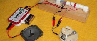
And again I encountered the same problem that the kick pad moves like hell together with the pedals! I swore and swore, and then I thought: if he, the nit, drives, why not Secure him?! And that’s where my IDEA was born! Take a piece of plywood and firmly screw this damn pad there! And at the same time, display on it everything else that I need for training or for fun!
So, cardan! That's his name, and it's actually a well-established term in the drums. It is needed so that you can play complex structures with your feet. As far as I know, this invention appeared when bands began to travel a lot, and it was difficult to carry an extra kick (bass drum) with them to clubs. The double pedal doesn't need a second kick because it has two beaters that hit the same kick. In fact, playing two separate kicks may be easier, because each foot will have its own pedal and bounce off the head. Many people say that when the plastic on a barrel vibrates from the impact of one foot, it is harder to hit it with the other. But I don’t know - now almost everyone uses a gimbal, and somehow they don’t swear at it.
Here's how it works. On the right we have a pedal with two beaters. The beaters, and in general all the mechanics, are mounted on bearings, because they are subject to crazy loads here. If you put your finger under the beat of the mallet and stomp it hard, I think the finger will easily break. And all this is also played at a fast pace.
On the left there is another pedal, which is connected to the right through the so familiar to all motorists (which is why I mentioned all this at the beginning of the post) CARDAN SHAFT! =) This is where the name of this double pedal comes from.
Using the gimbal (double kick play)
This is what the cardan looks like up close. It has two connections: one near the right pedal, and one near the left. Thanks to this, we can place our pedals at the angle we need and play calmly.
The most important joint of the cardan (Iron Cobra)
You, of course, noticed the cotton pads nearby. Damn, I distinguished myself again! =) I play for myself, I play... and I think: “It’s creaking for some reason. Well, it’s probably my pedal that’s rubbing against the bolts with which I attached it.” And then it only dawned on me that I had never lubricated this cardan since the moment of purchase, because it just sat there most of the time!
I started to lubricate it - and from there it started pouring with rust! My God!! It was tough! I spilled oil all over, washed off the rust, and then discovered that there were a lot of rusty oil splashes around the cardan joints on the plywood. Remember the force that the mechanics experience? There is nothing particularly loose in the cardan, but during the moments of the game oil splashed out of it! So I put some cotton wool on it so that the oil would remain there, but not splatter. By the way, you will need to lubricate it again.
Well, none of this would have happened if it weren’t for the plywood. Initially, I wanted to rigidly screw the pad and pedal onto the plywood. But then my principle “Do with reserve for the future and as flexibly as possible” took its toll and I figured out how to secure the pedal so that it would not go anywhere, but also so that it could (if necessary) be removed and dragged onto the turnip. Well, what if? Funt is the former bass player, isn't it?
I arranged everything on the plywood the way it would stand and marked the positions of all the pedals with a pencil. And then I took M6 screws and started fastening everything with them.
We mark the plywood in order to secure everything firmly to it.
I unscrewed the rubber drum pad from its stand. I drilled the stand itself and screwed it to the plywood. My plywood is thin and it was bent a little, but this is a small thing compared to how all this crawled and jumped before.
We attach the stand from the Gibraltar kick drum training pad to the plywood
The front edge of the pad, where there is a groove for pressing the pedal, is slightly raised, and therefore I can remove the pedal without problems.
I did something brutal with the left leg part of the pedal. There are screws with sharp edges that are supposed to rest the pedal against the floor. But if we have plywood, then why bother spoiling it with these stops when we can make support screws? Without thinking twice, I drilled a couple of holes in the pedal, and now with one easy movement it is placed on the protruding screws and does not move anywhere.
We place emphasis on the left pedal of the cardan so that it does not move away
Like this:
The left pedal of the cardan is bolted and does not go anywhere, but it can be removed
The screws give a slight play, so the cardan shaft and this pedal feel calm, they don’t bend anywhere when playing, but at the same time they don’t go anywhere.
I played so-so, I played. I even asked my neighbors - they say, am I bothering you? They said I wouldn't interfere. Well, let's continue to learn how to play with our feet. It's very difficult and I've never done it. The hardest thing is that when you learn something for the foot, you play it slowly and strain to keep the tempo. And then, as soon as you relax, having mastered this very tempo, then personally my leg immediately tries to play faster and, of course, gets lost.
So I tested for myself the most important recommendation when playing with legs - start playing VERY SLOWLY and under no circumstances rush! Well, the simplest thing I want to film is to learn how to play a solo from the Panic Attack song. I found a video on YouTube, but Portnoy explains how it all plays. The song is interesting, and I took pictures of some of the things, but I still can’t do it with the legs.
The point of the joke with the solo (you need to watch the video from the 7th minute) is that the legs here constantly play the same thing (right-left), but the hands play either in the usual 4/4 or 3/4 version. What is heard by ear is that sometimes the hands sound at the same time as the legs, and sometimes the legs seem to sound more often than the hands. This is an incomprehensible difficulty for me now, and I’m training!
Well, you can watch the full version here (solo starts at 4:50):
For me, the most difficult thing is to quickly change the rhythm. And I can’t even get the introduction right, but something is already emerging, even if it’s porn! Here you go:
In general, I’m training, I’m trying to get my head around something, and I’m starting to like something... and then HOOP! Why don't your legs feel right? How do they hit something soft?.. Uh... and then the elastic of the pad just FUCKING FALLS AWAY!
When I saw how this pad was made, I screamed obscenities!! The entire pad, which is hit as hard as you can with the pedal, is held on by a NUT EMBRACED IN THE PLASTIC!! And at the same time, this is not some kind of handicraft, but a standard training pad for feet from the Gibraltar company, which is actually famous for its hardware (stands, frames for drums). And this is just a fabulous kick!
The Gibraltar training pad is broken! =)
I opened this pad, marveled at the foam pancake inside (which was almost crumbling in the center), and naively thought that now I would make a large iron washer and screw it back with a small nut using heads. But no! Another surprise awaited me. This entire pad is attached to a bolt on the stand. The bolt is welded rigidly to the rack from the inside, and the threads on it are NOT METRIC!! Aah, bastards!!!
The Gibraltar training pad is broken! =)
That is, either it will be necessary to redo the whole thing and cut the bolt, then look for a new one, or look for something else. Hm. From another I had a piece of iron lying around, on which I was going to test a hydraulic press for punching holes. It is quite thin, and then I decided to test the press on a powerful junction box, which a harsh oil worker gave me as a gift (and almost burned the screwdriver). I cut a piece from the piece of iron and screwed it on with screws at random:
Making a new pad mount from a piece of iron
The screw nuts stick out from the inside, but the pedal beaters do not reach there due to the tension of the rubber. Although maybe I’ll open the pad and, if the rubber starts to wear out, I’ll shove some more rags in there.
Making a new pad mount from a piece of iron
Well, then I screwed this structure tightly to the rack. Something has changed, because previously the pad, due to this fucking nut, oscillated and imitated the softness of the plastic on the kick drum. Now it sits more rigidly and my legs are getting used to it again. I don't know if this is good or bad, but it seems to be playing.
We firmly attach the drum pad to a standard stand.
This is what it looks like now:
What happened in the end
This is the story with my three pedals. Put me in the car right now, and I’ll play something like that on the pedals! =)
Finale - clean and beautiful stands
By the way, the nuts that hold the screws that tighten the rubber of this pad are also fused into the plastic just like that. So maybe this is not the end of the story... =)
Installing the pump
Next we must choose the “right” water pump. The range of these tools today is so wide that you can find a model of any strength and size. We only need to pay attention to two things:
- Will the engine be able to spin this pump;
- Is it (the pump) centrifugal?
Next, the pump is installed in the same frame; if necessary, additional fasteners are attached.
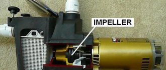
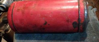
The body of a vortex generator is a cylinder, closed on both sides. There should be through holes on the sides through which the device will be connected to the heating system. But the main feature of the design is inside the body: a nozzle is located immediately near the inlet. The nozzle hole must be selected purely individually.
Note! It is desirable that the nozzle hole be half as large as 1/4 of the total diameter of the cylinder. If the hole is smaller, then water will not be able to pass through it in the required quantity and the pump will begin to heat up. Moreover, internal elements will begin to be destroyed by cavitation.
To make the case we will need the following tools:
- Iron pipe with thick walls with a diameter of about 10 cm;
- Couplings for connection;
- Welding;
- Several electrodes;
- Impeller;
- A pair of pipes with threads;
- Electric drill;
- Drill;
- Adjustable wrench.
Now - directly to the manufacturing process.
- To begin with, we cut off a piece of pipe about 50-60 cm long and make an external groove on its surface about half the thickness, 2-2.5 cm. We cut the thread.
- We take two more pieces of the same pipe, each 5 cm long, and make a couple of rings from them.
- Then we take a metal sheet with the same thickness as the pipe, cut out original covers from it, and weld them where the thread was not made.
- We make two holes in the center of the covers - one of them around the circumference of the pipe, the second around the circumference of the nozzle. Inside the cover next to the jet we drill a chamfer so that we get a nozzle.
- We connect the generator to the heating system. We connect the pipe near the nozzle to the pump, but only to the hole from which water flows under pressure. We connect the second pipe to the entrance to the heating system, but the output must be connected to the pump inlet.
The pump will create pressure, which, acting on the water, will force it to pass through the nozzle of our design. In a special chamber, the water will overheat due to active mixing, after which it is supplied directly to the heating circuit. In order to be able to regulate the temperature, the vortex heat generator must be equipped with a special locking device located next to the pipe. If you slightly cover the constipation, the structure will take longer to move water through the chamber, therefore, the temperature will rise because of this. This is how this kind of heater works.
Read about other alternative heating methods here
Other types of mechanical pumps
Manual mechanical water supply devices have been used since ancient times and have now been replaced by industrially produced models. In some cases, in the absence of electricity, the use of mechanical factory units is ineffective, and craftsmen come up with their own diagrams and drawings on how to make a hand pump for a well with their own hands.
If in the above case (water intake from a well) the principle of operation of industrial units can be used, then for water intake from open reservoirs they use their own developments based on ancient technologies.
Archimedes screw
Archimedes screw and its uses
The design was invented by a Greek thinker in 250 BC and consists of a cylindrical pipe, inside of which there is a screw; the system is lowered into an open body of water at a slight angle. During operation, the rotating blades capture water and move it up the pipe, at the end of which it is poured into the prepared container.
An analogue of this installation is an electric screw pump designed for constant water intake from deep water sources.
Hydraulic ram
Hydraulic ram
Mechanic Montgolfier is the creator of a hydraulic pump that raises water using its kinetic energy. Its principle of operation is to shut off the fast flow with a valve, after which water under pressure enters the hydraulic tank located above and is then delivered to the consumer through a floor hose. The device operates in repeating cycles; some manufacturers produce hydraulic pumps using artisanal methods.
Airlift
Aerolift - operating principle
The German engineer Karl Loscher developed this method in 1797; its essence consists of pushing out liquid from a hollow pipe lowered into a source with air. To operate the airlift, air is pumped into the lower part of the pipe through the inlet pipe using a hand pump; its bubbles dissolve in water and, due to their light weight, rise to the surface along with the liquid.
To prevent liquid from entering the pressure air hose, inflation is carried out through the nipple.
This design can be used in the presence of electricity by connecting a compressor instead of a mechanical pump.
Homemade piston pump
Some craftsmen make piston pumps themselves. The usual design consists of a working chamber made of a welded pipe; a metal or plastic disk with a rubber sealing ring along the diameter is used as a piston. To ensure water supply using a homemade design, holes are drilled in plastic or metal piston discs to install a check valve system.
Homemade piston pump design
Most modern mechanical units, like surface electric pumps, are capable of lifting liquid from wells up to 10 meters deep. The highest delivery height is provided by a rod pump, which operates in a similar way to electric submersible types. Its body and operating valve can be lowered into a source up to 30 meters deep, providing intake at a similar distance to the water surface.
Among all types in everyday life, the most common are piston hand pumps, which are mounted directly above the outlet of the casing well pipe, with suction occurring through a pipe lowered into the hole with a check valve.
Increasing productivity
The pump loses thermal energy, which is the main disadvantage of the vortex generator (at least in its described version). Therefore, it is better to immerse the pump in a special water jacket, so that the heat emanating from it is also beneficial.
The diameter of this jacket should be slightly larger than that of the pump. We can use a piece of pipe for this, according to tradition, or we can make a parallelepiped from sheet steel. Its dimensions must be such that all elements of the generator fit freely into it, and its thickness must be such that it can withstand the operating pressure of the system.
We insulate the VTP
First of all, we put on the casing. To do this, take a sheet of aluminum or stainless steel and cut out a couple of rectangles. It is better to bend them along a pipe that has a larger diameter, so that a cylinder is eventually formed. Next we follow the instructions.
- We fasten the halves together using a special lock used to connect water pipes.
- We make a couple of covers for the casing, but do not forget that there should be holes in them for connection.
- We wrap the device with thermal insulating material.
- Place the generator in the housing and close both covers tightly.
There is another way to increase productivity, but for this you need to know how exactly Popov’s miracle device works, the efficiency of which can exceed (not proven and not explained) 100%. You and I already know how it works, so we can proceed directly to improving the generator.
Causes of malfunctions
There are many different reasons for a sewing machine pedal to break down. However, this does not mean that repair work will be necessary in every case. First, you need to make sure that it is the pedal that has broken, and not some other part.
First you need to check the serviceability of the motor. To do this, you need to directly connect the cord coming from the outlet to it. If the cause of the breakdown is not the motor, then you need to look at what type of pedal the sewing machine has. If it is electrical, you can begin to repair it. It is impossible to repair an electronic pedal yourself. It is worth familiarizing yourself with the most common reasons for its breakdown.
- If the contacts in the pedal itself or in the plug become oxidized, it will be enough to simply clean them and then restore them. Then the sewing machine will work again. This can be done using regular sandpaper, which will not damage them when cleaning.
- Quite often the electrical circuit inside the insulating cord breaks. This happens as a result of careless handling of the connecting wires that go to the pedal. For example, if you frequently pull the cord out of the outlet for no reason, and pull it by the cord rather than the plug, the machine may break. In addition, very often heavy objects fall on the cord or a chair leg gets caught. In this case, you just need to replace the wire.
However, doing the repairs yourself is dangerous in this case, so it would be better to seek help from an electrician.
- Another reason for a sewing machine to malfunction is burnout, as well as replacement of graphite plates. The first sign of such a breakdown is a decrease in the speed of the electric drive of the sewing machine. In addition, when you press the pedal, the electric motor responds too weakly. The machine starts sewing only a couple of seconds after pressing the pedal, and not immediately. If you open the lid and look at the graphite plates, you can only see black dust. In this case, they must be replaced with new ones. However, it will not be possible to purchase them in the store. In addition, you cannot cut them with a hacksaw either. After all, the thickness of one plate is only 0.2 millimeters.
In addition, graphite crumbles too quickly and it will be impossible to saw it off evenly. Therefore, in the event of such a malfunction, it is necessary to purchase a new part completely and then replace it.
- Most often, the rheostatic pedal of a sewing machine is made of heat-resistant plastic, which differs from other materials in its fragility. Therefore, if heavy objects fall on the plastic pedal or if it accidentally falls on the floor, it may break. In this case, some seamstresses try to glue it together using high-quality glue. However, the pedal of an electric sewing machine tends to heat up, which is why the glue softens during prolonged use and the parts that were connected by it become fragile. Therefore, when you press the pedal with your foot, it can simply fall apart, and in some cases even shock the seamstress. Therefore, it is better to replace it with a new one.
- In electronic sewing machines, you can also notice that such an important part as the pedal does not work. However, a malfunction can only be detected using special instruments. Quite often the microcircuit fails or the thyristor is simply faulty. In this case, the parts must be replaced with new ones. It is best to do this in specialized centers, where specialists will give their verdict after inspecting the pedal. However, some experienced craftsmen who have little skill in working with electronic equipment try to do it themselves.
Repair is absolutely no different from repairing an electric pedal. You also need to open the pedal, carefully examine all suspicious places, and then solder them with a soldering iron.
In addition, every seamstress should know several rules for using a sewing machine. First of all, after completing the repair, especially if you did it yourself, you should not leave the sewing pedal turned on for a long time. In addition, you should not leave it unattended until the seamstress is sure that it is in full working order. In any case, when the seamstress takes her foot off the pedal, no current should flow to the electric motor, especially at the output contacts going to the plug. After all, in this case there is a complete disconnection of the electrical circuit.
Very often, newly minted masters have no experience in adjusting the rheostat. Therefore, quite often they leave the pedal on. And this will lead to its constant overheating, which means an early breakdown.
To summarize, we can say that such a part as the sewing machine pedal is quite important. After all, without it the machine itself will not work. Therefore, if it malfunctions, you need to quickly run to a technician or solve the problem yourself. Otherwise, work will stall for a long time.
Repairing a sewing machine pedal is demonstrated in the video.
The pedal for a sewing machine is the trigger mechanism for starting the entire operation of the machine. This applies to modern electric options. Craftsmen who switched to working with hand-held devices remain delighted with the convenience and comfort of the process. They realize that a malfunction of the pedal can cause a lot of inconvenience in the operation of the equipment, so they are ready to repair the pedal for the sewing machine with their own hands. If you know all the features and components of its work, it will not be difficult to do.
Vortex damper
Yes, we will make a device with such a mysterious name - a vortex damper. It will consist of plates arranged lengthwise, placed inside both rings.
Let's see what we need for the job.
- Welding.
- Turbinka.
- Sheet of steel.
- Pipe with thick walls.
The pipe should be smaller than the heat generator. We make two rings out of it, about 5 cm each. We cut several strips of the same size from the sheet. Their length should be 1/4 of the length of the device body, and their width should be such that after assembly there is free space inside.
- We insert the plate into the vice, hang metal rings on one end of it and weld them to the plate.
- We take the plate out of the clamp and turn it the other way. We take the second plate and place it in the rings so that both plates are placed parallel. We fasten all the remaining plates in the same way.
- We assemble the vortex generator with our own hands, and install the resulting structure opposite the nozzle.
Note that the scope for improving the device is almost limitless. For example, instead of the above plates, we can use steel wire, first twisting it into a ball. In addition, we can make holes in plates of various sizes. Of course, none of this is mentioned anywhere, but who says you can't use these improvements?
And as a conclusion, here are some practical tips. Firstly, it is advisable to protect all surfaces by painting. Secondly, all internal parts should be made of thick materials, since it (the parts) will constantly be in a fairly aggressive environment. And thirdly, take care of several spare caps that have different hole sizes. In the future, you will select the required diameter in order to achieve maximum performance of the device.
The cavitation heat generator is characterized by good efficiency and compactness. It is rare that an owner does not try to save on heating or the consumption of other benefits, which become more and more expensive every year. To make the heating system of a residential or industrial premises economical, many people resort to various schemes and methods for generating thermal energy. One of the devices suitable for these purposes is a cavitation heat generator.
What you will need
- Plywood. To make the five sides of the box you will need plywood, approximately 1.2 cm thick. The main part of the tool will consist of this material. This thickness will allow the cajon to surely support the weight of an adult. For tapa, the wall of the instrument on which the blows are made, smaller plywood is used, approximately 3 mm thick. As you play, the tapa will vibrate, creating sound, and thin material comes in handy here;
- Snare snare snare wire, regular wire, or guitar strings. To create the necessary characteristic timbre of a cajon, additional elements are installed inside it, in the form of wire or a snare snare snare. When the cajon is struck, this part of the structure creates a cracking sound, vibrating along with the tapa;
- A wooden block, approximately 30 mm thick, for attaching the snare;
- Rubber or cork “spots”, 4 pieces. Used to make legs;
- Clamps and belts for tightening the walls of the cajon when gluing;
- Self-tapping screws, wood glue and nails;
- Saw, sander, sandpaper, screwdriver, drill and jigsaw;
- Varnish or other paint coating.
What is a vortex heat generator
A cavitation vortex heat generator is a simple device that can effectively heat a room while spending a minimum of money. This occurs due to the heating of water during cavitation - the formation of small steam bubbles in places where the liquid pressure decreases, which occurs either during pump operation or during sound vibrations.
A cavitation heater is capable of converting mechanical energy into thermal energy, which is actively used in industry, where heating elements can fail when working with a liquid that has a large temperature difference. Such a cavitator is an alternative for systems operating on solid fuel.
Advantages of vortex cavitation heaters:
- Economical heating system;
- High heating efficiency;
- Availability;
- Possibility to assemble with your own hands.
The vortex heat generator should not be located near a living space due to its high noise level
Disadvantages of the device:
- When assembling it yourself, it is quite difficult to find materials to create the device;
- Too much power for a small room;
- Noisy operation;
- Considerable dimensions.
Less popular manual modifications
In addition to piston models, which have proven themselves well in factory and homemade versions, other devices are also used.
They are less productive, but interesting from the point of view of design and operating principle.
Image gallery
Photo from
Bike pump
Wooden model with flexible stem
Membrane type device
Structure from a sleeve and a wheel
There are factory models that are not practical to make yourself. For example, equipment based on an impeller. Such devices are used in the industrial sector; they are not very convenient for the garden.
In addition, buying a compact metal device that looks like a can twister will cost no more than making it yourself.
None of the considered homemade pump designs suits you? Then we recommend that you look at more homemade options, the production of which we discussed in the next article.
Standard design of a heat generator and its operating principle
The process of cavitation is expressed in the formation of vapor bubbles in a liquid, after which the pressure slowly decreases at high flow rates.
What can cause steam formation:
- The occurrence of acoustics caused by sound;
- Radiation of a laser pulse.
The closed air regions mix with water and go to a place with high pressure, where they collapse with the radiation of a shock wave.
Operating principle of the cavitation apparatus:
- The water jet moves through the cavitator, where the pump creates water pressure that enters the working chamber;
- In the chambers, the fluid increases speed and pressure using various tubes of different sizes;
- In the center of the chamber, the flows mix and cavitation appears;
- In this case, the steam cavities remain small and do not interact with the electrodes;
- The liquid moves to the opposite end of the chamber, from where it returns back for the next use;
- Heating occurs due to the movement and expansion of water at the exit of the nozzle.
This is how a vortex cavitation heater works. Its device is simple, but allows you to quickly and efficiently heat the room.
Purpose of manual models
The main purpose of using pump-type equipment is to pump water from a source to certain points: to a residential building, bathhouse, garage, garden. In suburban areas, the source most often is wells and wells, less often - ponds and other bodies of water.
All residential or country houses can be divided into three categories: permanent, seasonal and periodic residence. Not all of them have electricity, and some are supplied irregularly.
If we summarize all these factors, we can draw the following conclusions:
- in permanent residences, electricity is used by default, so the main equipment for pumping water is an electric pump, and the manual model is a spare backup unit;
- if the cottage is used only in the summer and power lines are connected, then the energy-dependent option is also ideal, and the manual device plays a secondary role;
- a summer cottage without electricity most of all needs manual equipment.
To irrigate 2-3 flower beds, you can still draw water with buckets, but to ensure complete and daily watering of beds, greenhouses and lawns, a pump is needed. This is where a model that requires a pair of hands to operate comes in handy.
You can make a simple speaker yourself by using the skills of welding and assembling metal or plastic parts.
An example for making your own model can be a factory product assembled from durable cast iron or steel parts, with a comfortable handle for use
Some craftsmen build reliable equipment for wells and wells that serves well for years. We present an overview of homemade products, for the manufacture of which scrap materials were used.
Economical DIY cavitation heat generator
It is quite possible to create a homemade vortex generator with cavitation if you carefully study the drawings and diagrams of the device, and also understand its operating principle. Potapov’s VTG with an efficiency of 93% is considered the easiest to create independently, the circuit of which is suitable for both home and industrial use.
Before you begin assembling the device, you should choose the right pump, based on its type, power, required thermal energy and pressure value.
Basically, all cavitation generators have a nozzle shape, which is considered the simplest and most convenient for such devices.
What is needed to create a cavitator:
- Pressure gauges;
- Thermometer for measuring temperature;
- Output and inlet pipes with taps;
- Valves for removing air pockets from the heating system;
- Thermometer sleeves.
You also need to monitor the cross-sectional size of the hole between the diffuser and the confuser. It should be approximately 8 - 15 cm, neither narrower nor wider.
Scheme for creating a cavitation generator:
- Selecting a pump - here you need to decide on the necessary parameters. The pump must be able to work with high-temperature liquids, otherwise it will quickly break down. He must also be able to create a working pressure of at least 4 atmospheres.
- Creating a cavitation chamber - the main thing here is to choose the right cross-sectional size of the passage channel. The best option is 8-15 mm.
- Choosing a nozzle configuration - it can be in the form of a cone, a cylinder, or simply be rounded. However, the shape is not as important as the fact that the vortex process begins as soon as the water enters the nozzle.
- Making a water circuit - outwardly it is a curved tube leading from the cavitation chamber. It is connected to two sleeves with a thermometer, two pressure gauges, and an air valve, which is placed between the inlet and outlet.
The body of the cavitation heat generator can be painted in any color
After creating the housing, the heat generator should be tested. To do this, the pump should be connected to electricity and the radiators to the heating system. Next comes connection to the network.
It is especially worth looking at the pressure gauge readings and setting the desired difference between the inlet and outlet of the liquid within 8-12 atmospheres.
Next, water is allowed into the system. If it heats up in 10 minutes by 3-5 degrees per minute, that’s good. In a short time the liquid will warm up to 60 degrees. This is quite enough for work.
How to repair a sewing machine pedal with your own hands
Is it possible to repair a damaged part yourself? If it is a rheostat sample, then even the craftswoman herself can try to do it. To do this, at the first sign of a problem, you can simply try to move the rheostat housing. Perhaps this very method will help regulate smooth operation.
But not every specialist from a sewing machine repair shop can cope with the difficulties posed by a breakdown of a pedal with an electric motor. Here it would be most logical to advise even contacting a person who does repairs in television workshops. Such a professional will definitely check the following points:
- Are the contacts from the connecting plugs oxidized? If so, you can simply clean them with sandpaper.
- Is the wire inside the insulation broken? But this is where a tester comes in handy to determine the problem. By the way, if there is a break in one place, it is best to replace the entire wiring (which, again, is more logical to entrust only to a specialist).
- Has the main radio component called a thyristor failed, which can only be replaced by a person knowledgeable in this matter?
Preventing problems with your sewing machine pedal
There are a number of measures, the observance of which will push aside the issue of repairing this device (as it is unnecessary). The rules are simple:
- Care should be taken to handle the part itself, which has a fragile body.
- It is important not to leave the sewing pedal plugged in for a long time. This action can lead to overheating of the part.
DIY heat generator (video)
A cavitation heater is quite an interesting and economical way to heat a room. It is easily accessible and can be created independently if desired. To do this, you need to purchase the necessary materials and do everything in accordance with the diagrams. And the effectiveness of the device will not take long to show itself.
For heating rooms or heating liquids, classic devices are often used - heating elements, combustion chambers, filaments, etc. But along with them, devices with a fundamentally different type of effect on the coolant are used. Such devices include a cavitation heat generator, the work of which is to form gas bubbles, due to which heat is released.
DIY pedal for a machine – Machine tools, welding, metalworking
Engraving equipment, with which you can successfully perform various technological operations, is now actively used by both specialists and home craftsmen.
Although purchasing such a device on the modern market does not present any problems, many of those who would like to have it in their workshop do otherwise and make an engraver with their own hands.
Homemade engraver with a holder from a dental drill
Despite the simplicity of the design, a homemade engraving machine allows you to successfully perform the same technological operations as a serial model engraver. Such operations, in particular, include:
- milling of flat and shaped surfaces, as well as holes and grooves of various configurations;
- drilling and boring small diameter holes;
- cutting thin sheet material;
- cleaning the product from traces of corrosion and other persistent contaminants;
- applying inscriptions and patterns to the treated surface;
- grinding and polishing.
A homemade engraver with a sandpaper attachment is great for grinding surfaces in hard-to-reach places
The materials that a homemade electric engraver can process are metal, wood, plastic, ceramics, glass, bone, artificial and natural stone.
What you need
The functionality, reliability and technical characteristics that a homemade engraving machine will have depend entirely on what materials and mechanisms you will use to make it.
Almost any electric motor can be turned into an engraving machine by adding a flexible shaft with a holder
To make a simple, but easy to use and functional engraver, you will need the following components.
- A flexible shaft and a working attachment for it, in the clamping mechanism of which the tool will be fixed. As a flexible shaft for the engraver, you can use the drive shaft from a drill or a cable that drives the speedometer of a car or motorcycle. The working attachment can also be removed from the drill or made independently from a block of textolite, grinding it to the required diameter and drilling a stepped hole in its inner part. The diameter of the hole in the working nozzle of the engraver must be selected in such a way that its walls reliably hold the stationary part of the drive cable, but at the same time do not interfere with the rotation of its movable core. A tube is inserted into the hole in the front part of such a homemade working attachment, inside which a clamping chuck made of two halves, fastened together with a screw, rotates freely. The chuck, which must be balanced, can accommodate a tool with a shank diameter in the range of 2–5 mm.
- A set of tools with which processing will be performed. If you use a drill handle as a working attachment for a homemade engraver, then the tools should also be from dental equipment that match the diameter of the shanks. For a homemade working attachment, as mentioned above, any tool with a shank diameter of 2 to 5 mm is suitable.
- A drive electric motor, which can be used as any motor powered by an electric current of 220 volts. This could be a motor from a DVD player or from an old reel-to-reel tape recorder, washing machine, or any other household appliance you don't use. An electric motor from a sewing machine is optimal for a homemade engraver, because it is already equipped with a rheostat, which allows you to regulate the shaft rotation speed within a fairly wide range. Such motors, as a rule, are capable of shaft rotation speeds of up to 6 thousand rpm, which is quite enough for a household engraver.
Design of a homemade engraving machine with a flexible shaft
Machine parts
Drawings of engraver parts Bed Casing Bracket and clamp Bushing and angle Holder Electric motor connection diagram
To make an engraver, you will also need an electric drill, a sharpening machine and a standard set of bench tools.
The principle of operation of a homemade engraving machine
The homemade engraver of the proposed design works according to the following principle. Rotation from the electric motor is transmitted through pulleys and a rubber belt to a flexible shaft, which, in turn, communicates it to the working attachment and the tool fixed in it.
A do-it-yourself engraving machine can be made in another design, which assumes that the flexible shaft is connected to the electric motor via an adapter coupling.
At one end, such a coupling is mounted on the electric motor shaft and securely fixed on it with a pin, and the movable core of the flexible shaft is inserted into a square hole made at its other end.
The device of the simplest homemade engraver
After all the structural elements of the future homemade engraver are prepared, they begin to manufacture it.
- For reliable and stable fastening of all structural elements of the engraver, it is necessary to make a simple base frame, for which you can use a sheet of textolite or thick plywood, cutting out a piece of the required size from it. At pre-marked places on the surface of such a base, an electric motor and a bracket with a clamp are attached, in which the rear tip of the flexible shaft will be fixed. After tightening the fastening nut on the bracket clamp, the end of the flexible shaft should be securely fixed in it.
- Pre-prepared pulleys, which can also be removed from old household appliances, are fixed on the electric motor shaft and on the movable core of the flexible shaft. To perform such fixation, it is necessary to drill holes in the flange part of the pulleys and on the shafts into which pins will then be inserted. Regular epoxy resin will help ensure the reliability of the connection. The transmission of rotation from an electric motor to a flexible shaft, carried out using pulleys and belts, is convenient in that by changing the diameters of the pulleys used, you can adjust the frequency of rotation transmitted to the grower.
- The final stages of manufacturing an engraver of the proposed design are installing a rubber belt on the pulleys of the flexible shaft and electric motor, connecting the motor to electrical power, fixing the working attachment with the tool at the front end of the flexible shaft and testing the finished device.
Grinder machines
Finding a ready-made machine that meets your needs in stores is not difficult. However, the likelihood of finding a design that rigidly fixes the angle grinder and does not move during operation is not great, since they are all made of duralumin.
For this reason, people who have machines improve or remodel them in every possible way. But there are many serious obstacles here - the materials of the machine are difficult to weld, or, for example, the design does not take into account points that are important for you - for example, an accurate ruler or a more elastic spring.
Remaking someone else's is a more difficult task than making your own!
Purchased version of the grinder holder
Making the simplest device for an angle grinder can be done at minimal cost and within a few hours! In fact, the structure will be a long metal pipe, which is both a frame and a handle. At one end, a transverse metal strip is welded, which has two holes for fastening the grinder.
A more reliable homemade version of the grinder holder
From the same edge, the pipe is attached to a small piece of angle on the movable shaft. The corner itself can be attached to the desktop or to the floor! A spring should be fixed on the opposite side of the fastener, returning the entire structure to its original position.
first option
second manufacturing option
third manufacturing option
That's all - the manufacture of the machine is completed, all that remains is to properly secure the angle grinder. Naturally, this option should be used for simple work, and if precise and complex procedures are required, then the design should be more complex.
Making a cutting machine from a grinder for precision work!
Such accessories for an angle grinder as a cutting machine are made using the following materials and tools: a steel angle, a profile pipe, a metal sheet for the platform (chipboard can be used), a welding machine, a channel, a drill, a shaft, several bearings, a pipe with a small diameter, springs, relays and pedals. Welding, in principle, can be replaced with strong bolts - here you will have to use a drill.
It is worth noting that with this implementation of the machine, it can be easily disassembled if such a need arises.
first design option
first design option
Parts and fasteners
We start making the machine from the frame. Each grinder will require an individual design, since each manufacturer produces grinders of its own design - in some you will have to remove the handle, and in others you will need to invent a stand for the entire grinder as a whole! In addition, different frames are needed for different disc diameters.
Frame
The simplest frame consists of two frames and a common axis. The lower frame must be fixed on top of a metal or chipboard platform. For a large grinder, it is better to use metal.
It is necessary to ensure rotation of the upper frame on which the angle grinder is attached relative to the lower frame in a vertical plane, like a pendulum. To fix the starting position, you will have to use a spring.
A fastener should be welded onto the lower frame, which includes a clamping angle and a movable clamp.
Second design option
Second design option
Ruler - for this particular case, you can use a movable ruler with a limiter, which is welded onto the tube. It adjusts the accuracy of the size, after which it is secured using an end screw!
Electronics. To increase the usability of your machine, you need to provide such things as a start pedal or button (switching using a 12 V low-voltage relay). Using this pedal, voltage will be supplied to the grinder.
DIY accessories for an angle grinder
With the help of such a simple device for an angle grinder, we can free our hands and at the same time make an accurate, even cut without using a vice, and saving time on measurements also plays an important role. Using this design, a cutting saw for metal can be replaced, and if suddenly necessary, the grinder can be easily dismantled.
DIY pedal for a machine – Machine tools, welding, metalworking
Engraving equipment, with which you can successfully perform various technological operations, is now actively used by both specialists and home craftsmen.
Although purchasing such a device on the modern market does not present any problems, many of those who would like to have it in their workshop do otherwise and make an engraver with their own hands.
Homemade engraver with a holder from a dental drill
Despite the simplicity of the design, a homemade engraving machine allows you to successfully perform the same technological operations as a serial model engraver. Such operations, in particular, include:
- milling of flat and shaped surfaces, as well as holes and grooves of various configurations;
- drilling and boring small diameter holes;
- cutting thin sheet material;
- cleaning the product from traces of corrosion and other persistent contaminants;
- applying inscriptions and patterns to the treated surface;
- grinding and polishing.
| Foot switches VPN-1 and VPN-2 are manufactured at our own production in Russia (NPP IMZ). They are equipped with a domestically produced microswitch with a high degree of reliability. The parts of the VPN pedal housing are made from sheet steel using laser cutting and bending on high-quality CNC machines from the Swiss company Trumpf. The body is painted with powder paint on an industrial conveyor painting line or with black acrylic enamel (depending on the batch). Foot switches or switches , which are also called foot switches or foot pedal , are recommended for switching electrical control circuits of alternating and direct current on various machines, devices, equipment in places and objects where this is due to the conditions of use, safety rules, design and simply convenience . | |
| Price : 3500 rubles | Price : 5800 rubles |
| Single open foot switch VPO-1 Foot pedal VPO-1 250 V / 10 A | Double open foot switch VPO-2 Foot pedal VPO-2 250 V / 10 A |
| Price : 3200 rubles | Price : 5400 rubles |
| Triple open foot switch VPO-3 Foot pedal VPO-3 250 V / 10 A | Foot switch triple open VPN-3 Foot pedal VPN-3 250 V / 10 A |
| Price : 8800 rubles | Price : 9300 rubles |
Foot pedals are used on machines of various modifications and models.
Application of foot switches
In general, pedal switches ( foot pedal ) are classified as control switches.
Pedal (foot) switches (switches) are widely used in many industries and various areas of our lives.
You can find a foot pedal at engineering enterprises and enterprises of the light and food industries, in medical institutions and in transport, in cargo terminals and control rooms.
Using foot switches (machine pedals), you can control woodworking or metalworking machines, such as: bending machines, presses, shears (guillotines), automatic welding machines and machines, stationary and hand-held power tools, edge banding machines, cargo winches, drives of electric vehicles and diesel locomotive control circuits , dental equipment, operating room equipment, etc.
Design and principle of operation
The principle of operation of a cavitation heat generator is the heating effect due to the conversion of mechanical energy into thermal energy. Now let's take a closer look at the cavitation phenomenon itself. When excess pressure is created in a liquid, turbulence occurs, due to the fact that the pressure of the liquid is greater than that of the gas contained in it, gas molecules are released into separate inclusions - the collapse of bubbles. Due to the pressure difference, water tends to compress the gas bubble, which accumulates a large amount of energy on its surface, and the temperature inside reaches about 1000 - 1200ºС.
When cavitation cavities move into the normal pressure zone, the bubbles are destroyed, and the energy from their destruction is released into the surrounding space. Due to this, thermal energy is released, and the liquid is heated by the vortex flow. The operation of heat generators is based on this principle; then consider the principle of operation of the simplest version of a cavitation heater.
The simplest model
Look at Figure 1, here is a device of the simplest cavitation heat generator, which consists of pumping water to the point where the pipeline narrows. When the water flow reaches the nozzle, the liquid pressure increases significantly and the formation of cavitation bubbles begins. When leaving the nozzle, the bubbles release thermal power, and the pressure after passing the nozzle is significantly reduced. In practice, multiple nozzles or tubes may be installed to increase efficiency.
Potapov's ideal heat generator
The ideal installation option is the Potapov heat generator, which has a rotating disk (1) installed opposite the stationary one (6). Cold water is supplied from the pipe located at the bottom (4) of the cavitation chamber (3), and the already heated water is discharged from the top point (5) of the same chamber. An example of such a device is shown in Figure 2 below:
Rice. 2: Potapov cavitation heat generator
But the device was not widely used due to the lack of practical justification for its operation.
The main task of a cavitation heat generator is the formation of gas inclusions, and the quality of heating will depend on their quantity and intensity. In modern industry, there are several types of such heat generators, differing in the principle of producing bubbles in the liquid. The most common are three types:
- Rotary heat generators - the working element rotates due to an electric drive and produces fluid turbulence;
- Tubular - change pressure due to a system of pipes through which water moves;
- Ultrasonic - the heterogeneity of the liquid in such heat generators is created due to low-frequency sound vibrations.
In addition to the above types, there is laser cavitation, but this method has not yet found industrial implementation. Now let's look at each type in more detail.
Device
The pedal circuit for a sewing machine is most often very simple. This is especially true for parts that are completely devoid of electronic parts. Most often they occur in foot-operated electric machines. They are called rheostatic pedals. Such a pedal consists of one part - a rheostat, which has a large number of graphite plates that fit very tightly to each other. It acts as a switch or switch for the electrical drive of the machine.
Unlike conventional switches, pedals with a wire rheostat smoothly and gradually both turn on and off the sewing machine.
With its help, you can regulate the speed of operation, as well as change the voltage supplied to the machine drive. As a result of this, the frequency of its rotation changes, and accordingly, the speed of the work itself.
Application
In industry and in everyday life, cavitation heat generators have found implementation in a wide variety of fields of activity. Depending on the tasks assigned, they are used for:
- Heating – inside the installations, mechanical energy is converted into thermal energy, due to which the heated liquid moves through the heating system. It should be noted that cavitation heat generators can heat not only industrial facilities, but also entire villages.
- Heating running water - a cavitation unit is capable of quickly heating liquid, due to which it can easily replace a gas or electric water heater.
- Mixing of liquid substances - due to rarefaction in the layers to obtain small cavities, such units make it possible to achieve the proper quality of mixing of liquids that do not naturally combine due to different densities.
If you are a beginner and not very good with tools
If you are not yet completely confident in your use of construction tools or paint materials, then there is an easier way to make a cajon yourself.
Manufacturers of these instruments, such as Meinl and Schlagwerk, have in their assortment special kits for creating a cajon from scratch. Such kits include all the necessary materials, as well as detailed assembly instructions, with which you definitely can’t go wrong and will be satisfied with the result. In our store we offer the “Assemble your Cajon” kit.
This is an excellent option for those who are just starting to make musical instruments on their own, are interested in creating crafts, or would like to understand all the nuances of cajon production.
In addition to the materials and paper instructions, the manufacturer also took care of a video that shows in detail the process of assembling the set, step by step, from start to finish.
Tags: drums, training, cajon Number of views: 5950
Advantages and disadvantages
Compared to other heat generators, cavitation units have a number of advantages and disadvantages.
The advantages of such devices include:
- A much more efficient mechanism for generating thermal energy;
- Consumes significantly less resources than fuel generators;
- Can be used for heating both low-power and large consumers;
- Completely environmentally friendly - does not emit harmful substances into the environment during operation.
The disadvantages of cavitation heat generators include:
- Relatively large dimensions - electric and fuel models have much smaller dimensions, which is important when installed in an already used room;
- Great noise due to the operation of the water pump and the cavitation element itself, which makes it difficult to install in domestic premises;
- Ineffective ratio of power and performance for rooms with a small square footage (up to 60 m 2 it is more profitable to use a gas, liquid fuel or equivalent electrical power with a heating element).
DIY CTG
The simplest option for implementation at home is a tubular-type cavitation generator with one or more nozzles for heating water. Therefore, let’s look at an example of manufacturing just such a device; for this you will need:
- Pump – for heating, be sure to choose a heat pump that is not afraid of constant exposure to high temperatures. It should provide a working outlet pressure of 4 - 12 atm.
- 2 pressure gauges and sleeves for their installation - placed on both sides of the nozzle to measure the pressure at the inlet and outlet of the cavitation element.
- Thermometer for measuring the amount of heating of the coolant in the system.
- Valve for removing excess air from a cavitation heat generator. Installed at the highest point of the system.
- Nozzle - must have a bore diameter of 9 to 16 mm; making it smaller is not recommended, since cavitation can already occur in the pump, which will significantly reduce its service life. The shape of the nozzle can be cylindrical, conical or oval; from a practical point of view, any one will suit you.
- Pipes and connecting elements (heating radiators in their absence) are selected in accordance with the task at hand, but the simplest option is plastic pipes for soldering.
- Automatic switching on/off of the cavitation heat generator - as a rule, it is tied to the temperature regime, set to switch off at approximately 80ºC and switch on when it drops below 60ºC. But you can choose the operating mode of the cavitation heat generator yourself.
Rice. 6: cavitation heat generator diagram
Before connecting all the elements, it is advisable to draw a diagram of their location on paper, walls or on the floor. The locations must be placed away from flammable elements or the latter must be removed at a safe distance from the heating system.
Assemble all the elements as shown in the diagram and check for leaks without turning on the generator. Then try the cavitation heat generator in operating mode; the normal increase in liquid temperature is considered to be 3-5ºC in one minute.
Making a hollow box
To make the walls of the cajon, take thick plywood and saw it into five pieces, following the diagram below. The bottom and top parts will have a size of 300 by 250 mm, the side walls will be 500 by 300 mm.
To carefully cut the wood, use a circular saw. Preliminarily mark the cutting lines with a pencil, and, applying a metal ruler to them, cut the plywood.
Next, use a jigsaw to cut out the tapa from thin plywood. Its dimensions will be 500 by 300 mm.
Make a resonator hole on the wall opposite the tapa. Its diameter should be approximately 12 cm. To do this, mark the future hole with a pencil, then drill a small hole on one of its edges to continue cutting with a jigsaw. After a successful procedure, clean the edges of the circle with sandpaper or a grinder.
Make a snare. The best option would be to buy a ready-made snare snare snare snare. The spring is cut in half, as in the photo below. Next, using a saw, cut a piece of wood so that it fits inside the cajon and can be secured to its side walls so that the springs can be leaned against the tapa from the inside. Then cut one of the corners of the block at 45 degrees.