Requirements
- Minimum size
- Any mATCH board should fit
- Any video card, even 3090
- Any CPU cooling without water (for example, 20cm tower)
- Any regular power supply
- One 140mm fan at the rear
- Good cooling with a minimum of sides with ventilation holes. There are cases, although small, but ventilation at the bottom requires high legs, and side ventilation does not allow the case to be placed in a niche, or even just against the wall.
- Simple installation of a video card, without half an hour of pushing a kilogram card into the hole above the bend (those who have inserted it will understand).
Nothing was found . There are a decent number of articles “smallest mATX cases 2020” where a dozen cases are discussed that are not suitable for me for various reasons:
- The power supply is located under the motherboard, increasing the width/height of the case. (Chieftec CI-01B-OP)
- The power supply is located above the motherboard making installation of a high cooler impossible (Jonsbo V4, Silverstone sg11)
- Unusual PSU SFX/custom (Antec Aria)
- Case dimensions are not minimum. 5 card slots, extra space for 3.5” drives, a bunch of external plastic molding (Jonsbo UMX3, CI-01B-OP)
- Ventilation holes on all sides (ALL except Antec Aria)
Not a single building was better than the existing one. Also, such cases are not readily available . I would like to take mine and leave it, but it is always in sight. I want to replace the video, in case the new one won’t fit. This, of course, saved me from impulsively buying a 3080, but overall, I wish there was an option. If you want to do it well, do it yourself. This stupid motto has failed me more than once, so I decided...
Engineering
In which program is it better to design a case
? Great, the appearance is approximately defined, now let's get down to engineering the future case and start working on its design. Here you will have to master a new program - a computer-aided design system or CAD (CAD).
There are several dozen such programs, all different and intended for different audiences and solving different problems. Therefore, I have compiled a list of those that suit most.
I would like to note right away that you need to look for free versions yourself, but they are freely available, they just have restrictions or are intended for non-commercial use.
This is a list of CAD systems that I have come across myself, but there are a great many of them - for every taste, task and budget. Those who want more CAD software are welcome to Wikipedia.
If you have enough qualifications to design electronics, then I recommend immediately looking at Compass, Solidworks or Inventor: these are easy-to-learn programs, there are a lot of materials and videos on working with them online, and they themselves have everything for development and production; in short, they can make projects based on any production technology. They are also almost omnivorous in terms of formats. I myself have used SolidWorks for many years and have only seen problems when using complex surfaces.
3.1. Layout of elements
Now you need to model your board or main components in 3D.
We will continue to build our building around this model. Try to measure all the details more accurately, it is better not to use the “by eye” principle - it is ideal to use a model from the manufacturer of the components and the board itself and check everything “hands” on “live” parts - with a caliper. There is no need to be afraid of making a mistake - there is always the opportunity to roll back and correct some size.
3.2. Engineering modeling
We build a housing around the board, starting from the main primitives and the largest sizes and gradually detailing it.
You need to follow a few basic rules:
- there should be no intersecting parts;
- you need to imagine how the body should be assembled, and all the parts should mate with each other;
- we must strive for equal thickness: all walls of the case should be approximately the same thickness, for example, 1.5 mm:
You can read more about designing a plastic case here → formlab.ru/kak_razrabotat_korpus_iz_plastika.
3.3. Development of production technology
“Am I planning to mass-produce my product or am I making it just for myself?”
At this stage of developing the corpus, it is very important to answer this question as honestly as possible. If you don’t plan, then immediately move to the next stage of the development process. If there is a “series” in the plans, then you need to decide how many copies the product will be produced.
And here - in detail about the circulation and its calculation.
Now let's limit our wishes to a couple of dozen buildings.
This circulation is ideally suited to the technology of polyurethane casting into silicone molds (parts are made from a material that is identical to conventional plastic). But first, let's make our product more technologically advanced. We need the body to be able to be removed from the silicone mold (equipment), which means that all the walls of the mold should be at a slight inclination(s), literally 3° vertically:
Giving technological slopes to the ribs
Test passed - surfaces turn green
I repeat again - there is no need to be afraid of making mistakes. The development cycle is designed in such a way that all errors appear and can be corrected.
To nag!
A little more has been added to the requirements for the case above:
- Materials from your nearest hardware store
- No or minimal bent parts. To drill, cut the thread, tighten it and you're done!
I spent a couple of evenings mastering sketchup by drawing this:
To be honest, I couldn’t think of any other layout options. All the details fall into place on their own. There is only one place for the power supply. For sizes I used this wonderful resource .
The thickness of the sheet and corners is 2mm so that the thread holds.
I spent a lot of time choosing the height of the case. The greater height gives freedom in choosing the power supply and rear fan, but this is a taller case. For the prototype I chose the minimum height for installing a 140mm fan. A regular non-modular power supply with a depth of 140mm is installed with careful cable routing.
The ventilation for the power supply turned out to be interesting - part of the air exits through the front panel, and part goes under the board and exits from the back under the IO panel.
Advantages and disadvantages of a transparent case
The obvious advantage of a transparent computer case is its aesthetic component. Other advantages of a transparent case include:
- Multi-colored modern LED lighting.
- The ability to monitor the visual condition of PC components, including transistors and thermal paste.
- The unusual design will make your PC the main decoration of your room.
- You can make and upgrade it yourself!
In most cases, users complain about the following shortcomings:
- Too soiled.
- Pets regularly leave new scratches.
- Fragile.
- The price is several times higher than the cost of a regular case.
- Self-assembly requires skills in handling computer technology and equipment.
The largest case manufacturers have long brought to the market a line of transparent case models to suit every taste and budget. And the first problem is what material to choose.
Material
If you have already decided to buy a case with a transparent side panel, another dilemma arises - should you use tempered glass or acrylic (plexiglass)? Both materials have their advantages and disadvantages, so the choice can be difficult.
Acrylic body
Advantages:
- Less weight.
- Lower cost.
- Easier to disassemble.
Flaws:
- More scratches.
- At higher temperatures it may become deformed.
Strained glass
Advantages:
- More transparent.
- Easy to clean.
- Scratch resistant.
Flaws:
- Weight.
- It may shatter into pieces.
- Price.
Static electricity
You don't need to purchase anything or take any additional steps to prevent static electricity damage when working with PC components. A few simple tips will help you avoid danger without any additional effort.
- Before you begin, avoid wearing socks on the carpet, and also remove all woolen items - such materials can accumulate static electricity.
- While working on your computer, leave it connected to a grounded (three-prong) outlet. Be sure to turn off the mains completely using the main switch on the power supply (on the back of the case) and not the Power button you press every day.
- Before touching any internal components, touch a metal part of the PC case with your hand. This will ground you, neutralizing static charges. After this, you can safely get to work without worrying about static electricity.
- Periodically touch metal parts of the chassis to neutralize static charges and remain grounded.
- Never forget about static electricity. Especially if you periodically come into contact with any individual components. For example, if you need to replace a video card or RAM stick, be sure to ground yourself.
- Professional computer technicians recommend wearing an antistatic wrist strap. To use it, simply place the strap on your wrist and secure it to your PC case. This will ensure constant case contact and grounding, allowing both hands to be used inside the computer.
An antistatic mat also provides complete protection, but the tips described above are more than enough. Even an anti-static wrist strap would be overkill for the average PC user. If you have assembled/disassembled your PC many times and never encountered static electricity, consider yourself very lucky.
Order inside
Be sure to make sure that you know where the wires should be laid and how to secure the components. Pay special attention to the second - improper use (fitting in the socket, temperature conditions, dust) of components, be it RAM or a video card, will certainly lead to PC failure. The main problem inside is the wires connecting the power supply to the rest of the PC. Once you are sure that all components that require separate power are connected, tie the remaining wires together with a plastic tie or electrical tape. In most cases, they can be placed neatly along the edge of the motherboard. The case is cooled in such a way that air flows through all its parts, after which a lot of dust settles there. It clogs the paths and air communications of the entire system, which also leads to overheating and breakdown of expensive components. Therefore, it is necessary to perform regular cleaning, even at home. Following our static electricity tips, remove one side panel and thoroughly vacuum the motherboard.
Be extremely careful not to snag the processor or RAM!
Price
The cost of a transparent case ranges from several tens to several hundred US dollars. If you decide to buy a case with a clear cover, we recommend Antec's time-tested products. The optimal case for the average user, Antec Nine Hundred Two V3, has the following characteristics:
- Beautiful on the outside.
- Lots of ventilation.
- Quite transparent side window. It also has room for an additional 120mm fan.
- Offers multiple drive bays (including one 2.5-inch bay) and 8 expansion slots.
- The power supply is located at the bottom.
- Huge fan for maximum circulation.
- Rotation speed controls for each front fan.
- Rear panel control unit for top and rear fans.
- Built-in removable air filters.
As for the shortcomings, users most often complained about:
- Limited small holes for cable routing and rubber grommets to improve the appearance of wiring.
- Too many drive bays - they eat up most of the internal space. Some long video cards do not fit.
You can now buy such a case for about $140 on Amazon or the manufacturer’s website.
We buy
- A piece of aluminum sheet 1000×600, 2mm thick. I have no idea what kind of alloy, but it is very soft. So flexible that by bending all the power supply mounting pads in the wrong direction, I was able to bend them back 180 degrees! Unthinkable. $22
- Aluminum profile 10x10mm (rod) - 3 meters. $10
- Corner, 15x10x2mm. 3 meters - they didn’t sell less. $4
- I chose a lovely bamboo cutting board for the front. $7
- Button, LEDs, resistors (to make the brightness reasonable). $4
- Fasteners Stainless steel hexagon screws. $3
- Tuning mesh $6
- Angled power cable $2
- power connector, switch - from a dead power supply. USB strip from the closet. $0
- Tools, taps, cutters (drill and jigsaw do not count) $50.
- A mATX backplate from Amazon that I never used. $30
An unusual start for the case
Task
I have a test in my work that allows us to weed out would-be innovators-compilers.
I ask you to send a description of their idea with formal (numerical) characteristics. For example, the idea is such and such, the device should function this way and this way, the cost is approximately this. If the product is a pure compiler (we’ll attach Wi-Fi + a cloud service with a blockchain to a teapot), then there is (as a rule) no description and there won’t be: the person is most likely lazy, he needs to be listened to, and the task described in his words. But the problem here is not even laziness, but an unwillingness to think about the key characteristics of the product, which are directly related to the complexity of the future product. It’s not for me to explain to you that at least the functionality, battery life, cost (and sales) directly affect the “hardware” component of the future device.
That is why we need to formulate everything we want to implement and describe it in a document. Even if it is clear that it will still change 30 times, yes. Therefore, we move on to paragraph 1.1.
1.1. Formulate your wishes
Let's start with 5 main questions:
- Why do you need the case - what will you do with it?
Will you use it at home, create a prototype for an investor, or sell the device? The answer to this question will immediately tell you at what stage of readiness the housing needs to be designed. After all, there are technologies that forgive mistakes during development (for example, 3D printing), and there are those that can ruin the project (molds, more on that later). - What is the planned circulation of your device in the first year?
I understand that often there may not be a clear answer to this question, but at least take a guess. One device? Tens, hundreds or thousands?The choice of production technology depends on the answer, which, in turn, greatly affects the project budget. More on this in the post on how to evaluate a hull. And here are examples of prices for the production of cases with different sizes and circulations, and manufactured using various technologies.
- How important is design to a case?
We all love beautiful and comfortable things. But is design really that important when starting a project? More details about this in this post. - Under what conditions will the instrument or device operate?
In regular ones, at room temperature? What if it’s snowing outside?A video of the same thing, but of better quality, is available on the Technotron NPP channel.
- Who are your competitors?
If you answered this question that there are no competitors, then something is wrong here: you are either too lazy to look, or, in principle, incorrectly assess the real need of your client and how your product solves it (I touch on the topic a little here: formlab.ru /konkurent). The answers to all these questions will form the basis of the technical specifications.
1.2. Set the cost bar and circulation
A very important point.
At first, few people think about the maximum cost of a product. The faster it is understood (at least at the filling + body level), the sooner the project will be completed, and the less wandering and iterations there will be. If there is no data at all, you can look at your competitors. We take a weighted average direct competitor, look at the selling price of its product, and divide it into three parts: cost + marketing + margin.
This is the cost level that we will have to navigate. And I would like to emphasize that it doesn’t matter how accurate this estimate is, the main thing is the order of costs for one product, which will then have an impact on everything: what circulation is best to plan, what components to use and how large the start-up costs will be.
Note to the owner: even if you produce a product in a smaller quantity than your competitors, you will not be able to get a price lower than theirs. Those start-up costs that they have been covering for several years now are just ahead of you.
1.3. Fill out the terms of reference
All the information that we collected above must be included in the terms of reference. Its form depends only on you - write as you see fit. Or download our template (free.formlab.ru/tz.zip) with instructions for filling it out; there are even a couple of “live” examples in the archive (formlab.ru/tz).
Let's do
- I sawed the rods, estimated how long the board plus the power supply would be, and cut the threads
- Cut out and assembled the tray for the motherboard
- Made a complex bracket for attaching the power supply
- The back panel is from a corner (the most dreary moment). The corner was very fragile. It was not easy to bend even 90 degrees
- I sawed out and made a hole in the cutting board - the front panel
- Sawing down the side and top covers
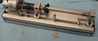
- Collected!
Of course, after each point there are long fittings, adjustments and reflections.
Ready!
Did I get what I wanted? Definitely, yes! Although this is more likely not a body, but a lot of manual labor to have fun during quarantine. And the body itself...
- The minimum size is more like “yes”. You can steal a couple more millimeters here and there and that’s it. We are limited by the size of the board
- Any MATH board - YES
- Any video card (even 3090) - YES
- Any CPU cooling - tower up to 20cm (mugen max) - YES
- Any regular power supply (except modular ones, since they are 2cm deeper)
- Good cooling. 300-350 watts (Ryzen 5600x + 1080ti strix + PSU 700W 90%+) works stably with holes only in the front and rear walls. If it gets hotter in the summer, I’ll widen the holes for the rear fan (you can cut a circle and install a chrome grille). Maybe I'll add holes on the side cover
- A photo of the bottom of the case explains how the power supply is attached and where the air goes from it. Part comes out through the 4 front holes, and part goes under the board tray to the back wall.
Test batch
A test batch differs from a serial batch, firstly, in its circulation: as a rule, this is only a few products. Secondly, another, less widespread technology. And that’s exactly why each copy from the test batch is “golden”. Habré even suggested the term golden sample - it fully reflects the essence. Let's figure out how to organize all this.
6.1. Production
Any production begins with preparation for it. Let's see how this is done (don't forget that our conditional circulation is two dozen cases). As a production technology, we will take polyurethane casting into a silicone mold.
Search for production
Searching for production is no different from choosing any other contractor.
With the exception of the budget, a large plant is absolutely not interested in dealing with a small order. In this case, you need to either be persistent or immediately weed out those who do not make contact. The algorithm is as follows: we are looking for enterprises that use the technology that we need in production, we attach our model in the universal .step (or .iges) format to the application, we write a letter to the factory, where we indicate the circulation, requirements (color, case rigidity, availability inscriptions) and send it to everyone we found. We are waiting for responses. The productions that respond to your letter will definitely ask you clarifying questions. Answer them in detail.
For those who are lazy to look for housing manufacturers on their own, we have created the “Customer” website - zakaz.ist/plast.
Another recommendation is not to pay attention to the geography of the enterprise: there is no point in choosing “closer”. This certainly won’t give you real control over the production process, but it will definitely increase the price. China here is a completely different story, about which volumes could be written.
Production of molds
As I wrote earlier, we will now limit ourselves to a simple example - casting polyurethane into silicone molds.
Other technologies are more complex. When the contract is concluded and the advance portion is paid, the plant begins to produce molds for production. Since we agreed that we need dozens of cases, this means that the mold will be made of silicone, and before that they will make a master model of our case. There are a lot of videos with this process (search for the keyword “casting in silicone molds”) on the Internet, and below is a photo of the mold itself:
They begin to produce test cases of cases using such equipment - to understand how satisfied you are with the resulting case. If you are not satisfied, then you need to make changes either to the case model, and then start the entire development process over again, or limit yourself to a “cosmetic” alteration. The number of changes and the extent of changes is difficult to guess; guarantees are also impossible to achieve; you just need to use common sense and discuss changes with plant specialists.
6.2. Feedback from users
And this is exactly what the test batch is made for - users will tell you things that you won’t be able to figure out on your own.
Conventionally, we assume that the device will be used like this, but for a real user the scenario will turn out completely different; and what kind - you may not even know about it. For clarity, here is an example. A couple of years after the product went into production, it turned out that users were forced to regularly open the device’s case. And the design of the fasteners and latches was made taking into account the opposite scenario - hang it and forget it. And if a test batch had been made and decisions had been made with an eye to testing not only the prototype, but also this batch, then the problem would not have come to light at all. But there was no test batch, and users are still breaking the case (more details - formlab.ru/alarm_system_pritok).
You definitely need to not only listen to what they say (because everyone lies and doesn’t say anything), but also try to understand what they are silent about (for example, a lot becomes clear by examining the samples, if you see chips on the case, scratches from a screwdriver, pinched screws, etc. .d.) All this gives a ton of information that will tell about installation and ergonomic problems much better than the user himself - he may not say anything, because he will consider that this is not important for the project: so, nonsense, think about it, it was a little inconvenient crawl with a screwdriver or for a long time I couldn’t get into the screw head because it was hard to see.
Everything collected in this way, including even seemingly small things, must be carefully collected into a single document, the importance of each identified problem or issue must be determined, and the necessary changes must be made to the documentation and models.
6.3. Editing models and documentation
Everything is simple here - adequate production will definitely let you know about errors in your model, which will need to be corrected in accordance with the recommendation given by this production.
However, if they write to you that the model is “low-tech”, but do not specify why, be sure to ask directly what exactly you don’t like. Or contact a third-party designer to check the model and eliminate any shortcomings.
Before choosing a technology, you can still make mistakes - there is an opportunity to return to previous stages, correct, change or test something. But from this point it will become more difficult and much more expensive to win back.
One of the most common problems, for example, when the prototyping stage was not completed (here: formlab.ru/12mln-v-minus is the story of how people burned 12 million rubles in this manner) or at the stage of equipment production, what equipment was not taken into account - minor changes at the time. The latch doesn’t work as long as it should, something crunches during assembly, or the seam between the body parts is uneven - it’s crazy how expensive it will be to fix all this in production, it’s better to go back a step and double-check.
However, if you have worked well with errors in the previous stages, then there will be no problems with production.
And, of course, a lot depends on the technology you chose for the production of your case: each has a different cost, approach and features.
What didn't work out
- The ease of manufacture is definitely a fail. Bending the corners turned out to be more difficult than expected. Sawing straight is not easy. I had to drill a lot and for a long time.
- 140mm fan. I had to give up for the sake of simplified wiring of the power cable. When using a 140mm fan, you would have to drag 220v from the opposite corner, from the video card. And also, I already had a sensible 120mm.
- The case is rigid and transmits vibration perfectly. It is worth adding soft legs and a vibration-damping gasket at the place where the PB is attached.
- It will probably be a bit hot in the summer and you will have to add holes and rework the back panel
- You can open the side cover until holes are added
What can be done better
- By adding a 5mm gap between the power supply and the front wall, you can install rubber seals and increase the air inlet by a third due to the right holes
- If you remove the middle rod under the mat board, the cross-section of the “air duct” from the power supply to the rear wall will almost double. It is possible to replace the profile with a non-continuous corner.
- The 220V input can be moved towards the video card and the cable can be routed along the rear left edge of the case and along the lower air duct. This will remove the high voltage cable from the case itself and return the ability to install a 140mm fan. You can install a 2-pin power connector (like on printers or household appliances) to reduce the size
- Design a single bent part that combines the motherboard tray, power supply mount and HDD mount
- Definitely laser cutting of all panels. In the prototype, I deliberately went for manual cutting, since the dimensions were unknown in advance.
- Installing a 2.5” drive is possible in the lower air duct (now the front USB cable is installed there) or on the front panel, opposite the video card. Installation of 3.5" drives was not intended.
Design documentation
Examples of design documentation here → formlab.ru/cad.
A package of design documentation is, in fact, a single package of files that should describe your case and all its components in as much detail as possible for production.
Inside there will be (in addition to the three-dimensional models from the previous section) detailed and assembly drawings, specifications (a list of parts with their parameters), a document on the cost of production according to this documentation. All drawings are made, as a rule, in the same CAD in which you developed the models, but I still recommend passing them on to specialists with relevant experience for preparation: you can get seriously burned if you do not notice an error in the design or do not provide the necessary information on the drawing.
4.1. Detailed and assembly drawings
I have heard more than once that drawings are being used less and less in design work. But this is not entirely true - nothing can replace a drawing. The thing is that the drawing describes what cannot be described in the model: tolerances, production accuracy, materials, methods of pairing dependent parts and much more - according to the standards of design documentation. If not according to standards, then different enterprises will have different interpretations of documentation, which means the number of problems during production can increase many times over.
4.2. Specifications
Also an important component of the design documentation package. This is a description of all parts, quantity, material from which the case is made, price (if the component is purchased) and any other important information - all in the form of a single plate, which is filled out at the very end of development and complements the package with drawings and model.
4.3. Cost estimation
It’s a commercial proposal, it’s a quotation, it’s an offer:
And if there is a red seal, then it’s generally good:
Tips for Followers
- The drill stand made it possible to drill all the holes evenly and accurately. If you do it by hand, you need it. I bought it specifically for this case for $30.
- A good ($3.5) 3mm tap is a must have. A special tap for aluminum produced a more “relaxed” thread. I liked the carving more than the usual one for machine cutting.
- The 6-32 (inch) tap is rare and optional. In aluminum, you can easily screw a self-tapping screw from a good case kit into a 3mm hole.
- Avoid using fasteners from cheap housings - there is a high probability of breaking the screw in the hole.
- Bent parts in the body are still needed; without them, it turns out to be Lego from scraps. In my version, these are 3 parts: a power supply mount and 2 corner rings for the rear panel.
- A finished back panel increases the cost of the case and imposes restrictions on the size (although it is beautiful and there is no hassle with bending a corner).
- Not all cutting boards are level. Mine may have started to leak after drilling. There is a curvature of up to 1mm in the middle. When purchasing, check.

- In the factory case, the covers are attached with an overlap and small distortions and cracks are not visible. I had to adjust the covers quite accurately and still, in some places a slight curvature is noticeable
Prototype
In fact, our body has been developed, but it is still a picture on the monitor, a 3D model.
Experience shows that any 3D model has a number of shortcomings that are simply impossible to calculate in a virtual development environment. To identify and eliminate problems, you need a physical model - a prototype of the case. Let's take care of them. To do this, you need to export your model from the source program into a universal format, such as .stl, and send it to a company that does 3D printing. There are a lot of them, the search will help you (and I wouldn’t chase the lowest price tag - it doesn’t end well).
The first question from such a printing company will be: “What technology do you want to use to print your case?”
Case prototype
The question is reasonable: there are already several dozen technologies, and each of them has its own pros and cons. So let's decide: what do we want from the prototype?
- Of course, assemble the device and see what it will look like - i.e. close the issue of collection. At the same time, check whether the device looks as expected.
- I would like to test the device in real life, carry it in my pocket, put it outside in the snow, or dip it in a real puddle to check the tightness.
- Show it to an investor, client, at an exhibition - solve marketing issues, business problems, etc.
Unfortunately, the first generation prototype will not be able to solve all these problems at the same time. On it you can only check the assembly and conditionally evaluate the appearance. “Conditionally” - because the printed model of the case will be far from the real one, mass-produced. But for now this is not necessary.
5.1. Prototype production
For a first-generation prototype (or mock-up), it is better to choose the cheapest technology - plastic filament printing
, or
FDM
. In short, the body will be printed from plastic thread layer by layer from bottom to top, something like this:
Printers that print with plastic filament or FDM technology are now everywhere. All this is inexpensive (a couple of thousand rubles per case, prices hereinafter are relative).
Sometimes it is even advisable to buy a printer and make layouts immediately during development, but this only saves time.
If funds allow, then it is better to order higher-quality printing using SLA or SLS technologies (here the cost will be from 10 thousand rubles). I have already reported on Habré about how to choose the right production technology for a case. And in order not to get up twice, here is my video about “When and why is 3D printing useless?”
Milling of plastic and metal
— the required body or part is milled from a plastic blank, which differs little from the serial product. Such a building will cost from 30 thousand rubles.
Silicone casting
- generally a good option (and the only one if you require a sealed housing or “rubber”, i.e. flexible parts). Such a building will already cost from 50 thousand rubles.
5.2. Assembly and testing
Based on the results of prototyping, you will immediately see where there are problems in the design and design of the case.
Therefore, the next step will be to return to the previous stage and make changes to the model. And so - several times, depending on your accuracy and experience. Experts make do with a couple of generations of prototypes and move on; beginners need more - sometimes even up to dozens. Why is prototyping important? The more prototypes are made, the more problems will be identified, which means the final product will be as thoughtful as possible.
Tests: the device in the housing we developed lay in a bucket of water for a day and then continued to work
5.3. Editing models and documentation
Nobody even thinks about this point at the start, and it’s impossible to avoid changes: always (not even like that - absolutely for all projects) after the testing stage (layout, prototyping), errors are identified that need to be corrected in the model and documentation. And then again and again. Corrections should continue until the team runs out of budget or until it feels like the model is completely polished, the prototype is perfect, and we need to move on to mass production.
Total
The size is good. I was especially pleased with the width - the body turned out to be smaller than the old Aspire X-Qpack. Yes, a little long - 30mm longer, but already 30mm and the same amount lower. Final dimensions Width x Height x Depth: 255 x 210 x 366mm
Without holes on the side wall, the case can be placed on its side - you get a lowered miniTower, just add a bracket so that the video card does not sag. Everything fits. There are reservations regarding power supplies - huge kilowatts and modular power supplies will not be included.
Ventilation between the board tray and the case is an interesting solution. It seems to work and not bad.
Case design development
Industrial designers and designers believe that the design of the case is the main component of a new device, because it is precisely because of it that gadgets are bought.
I saw it, I wanted it, I bought it, I used it. Of course, the engineers and programmers who work on the product's functionality might argue with this. In the process of developing the design and construction of the case, many restrictions are taken into account at once:
- customer wishes;
- purpose of the product;
- area and conditions of application;
- ease of use;
- consumer requests.
At the start, designers work through many options, usually at least 5-7 different directions, from which they select 2-3 of the most interesting ones to demonstrate to the customer or project working group.
As a customer, you may have many ideas that you want to implement in your product, but they cannot always be combined due to technical production limitations or aesthetic contradictions. Experienced designers take into account that discussing and finalizing various cabinet solutions will take about half the time of the entire project. Negotiations, calls, correspondence - personal, together with the designer, with the project manager. Coordination is sometimes more difficult than the design development process itself, but this is a normal part of the project. You need to be prepared for this.
iPhone sketches. Authors: Jonathan Ive and the Apple design team. Date unknown
In parallel (necessarily in parallel!), a designer is involved in the development of the design. It brings the designer's flight of thought down to the real requirements of production technologies. If you leave the designer to his own devices, the development time may be delayed: the design has been developed, agreed upon, re-agreed, super, but it is no longer possible to produce the product by casting in a mold without significant adjustments to the appearance. And you have to start the process again.