The charger for lithium batteries is very similar in structure and principle of operation to the charger for lead-acid batteries. Each lithium battery bank has a higher voltage value. In addition, they are more sensitive to overvoltage and overcharging.
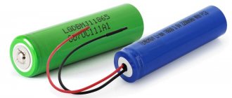
Li-ion battery 18650
The jar is one life-giving element. It got its name from its resemblance to tin cans for drinks. For lithium cells, the most common option is 18650. This number is easy to decipher. The thickness is indicated in millimeters - 18 and height - 65.
If other types of batteries allow you to have a greater variation in the supplied voltage when charging, then for lithium batteries this indicator should be much more accurate. When the battery voltage reaches 4.2 volts, charging should stop; overvoltage is dangerous for them. A deviation from the norm of 0.05 volts is allowed.
The average charge time for lithium batteries is 3 hours. This is an average figure, yet each individual battery has its own value. Their service life depends on the charging quality of lithium batteries.
Long-term storage conditions
Advice. Lithium-ion batteries must be stored correctly. If the device will not be used for a long time, it is better to remove the battery from it.
If a fully charged battery cell is left in storage, it may permanently lose some of its capacity. If a discharged battery is left in storage, it may not recover. This means that even if you try to revive her, you can fail. Therefore, the optimal recommended charge for storing lithium cans is 30-50%.
Powerful battery charger 18650 Aka Kasyan
Lithium-ion batteries of the 18650 size are probably the most popular standard today. They are used in laptops, flashlights, power banks and even in electric cars.
Enthusiasts who decide to build their first electric bike, as a rule, use 18650 format banks as batteries, and not only enthusiasts. Almost all electric bicycles use batteries from these batteries.
Due to the lack of sufficient funds to purchase new batteries, you often have to buy used batteries (used), for example, from laptops. You also have to disassemble them, measure the containers and sort them in order to assemble the battery.
I think everyone knows how to charge an 18650 can. Nowadays you can find a specialized charger.
Or buy a scarf like this, which is powered by a regular USB port and is capable of charging 1 battery with a current of up to 1A.
But what if there are a lot of batteries? That's right, buy more chargers. What if there are too many batteries?
In this case, buying a smart charger is extremely unprofitable. So what to do? It’s natural to take up a soldering iron and find (buy/remake/make) a power supply with a voltage of 5V and use it as much as possible
higher output current.
There is nothing clever in the concept and what is shown here is not new. The author (AKA KASYAN), simply decided to make himself a charger that can simultaneously charge no less than 20 18650 batteries. A good old board based on the TP4056 chip is responsible for charging each bank.
Such boards come with or without protection.
We need those who are without protection. For this project, as you can easily guess, we will need 20 such boards, and another 20 holders for installing batteries.
The author has some charge boards with protection, but he soldered the battery directly to the output of the TP4056 chip, bypassing the protection circuit.
The fact is that, according to the author’s observations, when turned on as standard, the batteries are slightly undercharged, so if you take such boards for a charger, then take those without a protection board. The assembled system naturally heats up, since the TP4056 microcircuits used in this homemade product operate in linear mode, and taking into account the fact that there are as many as 20 of them, the heating is impressive. The power supply itself also gets hot. Of course, it works at maximum power. Now a few words about what the actual feature of such charging is. The fact is that you are unlikely to find a similar unit on sale. The author naturally tried to find something similar, but in online stores he found a charger for a maximum of 8 lithium-ion batteries of size 18650.
From the product description it becomes clear that the maximum value of the charge current, in the case of simultaneous charging of all 8 batteries, does not exceed 500 mA. This is naturally not enough. Having carefully filtered all the offers and compared the prices of the goods offered, the author returned to the initial plan - to do the exercises with his own hands. For safe operation, we will add a fan to the design.
The fan is the most common one, from the most common computer power supply. It is powered by 8 volts, which are obtained using a boost dc-dc converter MT3608, which in turn is powered from the main power supply with a voltage of 5V.
The number of batteries to be charged can be from 1 to 20, since the boards are not connected to each other and each charges its own battery. The holders are the most common. The Chinese have 2 versions of such holders on sale, the author advises using the second option, it costs a little more, but this design is much more reliable and will last much longer.
Well, now let's start assembling.
You can learn more about the assembly process by watching the author’s video:
Inspection and testing:
As you can see, everything works great. The charging process is indicated by a red LED.
Source
Source
Using original chargers
Battery charger
Some manufacturers indicate that using non-original chargers for li ion batteries may void the warranty on the device. The thing is that a bad charger can destroy the battery cell. Lithium batteries can deteriorate due to incorrect voltage or incorrect attenuation at the end of charging. Therefore, using an original charger is always the best choice.
Factory memory
Charging indicator for Li-ion battery.
Hello! With the advent of a cordless tool with Li-ion batteries in my arsenal, a problem was discovered - the absence of a charge indicator. If in an old tool with Ni-Cd batteries this problem was not so acute (it is clear from the loss of power that they were discharged), then with lithium the tool simply stops abruptly. And, which is typical, it is necessary when you are hanging in the most uncomfortable position. Micro review.
The design of the existing tool does not allow pushing the indicator board inside. There is also no room for rechargeable batteries in the form factor of the case. Almost. Having tried dozens of different indicators, nothing good came of it. I decided to order a board of this type. It does not need to be mounted inside the instrument. You can simply glue it to the side wall of the battery case. Ordered on August 26, received on September 16. Fast.
I ordered a pair right away. For two batteries. My batteries are 5S. There is enough space on the side for installation. The back of the indicator is completely flat. You can simply glue it, just make a hole in the housing for the wires.
Board dimensions - 60 mm X 15 mm X 2 mm. On the front there is a film with markings. There are two power wires on the back. Red (+) and black (-).
Under the film inside the indicator. The board is double so that the indicator itself looks flat. Perfect solution.
On the chip I only saw the numbers 324, the letters are hard to see. Similar to the LM 324 op-amp, which is used in such indicator designs.
Sticking an indicator is too easy. I like to get confused. I disassemble the battery, mark the location of the indicator and remove everything unnecessary. The body wall is 1.5 mm thick. Just enough for the fee.
After processing with needle files we get a hole like this.
Because The plastic of the case is viscous, so the indicator is pressed in. Holds on very tightly. You won't be able to push it inside; the batteries are flush against the wall. And on the outside is a sticker with a miracle voltage.
We solder the red wire to (B+) of the balancing board, the black wire to (B-).
Collected. I cut a groove in the sticker so that the indication could be seen (in vain, the sticker is translucent and everything is visible, it was implemented during the installation of the second board).
All five LEDs light up when you press the button when the battery is fully charged.
The indication occurs within 3 seconds on one board and, for some reason, 10 seconds on the other.
I measured the indicator voltage thresholds.
5 diodes are lit - 20.3 V (a fully charged battery showed 20.6 V. In the photo it is slightly lowered) 4 diodes are lit - 19.8 V 3 diodes are lit - 18.9 V 2 diodes are lit - 18.1 V 1 diode is lit - 17.1 V (red)
When the discharge protection is triggered (the tool does not respond), the multimeter shows 10.9 V, the red diode is on.
The second board was installed in the same way. I just didn't cut the sticker. It shines through normally.
I was in a hurry with the first one. Well then.
Finally managed to make a discharge indication. Convenient thing. I hope that I didn’t waste my time on this in vain and that this thing is really needed. All that remains is to find indicators for the 3S batteries of another of my screwdrivers.
Thank you everyone and happy shopping!
Danger of overcharging and complete discharge
Universal charger
Based on the design of lithium batteries, it is not recommended to allow them to be completely discharged or recharged.
For example, nickel-cadmium batteries have a memory effect. This means that incorrect charging mode leads to loss of capacity. The mode is considered incorrect when a battery is recharged that is not completely discharged. If you start charging it when it is not completely discharged, it may lose its capacity. Chargers for such batteries are manufactured with special operating modes that first discharge the battery to the required level, then begin to recharge it.
Lithium batteries do not require such troublesome maintenance. They do not have a memory effect, but they are afraid of complete discharge. Therefore, it is better to recharge them when the opportunity arises, without waiting for a complete discharge. But overcharging is also unacceptable for them. Therefore, it would be optimal not to allow the discharge to fall below 15% and the charge to exceed 90%. This can increase battery life.
This only applies to batteries without protection. If the batteries have protection implemented on a separate board, then it cuts off the charge beyond measure; if the discharge reaches a minimum level, it turns off the device. Usually these are indicators of more than 4.2 Volts and 2.7 Volts, respectively.
Principles of charging lithium-ion batteries
The first thing to note is that a fully charged lithium battery has a nominal open circuit voltage of 3.7 volts. In this case, it must be charged to 4.2 volts. There is no contradiction here - you actually need to charge up to the specified threshold, and after charging is complete, due to self-discharge, the output level will quickly (within a few hours at most) drop to 3.7 volts. After this, the self-discharge process will slow down sharply, and the battery will stably maintain its 3.7 volts.
Unlike many types of batteries, batteries made using Li-ion technology should ideally be charged in two stages:
- charging with a stable current (to maintain it, you need to constantly increase the voltage);
- the second stage is recharging with a stable voltage (the current drops).
Professional memory devices work according to a similar algorithm.
Classic charge graph for lithium-ion batteries.
This and subsequent graphs do not indicate the preliminary stage, which is used for deeply discharged elements. Its meaning is that such a battery reaches its minimum state with a low current, and then the battery is charged as usual.
In practice, the principle of recharging the battery with current pulses of constant amplitude is often used. When a certain cell voltage level is reached (usually 4.15 volts), the charger turns off. The idle voltage of an undercharged battery quickly drops, the charger sees this and again supplies a current pulse until the threshold of 4.15 volts is reached. With each pulse, the battery is recharged, and the decline occurs more and more slowly. Also, the next and subsequent current pulses will be shorter and shorter. Due to this, pseudo-voltage stabilization is realized within certain limits. The advantage of this algorithm is that recharging is impossible in principle , and you can keep the battery in the charger for as long as you like - if it self-discharges, it will be periodically recharged.
Pulse current charging.
Another way to implement the second stage is charging with stepped current. At first glance, this algorithm is complicated.
Charging with step current.
But it can be degenerated to one stage - the voltage supplied to the element simply decreases. The charging current remains stable, although its amplitude decreases. This principle has the right to life in inexpensive chargers. The second stage takes place, in contrast to very simple chargers, in which only the first stage is implemented. Although nothing bad happens in this - the battery capacity is simply not fully used. In addition, there is a widespread but unsubstantiated statement that lithium-ion cells only need to be charged to 90%. No one has provided evidence of this; to believe it or not is everyone’s personal choice.
Charging with single-stage current.
Attitude to temperature changes
Charger for screwdriver
The operating temperature range for lithium batteries is small - from +5 to +25 degrees Celsius. Strong temperature changes are undesirable for their operation.
Homemade charger for lithium-ion batteries
When overcharging, the temperature of the battery may rise, which has a negative effect on its performance. Low temperature also has a negative effect. It has been noted that in cold weather the batteries lose their charge faster and run out, although in warm conditions the device shows a full charge.
Scheme 4 - on a pair of field-effect transistors
In standby mode, it consumes minimal current. Transistors are needed n-channel with a minimum cutoff voltage. When powering the load, a positive voltage is created at the gate of transistor VT1 with the participation of the divider R1-R2. If it exceeds the cutoff voltage of the transistor, it opens, the gate VT2 is attracted to the ground and closes. As the voltage drops, VT1 closes and VT2 opens, allowing the LED to shine. This is a sign that the battery needs to be recharged.
Features of lithium batteries
Li-ion batteries are very unpretentious to use. If handled with care, they will last about 3-4 years. However, it is worth focusing on the fact that even if batteries are not used, they slowly die. Therefore, stocking up on batteries for the device for future use is not entirely reasonable. 2 years is the normal time from the date of production. If more has passed, then these may be already failed batteries.
Interesting. The most common 18650 can size has an average capacity of 3500 mAh. The normal price for such a battery is 3-4 dollars. Therefore, manufacturers who promise a 10,000 mAh Power bank for $3 are, to put it mildly, deceiving. It would be good if there was at least 3000 mAh.
Battery charging chips STBC21 and STw4102
This is a further improvement of the L6924 chip. On the one hand, approximately the same functional package is implemented:
- Linear and quasi-pulse mode.
- Thermistor connected to the battery as a key element of temperature protection.
- Ability to set quantitative parameters for all three phases of the charging process.
Some additional features that were missing in the L6924:
- Reverse polarity protection.
- Short circuit protection.
- A significant difference from the L6924 is the presence of an I2C digital interface for setting parameter values and other settings. As a result, more precise settings of the charging process become possible. The recommended connection diagram for STBC21 is shown in Figure 5. Obviously, in this case, the question of saving board area and strict weight and size characteristics does not arise. But it is also obvious that the use of this microcircuit in small-sized voice recorders, players and simple model mobile phones is not intended. Rather, these are batteries for laptops and similar devices, where replacing the battery is an infrequent procedure, but also not cheap.
Rice. 5. Recommended connection diagram STBC21
ICs STBC21 and STw4102 do not belong to the same family. Although their basic functionality is similar, there are a significant number of differences in the small details. The STw4102 chip, for example, provides greater opportunities for fine-tuning almost all possible parameters; in addition, additional battery monitoring functions are implemented, and it is possible to use an external MOSFET transistor. However, the target application of both chips is approximately the same.
How to make a charger for a lithium battery with your own hands
Homemade charging circuit for lithium batteries
Let's look at one of the simplest charger circuits for lithium-ion batteries. A homemade charging circuit is implemented on a microcircuit that acts as a zener diode and charge controller, and a transistor. The base of the transistor is connected to the control electrode of the microcircuit. Lithium batteries do not like overvoltage, so the output voltage must be set to the recommended voltage of 4.2 V. This can be achieved by adjusting the microcircuit with resistances R3 R4, which have values of 3 kOhm and 2.2 kOhm, respectively. They are connected to the first leg of the microcircuit. The adjustment is set once, and the voltage remains constant.
To be able to adjust the output voltage in place of the resistor R, install a potentiometer. The adjustment must be made without a load, that is, without the battery itself. With its help, you can precisely adjust the output voltage to 4.2 V. Then, instead of the potentiometer, you can install a resistor of the obtained value.
Resistor R4 is used to turn on the base of the transistor. The nominal value of this resistance is 0.22 kOhm. As the battery charges, its voltage will increase. This will cause the control electrode on the transistor to increase the emitter-collector resistance. This, in turn, will reduce the current going to the battery.
You also need to adjust the charging current. To do this, use resistance R1. Without this resistor, the LED will not light up; it is responsible for indicating the charging process. Depending on the required current, a resistor with a nominal value of 3 to 8 ohms is selected.
LED circuit for monitoring the discharge of lithium batteries
It is important to know when the battery runs out. It is not worth discharging lithium batteries to 2.5 V, as there will be difficulties with precharging. The LED's rapid flashing will serve as a visible alarm.
A simple circuit using a voltage monitor is also compact. An undeniable advantage is low energy consumption. This is important when the battery is dead. The flashing LED L-314 will do the job well.
You can buy a ready-made device – MAX9030. The layout diagram is presented. When the voltage drops to 3.0 V, the LED starts to flash brightly at long intervals. In sleep mode, 50 nanoamps are consumed (10-9), with flashes 35 µA.
How to choose a battery
Special attention should be paid to battery manufacturers. There are reputable brands and some unknown analogues. Sometimes unscrupulous manufacturers can sell goods that are 3 times or more lower than the declared characteristics.
Note! Brands that have gained popularity include Panasonic, Sony, Sanyo, Samsung.
Purchasing lithium batteries should not be a big problem. You can buy them at local electronics stores, online stores, or order them directly from China. Don't go after cheap prices. A good battery cannot be very cheap. Some manufacturers supply high-quality banks, but poor boards responsible for power supply. This will inevitably lead to the death of the battery.
The simplest scheme
Today we’ll look at options for a UDB charger for lithium batteries that anyone can replicate. The scheme is the simplest one you can think of.
Products for inventors Link to the store.
Solution
DIY electronics in a Chinese store.
This is a hybrid circuit where there is voltage stabilization and battery charging current limitation.
