A friend and I once went shopping, nothing foreshadowed trouble... We were looking for either a seal for his viburnum, or some other small thing. I suddenly remembered how I recently watched the guys install pneumatic horns, and they sound decent! I wanted the same one for myself, because the standard signal is quiet and inconspicuous anyway. I decided to ask, one elderly man brought me to his stall and showed me a huge selection of beeps. Of these, I liked this one the most.
I couldn’t find any clear instructions, many of the manuals just contain a couple of photos and diagrams, so I decided to write in detail how I did it myself. I hope this post will be useful to someone who doesn’t know much about it and wants to stage it.
The kit included the pipe itself, a hose and a small compressor. No papers, nothing went through. There was no doubt that it was made in China, but the price was reasonable, and so was the quality (nothing fell apart during assembly and works fine). Having looked at the drive, and surfing the Internet anyway, I came across 2 types of connection - through a relay and from a standard bell. At first I didn’t want to do it through a relay - it was too complicated, but I decided to do it anyway. I bought a holder with a 30A fuse, found 2 meters of copper wire, gathered my courage and started assembling it. I found several relay diagrams, here are some of them:
One of the horn options is a pneumatic signal on a car, which has both its pros and cons. Previously very common, it is much less common on modern machines. However, many car enthusiasts still want to install such a device for themselves. You will learn how to do this and much more about pneumatic signals in the article.
Characteristics of the pneumatic signal
Before moving on to how to make this device with your own hands, you need to understand what a pneumatic signal is. And also, what is its operating principle, what are its functions, design. And of course, the pros and cons of having such a horn on board your car.
Working principle and functions
The operating principle of the device is quite simple. Pressurized air from the compressor moves through the tube. This causes it to vibrate and make sounds of a certain frequency. Due to the certain complexity of the design, the cost of such a device is quite high . If you decide to assemble and install it yourself, you will save some money, but the costs will still be significant.
There are signals with different pipe shapes, as well as signal power, which can reach up to 125 dB (video author - Varan Varan).
Design
This device consists of the compressor itself and a tube. The number of the latter can reach up to three. The increased number of horns allows you to achieve a richer and more powerful sound. However, even with one tube, the pneumatic type signal makes a powerful impression. The design also includes a solenoid valve, a check valve, a pressure switch and a receiver.
How to make a pneumatic signal louder
The old signal was broken and worked sometimes after rain) It was decided to take a new one, the old ones were some kind of Russian, they were not very loud.
I’m also bullied by idiots who don’t use turn signals, and I was very nervous when my signal failed every other time! With such a signal, I can now take my breath away and not be so nervous on the road.
Since childhood I dreamed of a loud signal and today I took the plunge and bought a pneumatic signal! I walked around half the market, there was one crap, since there was no choice, I had to take crap, it feels like these signals are collected by narrow-eyed disabled abreks, everything is very clumsy, half is made of plastic, especially the fastenings to the body... But nothing, I took this signal for 200 UAH
I bought this crap:
The pneumatic signal kit included only iron bolts and nuts.
I read a lot about pneumatic signals and people wrote that it is advisable to put the plus signal directly from the battery through a relay. So the signal, in theory, will be louder and there will be no load on the standard wiring.
I used this scheme:
Therefore, heat shrink, terminals, wires and a 5-pin relay were found in the garage, but a 4-pin relay could also be used.
I did everything wisely so that it would last a long time:
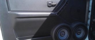
I secured the hoses with plastic clamps, since due to weather conditions they will deteriorate and may become detached:
I put everything in place, thought for a long time about what and how to attach it, it was decided to do it like this: Be careful! The compressor must only be hung in a vertical position!
This way it will last longer and will not dull as much at sub-zero temperatures.
I hid all the wiring under the corrugation so that it would not dangle and would not be visible.
Earlier I wrote that I connected the signal to the standard wires. But this way the compressor did not develop full power, and this was not correct... And then the pipe began to wheeze when pressed, apparently it was clogged. I decided to clean it and redo it the other way, through a relay.
So, let's remove the bumper. And immediately there was a jamb: I broke the fog light bulb and the mounts for the light bulbs.
Okay, let's glue the pieces with two-component glue. Looking ahead, I will say that everything is holding up.
We remove the forge, disassemble it, clean it. We see a lot of oxides, and no appearance at all. Okay, the main thing is that it works.
As it turned out, a small hole (in the area of the red circle) was clogged:
Do-it-yourself powerful steamship whistle. You can assemble interesting crafts from various plumbing components. For example, a steamship whistle (typhon in English). Moreover, to make a cool signal you don’t need to weld, solder or glue anything. Read and see below about how to make a beep - a typhon with your own hands. The money spent will be repaid by the results obtained. It is impossible to buy such a beep anywhere - you can only make it yourself. A diagram of how to assemble a steamship whistle with your own hands is shown.
Accessories
The following parts were purchased from a plumbing store:
1. Bend 40 mm - 90° - 4 pieces;
2. Siphon for sink included - 1 piece;
3. Transition 50 mm - 40 mm - 1 piece;
4. Bend 110mm - 87° - 1 piece;
5. Transition 110 mm - 50 mm.
Refinement of the siphon
Before assembling the structure, it is necessary to modify the siphon; this modification must be taken seriously. Strictly adhere to the proposed revision scheme. You need to shorten the central pipe of the siphon with your own hands so that it protrudes above the plane of the outer pipe by 1.5-2 mm. Using a ruler, we mark the place of the cut and use a metal saw to cut off the excess part. We carefully sand the cut area with emery cloths to reduce the grain size. You should get a smooth, even surface - this is a must.
Siphon Inner pipe Pipe cut Edge smoothed
Difficulties in manufacturing were caused by the method of attaching the rubber sound membrane. There are two ways to implement this. The first way is simple, attach the membrane to the surface of the siphon without further modification of the latter. The second way is complicated, modify the siphon and install a protective cap over the membrane.
The first path was used when constructing the device. If you stretch the rubber and hold it tightly against the outer casing, you can blow into the side hole with your mouth and get a sound. So all available rubber materials were tested; the best effect was obtained from a piece of rubber from a torn swimming cap. There was no denser material at hand. When used permanently, the membrane can be secured with twine and electrical tape. The disadvantage of the first way is that part of the sound will be radiated outward bypassing the output pipe and the membrane may be damaged.
Second way . Various siphons and fastening methods were used, but it was not the original method that won. To avoid premature rupture of the membrane, the external thread on the siphon is completely cut off. The thread on the cap is covered with tape. There are holes cut in the cap itself; the size and number of holes affects the frequency and volume of the sound, and for denser rubber the number of holes may be small. The cap without a membrane should be freely removed from the siphon. See photo.
Thread cut Cap Holes in cap
Making a pneumatic signal with your own hands
You will definitely need to purchase the following items to create a pneumatic signal with your own hands:
- Compressor. Most car enthusiasts in Russia and neighboring countries use products under the Berkut brand. It has several models, the power of the R15 will be enough for you.
- Solenoid valve . With its help, air is discharged from the receiver into the pipes. It can come with them. For convenience, we recommend purchasing these. However, you can buy the valve separately - then pay attention to the voltage and diameter.
- Check valve. It is installed at the outlet of the compressor and should not allow air to flow back from the receiver.
- Pressure switch . Used for this. So that the compressor turns off when the required pressure is reached and turns on again when it drops.
- Receiver. A 4-liter model with a pressure of 12.5 bar is suitable. It should have two holes - one for connecting the compressor and blower, the other for draining condensate.
- Pipes.
Also useful are pneumatic connectors (according to the thread size and the size of the holes of the receiver, compressor and pipe) and fittings.
Pneumatic sound signal for cars
Materials and tools used by the author:
List of materials:
– electric pneumatic valve 12V; – electric pressure sensor (which controls the compressor); – emergency valve for releasing excess pressure; – pressure gauge; – corners and tubes for plumbing; – fum tape; – 12V car compressor; – two fire extinguisher housings; – pneumatic signal (horn); – iron plates; – wires, clamps, hoses, etc.
Homemade manufacturing process:
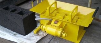
Step one. Receiver assembly
First of all, we will make a receiver; it will accumulate air under a certain pressure to power the sound signal. The author used two fire extinguisher bodies, since one container was too small. We bleed off the gas, unscrew the valve and pour out the powder.
Next, instead of valves, we wrap the tubes and use the corners to connect the two fire extinguishers into a single container.
Step two. Equipment
You need to install the necessary equipment on the receiver; to install the pressure gauge, sensor and emergency valve, the author made a “tee” from the valve body from a fire extinguisher. We simply drill the required number of holes in the copper body and cut the thread. It will be convenient to adjust the signal using the pressure gauge.
An electronic sensor is needed to turn the compressor on and off depending on the pressure in the receiver; it has a corresponding adjustment.
At the other end, at the outlet of the receiver, an electric pneumatic valve for 12V and a tap are installed. When turned on from the passenger compartment, the valve opens and releases air from the receiver, which enters the horn. The tap is needed to regulate the volume of air and, as a result, the volume of the forge.
Step four. Tests
The homemade product is ready, you can test it. As an experiment, the author installed a signal on a scooter. We start the device, the compressor will take some time to pump air into the receiver.
Well, then you can signal, the homemade product turned out to be quite interesting. The sound volume of the horn was about 128 dB, but the power of the device is enough for a louder horn to operate.
At this point the project can be considered successfully completed, I hope you liked the homemade product and found useful ideas for yourself. Good luck and creative inspiration if you decide to do this again. Don't forget to share your ideas and crafts with us!
Instructions for installing an alarm device
Installing this system on your car is carried out in several basic steps.
- First you need to find a place for the compressor. This may not be so simple. Most cars have a space under the bumper where you can place it.
- Remove the compressor from the frame, it is not needed and interferes with installation.
- The pipes can be installed on the radiator cooling system. They and other elements should not interfere with the heat transfer of all elements of the car.
- Now lay the pipes, fittings and valves. To connect the threads of pneumatic tubes, you can use FUM tape.
- Take the wires from the standard power button into the interior.
- Now you need to connect the system to the battery. It is best to do this through an additional relay, so that power is supplied only after the car is ignited.
- Lay air lines up to the air signal.
- You can make a connection through a relay, which will close the contacts of the system toggle switch and control it. It will also be activated from the standard button on the steering wheel.
- Before assembling the car body, check how everything works. Place the air intake fittings higher in the engine compartment. Check how the pressure is maintained.
Removing the Frame from the Compressor
Remember that you can always remove the air hose. It is long enough that you can use it to inflate the tires of any wheel. This is an additional advantage of installing such a signal.
Price issue
Lada Priora Sedan › Logbook › Installation of air horn (very detailed + many photos)
A friend and I once went shopping, nothing foreshadowed trouble... We were looking for either a seal for his viburnum, or some other small thing. I suddenly remembered how I recently watched the guys install pneumatic horns, and they sound decent! I wanted the same one for myself, because the standard signal is quiet and inconspicuous anyway. I decided to ask, one elderly man brought me to his stall and showed me a huge selection of beeps. Of these, I liked this one the most.
I couldn’t find any clear instructions, many of the manuals just contain a couple of photos and diagrams, so I decided to write in detail how I did it myself. I hope this post will be useful to someone who doesn’t know much about it and wants to stage it.
And here, by the way, is a new buzzer.
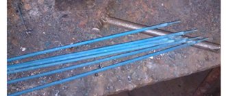
At first I wanted to connect the contacts using construction adapters, I even sharpened and tried them on.
On the other side of the fuse holder I soldered a homemade power terminal made from shelf fasteners using a grinder and a drill =)
Then he wrapped the whole thing with a bunch of electrical tape and put it in a plastic corrugation.
And proceeded to connect the compressor.
Next to the battery I found a place for the relay
Before attaching the compressor, I put cellophane on it from under the pipe, it was already in the morning, because I had been fiddling around for half the night, so it was only in the morning that I realized that like a compressor it would suck air through the cellophane, then I fixed everything and here is the result:
Here is a video of the sound, although it was not possible to convey all the sound, in real life the buzz is louder.
I soldered everything with a regular soldering iron, used solder with rosin and soldering flux (a very good thing!).
In total, all the fun turned out to be 730 rubles. In my opinion they are worth it!
I hope the article turned out to be quite detailed and informative, it will help someone!)
Source
Similar master classes
Do-it-yourself automatic exhaust The most reliable relay for turn signals Has the battery died? A screwdriver will help! The simplest circuit for automatic water level control Do-it-yourself solid-state relay Washing machine malfunction
Particularly interesting
A 100% quick way to obtain seedlings with roots from Effective rooting of a rose using a plastic bottle 3 fresh ideas for the master and do-it-yourselfer 4 signs of how to identify a sweet watermelon 5 fresh ideas for your workshop A way to learn welding without consuming electrodes Comments (2)
Connecting an audio signal via a relay.
I have a 5-pin relay. (Contact 87A - not used)
Automotive relay 12V. Permissible current 30/40A. Relay 5-pin, 12V, 30-40A with mounting plate. Relay is an electrical device (switch) designed to close and open various sections of electrical circuits for given changes in electrical or non-electrical input quantities.
The electromagnetic relay consists of:
Electromagnet (represents an electric wire wound on a coil with a core of magnetic material). Anchors (a plate made of magnetic material that controls contacts through a pusher). Switches (can be making, breaking, switching).
The process of installing a pneumatic signal on a car with your own hands
The pneumatic signal will be installed on a KIA Sorento 3.5. In fact, a set of ready-made solutions from . This way a station capable of delivering up to 7.5 a will be used (BERKUT) SA-03)
Let’s say right away that the use of a more productive station and a station with increased pressure is not justified; for a pneumatic signal, a pressure of 5 atmospheres and an air supply of 2.85 liters, which corresponds to the volume of the station’s receiver, is quite enough. In addition, the BERKUT TG59 installation kit is used, which is actually a set of valves and adapters. An audible pneumatic signal from Cicada was also used during installation. One of the main problems is choosing a place to install the pneumatic compressor, because free space on the car is extremely limited; to understand this, just look into the engine compartment of most modern cars. As a result, the optimal installation option for the compressor turned out to be the space under the bumper.
But first, in order to compactly install the compressor, it must be removed from the frame. In this case, the compressor and receiver can be installed locally.
So, after disassembling the compressor for its further installation, we select only all the essentials that are necessary for the functional operation of our pneumatic signal. The frame on which everything was installed earlier will not be useful to us for installation.
We try on the components of the pneumatic signal. Everything will be pre-installed on the power elements of the “TV”. Here it is necessary to pay attention to the fact that the mounted elements do not interfere with the heat transfer of the radiators of the air conditioner and cooling system.
The air pneumatic signal “pipes” were installed “against the background” of the cooling radiator.
Next, service, control and regulatory equipment is installed. This is how pipelines are laid, fittings and valves are installed. When installing pneumatic pipelines, it is necessary to use FUM tape to connect the threads. This is despite the fact that the threads are, in most cases, conical, and therefore self-sealing. Control wires are routed from the standard system activation button, which will go into the cabin.
Design and principle of operation of an air signal
The first klaxons began to be produced in 1908. Translated from Greek, the word klaxon means “howl.” The first sound signals were a structure that consisted of a plate with a spring secured with a rivet in the middle.
When the gear wheel rotated, it came into contact with a spring plate, and a specific sound was produced. To amplify the sound and direct it in a certain direction, a speaker was installed. Later, a horn appeared in which the gear rotated thanks to electricity.
Thanks to technological progress, signaling devices have improved. A modern sound alarm system includes sound signals (one or more), a switch, a sound signal relay and wires for connection.
- by device: with and without a speaker;
- by sound: tonal and noise;
- according to the principle of operation: pneumonic, electronic and electromagnetic.
Signaling devices receive power from the vehicle's on-board electrical network.
Let's consider the design and principle of operation of signaling devices.
Pneumonic
The principle of operation is similar to the “horns” that were installed on the first cars and horse-drawn carriages. Air is supplied under pressure from the compressor, which moves through a special pipe, creating vibrations and causing it to make specific sounds. Such devices are quite expensive, regardless of the shape and design of the product.
Pneumatic devices differ in signal strength and pipe shape. Their frequency range is created by pipes of different tones. To ensure their sound, it is necessary to install a compressor that can provide a pressure of at least 6-10 atmospheres. The number of horns can be different; the melody of the signal depends on their number. When installing a pneumatic signal on a car, you additionally need to install a relay with a program that will control the opening and closing of the solenoid valves.
Electromagnetic
These devices are based on an electromagnet. It is attached to the main part of the signal - the membrane. The winding of the electromagnet core is connected to the battery through a breaker. The horn is connected to the vehicle ground using a button. When the driver presses the signal button, the core rod begins to move, causing the membrane to vibrate. As a result, a powerful sound is heard (the author of the video is tora 18).
Klaxons of the electromagnetic type differ in the sound emitter:
- Disc (“pancakes”). They can be collapsible or non-collapsible. The second type is more compact and therefore takes up less space in the car. In addition, disk signals can be closed or open. Disc horns are installed either under the hood or in plain sight. It is possible to install several beeps of different frequencies and tones.
- "Snails" These devices are difficult to install because the bell is curved and must be pointed with the open end facing forward. The signal power is very high. They make a sound so loud that it puts pressure on the eardrums. The beeps are produced in two-tone mode, but you can install a relay, thanks to which the voltage will be supplied to the windings alternately, as a result the specified melody will sound.
- "Horns". The bell of these horns resembles a “straightened snail” in shape and looks like a bugle or trumpet. They produce worse sound, but are more convenient to place under the hood.
Advantages and disadvantages of a pneumatic signal
We have already listed the advantages of pneumatic signals, but it is not difficult for us to repeat them. A very loud sound level will allow you to become “noticeable” among other motorists on the road, which can prevent an accident. In addition to the pneumatic signal, you also get a standard compressor on the body of your car, which is also not bad at all. The disadvantages of a pneumatic signal include the high cost of the equipment, as well as the complexity of its connection. In addition, working with pneumatics requires high tightness of the connections, otherwise the compressor will be turned on from time to time to pump into the receiver. Such inclusions can significantly drain your battery, especially during long-term parking. In this case, it is better to connect power to the system through a relay that turns on when power appears in the ignition system circuit. In any case, the tightness of such a system will be lost much earlier than the functionality of the standard signal, which will lead to the need to replace the sealing elements and valves in it. That is, we can say about more expensive maintenance. In any case, weighing all the pros and cons and making a choice based on what is a priority for you is only your prerogative.
Making a 12 Volt air horn for a car with your own hands: from theory to practice
An air horn on a car serves to attract the attention of road users, especially pedestrians. If the standard signal is not satisfactory, you can replace it or install an additional one. The article discusses the device, the operating principle of the signaling device, and also gives instructions on how to make a 12 Volt air signal for a car with your own hands.
Tuning VAZ 2109
- signals from the Volga with a “mass” on the body
- relay type 90.3747 with mounting flange
- relay socket
- female terminals wide
- heat-shrinkable tube (HERE)
- stranded wire with a cross section of 2.5 mm. sq.
- blade fuse block
- 20 A fuse
- metal corner
Spare parts for modification
First of all, remove the ground terminal from the battery.
To access the standard signal of the VAZ 2109, remove the radiator grille, unscrew the standard signal along with its fastening bar. The signal ground wire is attached nearby, we dismantle it too.
At home, we will first prepare the mounting of signals from the Volga based on a steel angle purchased at any building materials store. We will attach the signals to the standard place where the original signal is attached. We mark the corner at the installation location, saw it off, and drill holes for attaching signals from the Volga. It is also advisable to paint the corner to protect it from corrosion. Next, we attach the signals to the corner. The signal fastening bolt is also a “ground”, so it is necessary to ensure its electrical contact with the angle, for example, by securing the Volgov signals through a castle washer.
We fasten the corner with the signals to the bolt securing the standard Samara signal through a castle washer to ensure contact of the corner with the ground. It is possible that the bolts securing the Volgov signals on the corner will touch the radiator; in this case, we put washers, thereby moving the corner with the signals away from the radiator. Do not forget about the need to preserve the corner with the car body (“ground”). That's it, the mechanical part is over, let's move on to the electrical part.
Signals from the Volga to the VAZ 2109 are connected according to the following scheme:
Electrical diagram for connecting Volgov signals to Lada Samara
We crimp the ends of the wires with appropriate terminals. We hide all connections in a heat-shrinkable tube.
The relay can be mounted on the back of the radiator frame, next to the headlight.