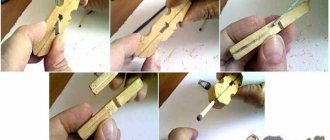
One of the many machines, in the general sense of the word, is a photo relay. It is visually invisible, has little functionality and is used in many niches. The device has a single reaction to the external factor of the presence or absence of light - the connection or break of the line through which the current flows. The latter is used both directly to disconnect or activate consumers, and as a signal pulse. You can meet photo relays in many areas of life, from production control lines or subway turnstiles, to their presence as elements of various types of lighting switches.
Turnstiles in the metro:
Many people have more than once found themselves in situations where the location of objects cannot be seen in the dark. Moreover, this interferes not only with the process of personal movement, but also creates inconvenience when you need to find something in the dark. The issue can be completely resolved by installing a lamp. But the problem with turning it on in the dark immediately becomes apparent. Here, a photo relay can be used as an automatic machine, turning on the lighting precisely at those moments when darkness sets in.
The mentioned niche of use is not the only one. Based on the sensor’s response to visible radiation, both devices that count units of goods and security devices are built. Both of these types determine the intersection of a ray of light with an object. Systems for automatically opening doors, gates or barriers are made on the same principle.
The simplicity of the design makes it easy to make a complex from a reacting part and a photo relay with your own hands, which will be discussed in the article. Types of connections of ready-made assemblies produced by industry and their circuits will be considered, revealing the essence of these parts, from the most basic to those based on a microcontroller.
Scheme of a simple photo relay
Let's start with a simple device like a night light. When it is light, it is off, but the darker it gets, the brighter the lamp burns. Just a quick reminder - the device is powered by 220 V, so you need to be careful and attentive when assembling and checking it.
Night light diagram:
The lower the illumination of the photoresistor, the more open the seven-storage switch Q6004LT is. Accordingly, more current is supplied to the load, which is a low-power incandescent lamp.
There is a variant of the described scheme that already uses 5 elements. In it, the lamp simply lights up in the dark at maximum brightness and goes out when light hits the photoresistor.
A simple photo relay circuit:
The sensitivity is adjusted by selecting the value of R1. It needs to be changed in any direction within relatively small limits. The resistor power is chosen to be 1 W in all cases. The KU208G semisistor can be replaced with a KU601G without losing the functionality of the final device, but in any case, a heat sink must be installed on the said circuit element - when using the specified load, it gets very hot.
Another simple design is the use of a photo relay in conjunction with several transistors. The above diagram was initially designed to connect consumers through the opening line of the electromagnetic relay.
Transistor photo relay:
Photoresistor PR1 with trimmer R1 act as a voltage divider that controls the state of transistor VT1, which in turn opens or closes VT2. The latter passes current to relay K1, which opens or connects the load power line. Diode VD1 shunts current surges when the electromagnetic element is triggered, protecting the transistors.
Note! The specified device is no longer powered from a 220 V network, but has its own current input from 5 to 15 V. As for the functions of the R1 trimmer, it is needed to set the sensitivity to the flow of light, which leads to the operation of the device itself.
Selecting device parameters
Before you buy a photo relay, you need to determine the technical characteristics of the device:
What voltage is it designed for? In most cases, this is 220 volts; imported models may have a requirement for 110 or 127 V. There are 12 and 24 V devices (to connect these to a regular network, you will need a power supply). Look at the panel to find out your network voltage. Maximum load current value. Most often, this parameter has a range from 5 to 16 A. It is selected based on the number and power of light sources connected through a photo relay. Sensor response range. In the standard version, the devices have limits from 5 to 50 Lux (lux is a unit of illumination measurement). More expensive models have more precise adjustment. Device power consumption at rest (from 0.1 to 1 W) and when triggered (from 2 to 10 W). Time interval (from 15 to 30 sec.) in case of accidental darkening of the photocell. Keeping the sensor briefly exposed to strong shadows or headlights will prevent false alarms. The degree of protection of the device body from external factors. For street lighting, they usually choose the index IP 65 or IP 44; the IP 40 marking indicates that the photo relay can be used outdoors only with a protective casing. The maximum permissible outside air temperature for normal operation of the photo relay, this range is from -20 to +50 ⁰С. The dimensions of the device are selected depending on the location of the device, the dimensions of the shield
Whether a compact external part is needed or this is not so important, everything is selected individually.
Repeatable industrial option
As a kind of standard, consider the FR-602 photo relay circuit from the EIK company. Most of the similar devices on the market are structurally similar, differing only in small details.
Appearance:
Schematic diagram of a photo relay along with a printed circuit board:
As you can see, the design is simple and can be done at home. Elementary base:
| Designation on the diagram | Model/type | Characteristics | Analogs |
| C2 | Capacitor | 0.7uF, 400V | |
| C4 | Electrolytic capacitor | 100 µF, 50 V | |
| C5 | 47 µF 25 V | ||
| R2 | Resistor | 1.5 MOhm, 0.125 W | |
| R3 | 220 Ohm, 2 W | ||
| R4 | 1 MOhm, 0.125 W | ||
| R5 | 560 kOhm, 0.125 W | ||
| R6 | 200 kOhm, 0.125 W | ||
| R7 | 100 kOhm, 0.125 W | ||
| R8 | 75 kOhm, 0.125 W | ||
| R9 | 33 kOhm, 0.125 W | ||
| W.L. | Construction resistor | 2.2 mOhm | |
| ZD1 | Zener diode 1N4749 | 24 V | 3 series-connected D814A, or 2 D814D |
| D1-D5 | Rectifier diode 1N4007 | ||
| VD1 | Rectifier diode 1N4148 | ||
| Q1, Q2 | Bipolar transistor BC857A | KT3107B | |
| PH | Photocell (photoresistor) | Up to 110 kOhm | |
| Rel | Relay SHA-24VDC-SA (Rel1) |
DIY outdoor LED floodlight installation
LED floodlights for illuminating suburban areas have become very popular today. They are economical, provide a powerful, bright beam of light, and perfectly illuminate a certain area. For more efficient use, motion or light level sensors are additionally installed, which automatically turn on the lamps when moving or when it gets dark. You can choose and purchase high-quality and inexpensive LED spotlights here.
One of the advantages of LED street lights is the simplest installation, which you can do yourself
Site selection When planning installation, careful attention should be paid to site selection. According to accepted safety standards, street floodlights can be mounted at some distance from flammable materials and surfaces
High-power lamps must be installed so that there is an air gap between the housing and the wall. Additionally, you can protect the surface (especially wood) with a sheet of tin. When using light and motion sensors, care should be taken that they are not obscured, otherwise they simply will not work. The position of the future spotlight depends on the requirements for illumination and the direction of the light beam: • car parks and areas in front of the house are illuminated by lamps, the light from which is directed vertically downwards; • gates near the garage or fence are illuminated by spotlights, the beam of light of which is directed horizontally; • for paths, lawns, and facade walls, you can use lamps whose luminous flux is directed strictly upward.
The procedure for installing an LED spotlight The procedure for installing an LED spotlight on the street with your own hands includes the following steps: • a cable is pulled to the installation site, observing all safety standards and regulations (it is best to use a multi-core copper cable); • the lamp is applied to the selected place, with a simple pencil you should carefully mark the fastening points on the surface, check their horizontalness with a building level; • the spotlight is screwed on with self-tapping screws, the type of which depends on the surface material (wood or metal); • when fastening to a concrete wall, you must first drill holes for dowels or metal anchors with a hammer drill; • the spotlight is firmly mounted on the wall; it should not move or wobble easily.
The next step is to connect the lamp to the electrical network: • the line is de-energized; using an indicator screwdriver, you should additionally check that there is no phase on the cable (all measures should be taken to ensure that it does not appear accidentally); • the lamp contact box opens (it is located outside or inside the spotlight body, which depends on its model); • the power cable is inserted through a small hole (it has a special seal that protects the box from moisture); • power wires are connected to the terminal block (black or blue wire goes to zero, yellow or green goes to ground, brown or red goes to phase); • the box cover is put in place, all screws are tightened, after which it is necessary to check the installation of all seals; • the lamp is put in place, electricity is connected; • The spotlight can be turned on to check that the work has been done correctly.
Attention: When checking the performance of the spotlight, you should remember that it does not cool down immediately after turning off, remaining very hot for some time! If you purchased a 12 V spotlight, a mandatory connection element is a separate power supply or transformer, which is not required if you use conventional energy-saving lamps. A large selection of which is here https://salonlustr.com.ua/c9_14-Lampi_energosberegayushchie
Outdoor LED floodlights can be mounted in any convenient place. To save energy, it is best to immediately provide a special motion sensor that turns on the lamp if any moving person or object enters its field of view. Such sensors can be equipped with light indicators that turn off lamps during daylight hours.
WE RECOMMEND READING
- 08/04/2016Which lighting to choose for a nursery
- 09.29.2014Installation of electrical wiring in a wooden house
- 11/24/2014 Faceted metal support for lighting
- 11/24/2014 We understand electric household boilers
Connection diagram of classic photo relays to the consumption line
All types of commercially produced or self-made relays require separate power. Accordingly, two contacts of the device will be intended for the named purposes. Moreover, there are photo relay models without a built-in voltage converter, which means that power is supplied to them not from a 220 V network, but through a separate step-down unit. There may be several lines going to consumers, depending on the number of internal electromagnetic switches. Moreover, the input can be separate for each contact, combined among others, or even integrated with the power supply of the photo relay itself.
The light sensor in most models is built into the body of the device itself, but there are also separate options that allow you to move it away from the device itself. The latter is necessary in cases where the photodetector is not illuminated by controlled lamps, so that the system does not turn into a strobe. That is, when it is dark, the device turns on the lamps. It becomes light - he turns them off. Again it triggers darkness. And so on in a circle.
Single
The previously described model FR-602 and similar ones are connected to the line as follows:
For a large number of energy consumers
To control a powerful load, for example, when connecting a spotlight or numerous lamps, it is better to use intermediate relays. In the role of the latter, appropriate devices are selected that can withstand the passage of a large current sufficient for power supply. An example would be RK-1p/2p (Un), MRP-2, IEK ORM-41F-1, DEKraft PR-102 and the like. Please note that some of the relays of a similar design are designed to control alternating current (AC), while others are designed to control direct current (DC). In addition, the switching voltage may differ to the lower side from the socket rating. The last two factors are important to consider when designing a wiring diagram. If the intermediary relay is powered by direct current, then the photo relay must control the supply of electricity to the conversion unit. Which, once turned on, will activate the electromagnetic contactor, activating the main power line of client devices.
Using other photo relay models
Here is a diagram for connecting a photo relay for another version of the finite state machine - with an external light sensitivity sensor and separate contact lines. Initially it was prepared for FR-7E, but is also suitable for similar models from other manufacturers.
Photo of FR-07E:
Please note that the presented photo relay and the one mentioned earlier differ in the housing, and in particular in the protection of the device from external factors. The FR-601/602 can be safely placed outdoors on the street, while the FR-7E requires the installation of an additional casing for a similar effect. But devices of a similar installation plan are produced with all the necessary fastenings in a standard electrical panel, including prepared mounting locations for the DIN rail.
Where to put
The installation location is selected so that the photocell is not exposed to light from a lamp, window, or advertising board. When the house is located near the roadway, the light from the lights of passing cars should not be directed at the device. The choice of location is limited by height requirements - 1.8-2 meters from the ground (if installed higher, a stool/chair or ladder/step-ladder will be required for adjustment).
Solving this problem is made easier by using some tricks. The photo sensor can be protected with a piece of black plastic pipe of the appropriate diameter, 15-20 cm long. The cutting angle is 30-45° from the pillar or wall. If there is only one spotlight, the photo relay is placed on the other side of the pole. The parameters are adjusted more accurately if the sensor is placed on the west or east side.
Expansion of functionality with the addition of a time relay
When planning to use a photo relay for street lighting with your own hands, you can slightly expand its functionality by adding a timer that turns off the light after a set time. The reason is simple - you don’t need to waste electricity running lamps all night when no one really needs them. For implementation purposes, you can use a shutdown relay, like IEK ORT-A2-AC230V, THC-B1 or similar.
Extended power supply circuit for street lighting:
Purpose
This device is designed to turn on the lighting when it gets dark and turn it off when dawn comes. When assembling with your own hands, the photo relay circuit must include a phototransistor or photoresistor, which change their parameters with the dynamics of illumination. The power circuit is open as long as the required amount of light reaches these devices. As soon as darkness sets in (its parameters can be set), the circuit closes. When morning comes, the process goes in the opposite direction.
Microprocessor photo relay
Modern technologies have also affected photo relays. Devices based on microcontrollers are increasingly being used, which allow not only determining the presence of light flux, but also combining many other functions. Moreover, the expansion does not require significant changes in the hardware component; it is enough to modify the internal program.
A microcontroller is a small computer, initially focused on controlling devices depending on external factors and an algorithm. In addition, its capabilities are quite sufficient for joining a common digital network that unites groups of equipment of various types.
It is also worth mentioning industrial samples of photo relays equipped with a “smart” part. But their functionality is usually limited by the manufacturer. Therefore, it is better to consider another system. For example, Arduino. Its capabilities are quite sufficient to control the light, turn off the line day and night, send messages about the current mode in use or signal problems in the performance of the lamp.
On the hardware side, everything that does not directly relate to the control functions is assigned to additionally connected “shields” to the Arduino. In the above diagram, the latter will refer to the clock, the light sensor and the relay itself. The issue of sending the status to the final owner is resolved using the GSM communication module, which will send SMS about the current operating mode of the system.
The design concept is quite simple:
There is a note regarding the assembly shown. Please note that the relay module has external power supply. This is done in order to avoid current surges, since the shield takes a lot of electricity from the common line and can cause a voltage “dip” during switching. Separate power supply is also recommended for SIM800L (in the diagram above it is connected directly to the Arduino itself). Also, the GSM communication module is quite a consuming element - it needs to generate a certain power to connect to a cell tower, and it can only take energy for this purpose from the supply line.
As for the software part, anyone familiar with programming Arduino microcontrollers can write the appropriate algorithm. Moreover, there are many codes on the Internet.
Despite the functional simplicity of the photo relay, it has enough niches for application. Moreover, small capabilities are expanded by adding new ones due to slight complication of the circuit and the use of microcontrollers.
Step-by-step installation instructions
Right away I would like to move a little away from the topic and advise you to simultaneously connect a photo relay and a motion sensor for lighting. When paired, these two devices will allow you to turn on the lamp when darkness falls, only if a person appears in the detection zone. If there is no one on the site, the lights will not light up, which will significantly save energy.
The installation method depends on what protection class and type of mounting of the twilight light switch you purchased.
Today there are various manufacturing options, namely:
- with mounting on a DIN rail, on a wall or on a horizontal surface;
- outdoor or indoor use (depending on IP protection class);
- photocell built-in or external.
In the instructions, we will provide an example of installing a photo relay for street lighting with wall mounting. The connection is made at the stand for convenience, especially since this is just an example.
So, in order to connect the photo relay to the lamp yourself, you must complete the following steps:
- We turn off the power at the input panel and check the presence of current in the distribution box from which we will run the wire.
- We stretch the power wire to the installation site of the photo relay (next to the lighting fixture). We recommend that you use a three-core PVS wire to connect the twilight switch, which has proven itself to be a reliable and not too expensive conductor option.
- We strip the conductors of insulation by 10-12 mm in order to connect them to the terminals.
- We create holes in the housing for inserting the cores in order to connect the photo relay to the network and the lamp.
- To increase the tightness of the case, we attach special rubber seals in the cut holes to protect against dust and moisture getting inside. By the way, the twilight switch must be placed in such a way that the inlet holes are at the bottom, which will prevent moisture from penetrating under the cover.
- We connect the photo relay for street lighting according to the electrical diagram that we provided above. As can be seen in the photo, the input phase is connected to connector L, and the input neutral to N. A separate screw terminal with the appropriate designation is provided for grounding.
- We cut off the required length of wire to connect the photo relay to the light bulb (in reality, it could even be an LED spotlight). We also strip the insulation by 10-12 mm and connect it to terminals N' and L', respectively. The second end of the conductor is brought to the light source and connected to the terminals of the socket. If the lamp body does not conduct current, grounding does not need to be connected.
- Installation and connection are completed, let's move on to setting up the photo relay with our own hands. There is nothing complicated here; the kit includes a special black bag, which is necessary to simulate night. On the body of the light sensor you can see a regulator (signed with the abbreviation LUX), which is used to select the light intensity at which the relay will operate. If you want to save energy, set the rotary control to minimum (o). In this case, the signal to turn on will be given when it is completely dark outside. Usually the regulator is located next to the screw terminals, a little to the left and above (as shown in the photo).
- The last step of connecting the photo relay is to attach the protective cover and turn on the power on the panel. Once you do this, you can proceed to testing the device.
That's all I wanted to tell you about how to install and connect a photo relay with your own hands. We also recommend that you watch a visual video lesson, which shows in detail the entire essence of electrical installation.
Instructions for connecting a Feron photo relay
Finally, it should be said about which manufacturers of twilight switches are of the highest quality. Today it is recommended to give preference to products from companies such as Legrand, ABB, Schneider electric and IEK. By the way, the latter company has a fairly reliable model - FR-601, which has many positive reviews on the forums.
Specifications
Supply voltage. Almost all light relays are designed for a supply voltage of 220 V. Sometimes models are sold with power from 12 or 24 V DC or 110 V AC, in which case they must be connected through a step-down transformer.
Load level. This parameter is given for active loads in the form of conventional incandescent lamps; when using fluorescent lighting devices, this parameter is lower. Less commonly, in imported models, instead of load power, the maximum current is indicated.
Operation threshold. It is usually adjustable in a wide range of 2-300 Lux. To save energy, the lowest response threshold is set - 2 Lux, corresponding to the illumination of deep twilight. Cheap photo relays (usually from a Chinese manufacturer) do not have an adjustment of the response threshold; their preset response value is 5-15 Lux.
Delay time. There are situations when a short-term light flux hits the photocell (headlights, lighter, flashlight). To avoid turning on the lights on the entire street, there is a delay in the response time when turning on and off. This value varies between 15-60 seconds; some imported models have a response threshold of 100 seconds.
Power consumption at rest. For standby mode, this value is small and ranges from 0.1-0.5 W.
Degree of protection from moisture and dust. Depends on the modification of the relay; outdoor models that meet international standards must have a protection class of IP44. For modifications with an external photodetector, these parameters are set individually for each part of the device. For a remote sensor, the optimal value of the protection parameter is IP45 or IP44; the electronic unit built into the electrical panel can have a degree of protection IP20.
Temperature Range. Photosensors or external external elements must operate correctly in a temperature range of -20 C - + 50 C; some models from foreign manufacturers produce devices with a wider temperature range of -40 C - +70 C.