01/24/2022 14,738 Light and sound devices
Author: Ivan Baranov
Many car enthusiasts, in order to improve the appearance of their car, tune their “Swallow” with LED lights. One of the tuning options is a running turn signal, which draws the attention of other road users. The article provides instructions for installing and configuring turn signals with running lights.
[Hide]
Assembly instructions
LED lamps are semiconductor elements that glow when exposed to electric current. The main element in them is silicon. Depending on what impurities are used, the color of the light bulbs changes.
Photo gallery “Possible options for dynamic direction indicators”
1. Dynamic direction indicators
2. Dynamic running turn signal
3. LED tail lights
Tools and materials
To make a running turn signal with your own hands, you will need the following tools:
- soldering iron;
- side cutters or pliers;
- soldering iron and soldering material;
- tester.
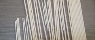
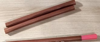
You need to prepare fiberglass laminate from consumables. It is needed for the manufacture of a printed circuit board on which the semiconductor element will be placed. The required LEDs are selected. Depending on the characteristics of the LEDs and the current and voltage values of the on-board network, the characteristics of the protective resistors are calculated. Using calculations, the remaining components of the network are selected (the author of the video is Evgeny Zadvornov).
Work sequence
Before making turn signals, you need to choose a suitable scheme.
Scheme for manufacturing running turn signals
Then, based on the diagram, make a printed circuit board and apply markings on it to place future elements.
The assembly consists of a sequence of actions:
- First, you should turn off the power to the car by disconnecting the negative terminal from the battery.
- Next, you need to remove the old turn signals and carefully disassemble them.
- Old light bulbs should be unscrewed.
- The joints should be cleaned of glue, degreased, washed and allowed to dry.
- In place of each old element, a new running light turn signal is installed.
- Next, assembly and installation of the lights is done in the reverse order.
- After installation, the wires are connected.
At the next stage, an additional stabilized power source is connected to the network. Its input receives power from the intermediate relay, and the output is connected to a diode. It is better to place it in the instrument panel.
When connecting LEDs, you must ensure that the anode is connected to the plus of the power source, and the cathode to the minus. If the connection is not made correctly, the semiconductor elements will not light up and may even burn out.
Flexible LED DRL strips
RunLed - running LED turn signals for cars
How to make a car seat cover with your own hands?
4 stages of manufacturing RunLed - modern running LED turn signal or car stop indicators. Let's consider the principle of installation and operation of RanLed, equipment, characteristics and price. At the end of the article there is a video review of RunLed.
- What is RunLed
- Advantages
- Installation and operation principle
- Price and equipment RunLed
- Video
RunLed – running LED repeaters of vehicle turns and stops. Thanks to this technology, your car will easily stand out from the crowd. Today, this is one of the revolutionary ways to tune a car, without violations or making technical changes to the design. The manufacturer promises not only to highlight your car's style, but also to ensure stable operation of the installed parts.
Unlike car taillights, the new LED-based RunLeds will never fade, do not burn out, and can withstand heavy overloads. According to the manufacturer, the technology can last for hundreds of hours, and the kit includes everything for quick installation; everything will take a maximum of 15 minutes.
Features of installation and configuration of running direction indicators
You can install dynamic turn signals instead of conventional LEDs. To do this, the repeaters are removed from the mirrors, the board with LEDs and current-limiting resistors is dismantled. On the repeater you need to tear the glass away from the body. Then you should carefully cut out the reflector and remove it.
In place of the remote reflector, an SMD 5730 board is installed, on which yellow LEDs are located. Since the repeater has a curved shape, the board will have to be delaminated and bent a little. You need to cut off the part with the connector from the old board and solder it to connect the controller. Then all components are returned to their place.
To adjust the timing of the running LED lights, a switch is soldered to the microcontroller. When a suitable speed is found, jumpers are soldered in place of the switch. When connecting two pins to ground, the minimum time between LED flashes will be 20 ms. When the contacts are closed, this time will be 30 ms.
LED dynamic turn
Price issue
You can make a running light turn signal from daytime running lights. Their cost is 600 rubles. In this case, you can use “pixel” RGB LEDs as light sources in the amount of 7 pieces for each running turn signal. The cost of one element is 19 rubles. To control the LEDs, you need to purchase an Arduino UNO costing 250 rubles. Thus, the total cost will be 1060 rubles.
Loading …
How to make a running “smart” turn signal for a car with your own hands
Instructions for treating the underbody of a car against corrosion with your own hands
- Connection diagram
- Controller firmware
Let's consider creating a running turn signal like on an Audi, using the example of a headlight from a Renault Clio car. Let's make turn signals and DRLs in one device.
What you will need for this:
LED strip consisting of ws2812b LEDs
Arduino nano controller (can be used in any other form factor) Car charger for mobile phones or any voltage converter 12V->5V. Since the LED strip needs a voltage of 5V, we will use this charger as a voltage converter from 12V to 5V. 4 resistors 100 kOhm and 4 resistors 47 kOhm, as a voltage divider.
Connection diagram
The Arduino controller must be connected to the car's network via a 12V -> 5V converter so that the voltage to the circuit comes from turning on the ignition.
The positive wire from the operating turn signals is connected to pins 5 and 6 of the controller through a voltage divider made of resistors. Buttons for additional controller operating modes are connected in a similar way.
Controller firmware
Download a NEW sketch in which the number of diodes varies variably count here.
You can download the finished sketch in a file using this link.
To work with pixel LEDs you will need a library. You can install it as follows: Sketch -> Connect library -> Manage libraries. Next, enter the name of the library Adafruit_NeoPixel.h in the search menu and click the install button.
After that, insert the sketch into the program and replace the number of LEDs in the code (we use 7 diodes):
if (digitalRead(5) == LOW and digitalRead(6) == HIGH) { // one turn signal is turned on for(int k = 0; k
}
} } if (digitalRead(5) == HIGH and digitalRead(6) == LOW) { // turn on the second turn signal for(int k = 0; k
Color(63, 17, 0)); // R=255, G=0, B=0 — LED color strip2.setPixelColor(j, strip2.Color(127, 34, 0)); // R=255, G=0, B=0 — LED color } delay(60); strip2.show(); } } } if (digitalRead(3) == HIGH) { // special signals mode, if we apply a plus to pin 3 for(int j = 0; j
Color(255, 0, 0)); // R=255, G=0, B=0 — LED color strip2.setPixelColor(i, strip2.Color(0, 0, 255)); // R=255, G=0, B=0 — LED color } strip.show(); strip2.show(); delay(20); for(int i = 0; i
Color(0, 0, 0)); // R=255, G=0, B=0 — LED color } strip.show(); strip2.show(); delay(20); } for(int j = 0; j
show(); delay(20); } } if (digitalRead(4) == HIGH) { // Strobe mode, if we supply power to pin 4 for(int j = 0; j
show(); delay(15); for(int i = 0; i
Color(0, 0, 0)); // R=255, G=0, B=0 — LED color strip2.setPixelColor(i, strip2.Color(255, 255, 255)); // R=255, G=0, B=0 — LED color } strip.show(); strip2.show(); delay(15); for(int i = 0; i
}
Video of how our headlight works:
How to install and how RunLed works
As already mentioned, installing the RunLed kit is quite simple; you do not need to be an electrical specialist. By following all the necessary instructions and steps specified in the documentation for the kit, even an inexperienced owner can easily install and configure everything.
Before you start installing RunLed running LED turn signals, you need to decide how and where the set, or more precisely the LED strip, will be installed. The manufacturer recommends hiding it behind body parts so that there is no direct visibility, otherwise there will be a bright and direct glow for drivers behind. The next installation step is to measure the length of the RunLed strip to the length of the mounting area. The tape should not hang down or be longer than the surface. In order to adjust the length, the entire tape is divided into small sectors; all that is necessary is simply to cut off a certain sector with sharp scissors, thereby shortening the tape.
The second step in installing RunLed is surface preparation. According to the seller's recommendation, the surface must be washed, dried and degreased. In addition, it is recommended that there is no rust or chips on the surface, otherwise over time the tape will simply lag behind in this place, and at speed it may become damaged. It is recommended to install the tape near the rear bumper, at the junction of the body and the trunk lid seal. The surface and place of fastening should not be movable, otherwise the wires may break or the tape itself may be damaged. Therefore, it is not recommended to install the RunLed kit on the trunk lid itself.
The process of attaching the RunLed tape is quite simple: degrease the surface and adjust the required length. Before attaching the tape, you need to calculate the center of the tape and the center of the car in width. Due to this calculation, there will be a uniform glow in emergency parking mode; as a rule, the glow comes from the center and to the sides in the form of a creeping line. Having removed the protective surface, due to self-adhesiveness, the RunLed tape must be pressed against the surface and pressed well with your fingers several times.
Connecting the RunLed strip is no more difficult than attaching it. The manufacturer took care of this in advance; the instructions contain all the necessary steps for connecting to the car bus. To protect yourself during connection, it is recommended to remove the terminal from the car battery; if it is not possible to turn off the power to the car, then it is recommended to use tools (pliers, tweezers and electrical tape) to connect. The diagram indicates which wires of the RunLed unit correspond to the functions of the vehicle's rear stops.
If it is still not possible to install it on the lower part of the trunk and the tape can only be installed on the trunk lid, the kit includes a special extension cord for wires from the tape to the power supply. In the diagram, the manufacturer also describes the method of using the extension cord. It is worth understanding that in this case it is necessary to carefully hide all the wires under the casing, and the fastening of the tape itself must be reliable.
From the wiring instructions it follows that the black wire of the RunLed tape is responsible for ground (minus), the red wire for plus (the system is designed for power from 12V). Therefore, you should connect them carefully and best of all to the dimensions, so that during the day you will not waste extra light, and when you turn on the dimensions, you will look more efficient and attractive.
The operating principle of the RanLed set itself is very simple. If connected correctly and the installation follows the diagram, the system will give a unique image to the car. When you turn on one of the turns, the tape begins to display the same effect but with the help of a creeping line in the direction of the turn. Stops can be displayed in several modes, with regular backlighting, a running line, or several other effects at the request of the owner.
The most interesting displays are the emergency parking effects and the usual glow effects. As a rule, they start from the center of the car and diverge to the sides, or they glow in segments in turn. The free display effect can change color, directions, or even be chaotic, without a specific sequence.
Contents and price of the RunLed set
At first glance, it seems that such RanLed LED tuning costs a lot of money, but in fact the price is moderate and affordable to everyone. The RunLed kit includes all the necessary parts and components for proper installation; the manufacturer took care in advance, thinking through every little detail.
The RunLed kit includes:
- multifunctional LED strip;
- Control block;
- installation guide;
- manual.
The manufacturer provides a guarantee for all RunLed parts, and the buyer has the right to refuse the order in the first 14 days without explaining the reason for the return. If one of the elements of the set breaks, the manufacturer undertakes to replace it or return the full cost of the set. In this case, the period for filing an application from the moment of sale to return should not exceed 6 months, and the purchase receipt and packaging must also be kept.
If the RunLed running LED turn signals were of poor quality, then the full price for the set will be refunded, including the cost of delivery. If the product is of proper quality, but is returned within 14 days, then the amount will only be for the RunLed set itself, shipping costs will not be refunded. According to the manufacturer, the average delivery time for a RunLed set by courier in the city is no more than a day (if the product is in a warehouse in the city). In this case, payment for delivery and goods will be paid in cash to the courier.
To other cities, delivery takes from 1 to 3 days, and the delivery cost will be about 245 rubles. As for postal delivery of the RanLed kit, the average time will be about 5-7 days, and payment will be cash on delivery only. There is no prepayment when purchasing a RunLed set, which means the risk of being deceived is 100% excluded, only cash on delivery by prior agreement. Ordering goods is carried out in 4 simple steps. After submitting the application, the manager calls back within 15 minutes to clarify and confirm the buyer’s data. As a rule, dispatch is carried out 2 times a day, which means that if you order in the morning, the goods will be 100% sent on the same day.
Video review of RunLed LED repeaters:
Turn signal running fire — “Electrics” on DRIVE2
Do-it-yourself speedometer winding: diagram. how to wind an electronic speedometer?
I decided to pamper my subscribers and publish several articles at once, fortunately I haven’t been sitting idle all this time)
This time we will talk about the running light control board with filling, used for turn signals “ala Audi”
There is no implementation in hardware because The development of a circuit, board and firmware was ordered, the customer assembles it himself because needs to be done as quickly as possible. I tested the program on a breadboard, not in Proteus.
At the moment, two versions of the firmware with three versions of the board have already been implemented.
Well, now in more detail.
Version 1.0.
Allows you to implement a “running fire” turn signal with filling on 9 channels. It is automatically disconnected from the battery after the turn signals are turned off and does not consume current.
Has a turn extender
(“lazy one”).
You can connect the lamp through the built-in field-effect transistor, this way we get rid of the problem of asynchronous operation of the running light and the turn signal lamp. The glow time of the turn signal lamp can be changed in a fairly wide range.
Version 2.0.
Differs from version 1 in the absence of a bend extension
and the ability to adjust the lighting speed of the LED module to ensure synchronization with the turn signal.
Version 2.1.
In this version, the function of turning on the turn signal lamp from the controller with adjustable glow time has been eliminated.
The boards are designed in SL and DipTrace for all three versions.
Connection
REV1.0
It is necessary to supply +12V power to the board from the battery. NOT from the ignition key, but from the battery. This is the main disadvantage of this version, which is why the second and third ones were made.
The IN L pin is connected to the car's standard wiring to the wire going to the turn signal. LED modules are connected to outputs LED1-9 and light up in the appropriate sequence.
The turn signal lamp is connected to the OUT L pin; if the lamp remains at all, otherwise we do not connect anything.
REV2.0
The main advantage of this version is that there is no need to connect the board to the battery positive, which greatly simplifies its connection. But you have to pay for convenience. For this reason, this version and version 2.1 do not have the turn extender function.
Adjustment of the filling speed of the lights is adjusted by installing a jumper relative to ground on pins SPEED1-5. The larger the number, the slower the filling.
By adjusting the filling speed, the module's burning time is adjusted in time with the turn signal lamps. Synchronization is automatic.
REV2.1
In this version the firmware is the same as in 2.0, the difference is that the mosfet for the turn signal lamp is removed for implementation options when the turn signal lamp is removed and only the LED module works.
A small demonstration of the first version of the firmware:
And the second version:
There can be many options for use in a car, depending on what exactly you are doing. A couple of connection examples are below.
rear modules only
modules both front and rear
LED turn signals Running fire. Version 2.1.1. Running light turn signal + DRL. Version 3. Running fire turn signal + DRL. Version 3. Testing and configuration.
Download files for repetition REV.1.0
Download files for repetition REV.2.0
Download files for repetition REV.2.1.3 (9 channels)
Download files for repetition REV.2.1.4 (10 channels)
Recommendations
Comments 86
Hello. Are they still working? didn't burn out?
how long did you work?
And where are they at night?
Almost like low beam!
accepted thx saw them still on wish lists
Does your hazard warning light work? I installed the same DRLs + turn signals and ran into the problem that the ice does not work when the emergency lights are turned on!
Everything is working! Did you connect correctly?
Connected correctly, already changed - + result 0. After manipulating the rear turn signals, I discovered that if I turn off two bulbs, the emergency lights buzz, that is: in front of the turn signals, ice + side halogen repeaters = works, + I connect the rear 1 halogen light, = it works, but the ice turns on later and the resistance heats up, then + I connect back 2 light bulbs and the ice does not work, and the resistance gets hotter and hotter! The hike cannot be done without an electrician.
What about the fuse? Where to attach it?
Choosing the right daytime running lights
In order to choose the right daytime running lights for the VAZ 2114, first of all you need to know the requirements that are imposed on them in the traffic rules, because their installation should not negatively affect traffic safety.
The requirements for running lights of the VAZ 2114 are as follows:
- Form. The shape of the VAZ 2114 headlights is not regulated in any way, but there is a required area of the reflective surface, it must be equal to 40 cm2 or more. For rectangular ones, it is easy to measure; for round ones, the diameter should be more than 50 mm.
- The power of light. GOST has a certain value for the luminous intensity of the DRL; measuring it yourself is not difficult; for this you only need a lux meter. It’s almost impossible to feel the difference “by eye” in a store, but during the day, on the road, the difference will be colossal. As a rule, cheap VAZ 2114 headlights do not reach the required parameters, since they use low-power LEDs. The power of LEDs can be determined by the housing in which they are installed. Weak diodes are usually sold in a plastic case, but good, powerful ones are sold in a metal case.
- Rules for attaching to a car. The mounting location is also specifically stated in GOST. DRL lights should not be mounted further than 40 cm from the edge of the body and closer than 60 cm from each other. The mounting height from the ground is not so rigid; you can attach the DRL anywhere, in the front of the car, but it should not create any glare.
Different running lights have different mounting methods, and when choosing DRLs for a VAZ 2114, you should not forget about this.
Daytime running lights can be attached to:
- self-tapping screws;
- screeds;
- Velcro.
Self-tapping screws and zip ties are, of course, much more reliable than Velcro, but if you don’t want to drill into the bumper or there are no grooves in the grille onto which you can attach the zip ties, Velcro is the only way out.
How RunLed Repeaters Work
The basis for RunLed was LED technology, or rather, it is an LED strip with a special distribution of contacts and lighting elements. The manufacturer added a control unit to the pair that controls the tape and recognizes incoming signals.
An additional advantage of the new RanLed is that it is multifunctional and is not designed specifically to follow the direction of turns. In addition to its main purpose, RunLed running turn signals can serve as a tail light to distinguish the car from the general traffic. It can also serve as a repeater for stops, emergency parking signals and other modes of rear lighting devices. If desired, the owner can choose one of the RunLed display modes: creeping line, blinking mode and others. In turn, you can also choose the shade of the glow, from bright white to deep blue.
The principle of the RanLed device is very simple, the LED strip primarily repeats the instructions and commands of the car’s rear lights (turns, stops, dimensions, etc.). In standby mode, the driver can select one of the RunLed modes by turning on one of the programmed modes.
How to make dynamic turn signals (stacked) with your own hands from a KIT DIY kit from AliExpress
This article describes how to make a more interesting diagram of dynamic turn signals in a car or on garlands, etc. using a construction set with your own hands.
I once ordered a KIT DIY kit from AliExpress - LED running lights (link to the kit).
I was attracted by the ridiculous price of 63 rubles and the opportunity to practice soldering SMD radioelements.
This designer consists of a printed circuit board measuring 20x55mm and, accordingly, a set of necessary radio components. The installation location of all components and their ratings are indicated on the board, so there are no particular difficulties with installation.
The entire manufacturing process and operation of the circuit can be seen in the video:
List of tools and materials
-a set of running lights on a CD4017 or K561IE8 chip (link to the set);
- screwdriver; - scissors; - soldering iron; - cassette; - rechargeable battery from a cell phone; - 12V power supply; - connecting wires; - foil PCB for printed circuit board; - K561TM2 microcircuits; - resistors; - KT815 transistors (or analogues) ;-LEDs.
Step one.
PCB wiring kit from AliExpress.
All that is needed is to solder the components of the kit onto the board. Due to the miniature size of SMD radioelements, I used a “third hand” with a magnifying glass. First, I soldered resistors, capacitors and other components of the circuit except microcircuits. At the end we solder the microcircuits and LEDs. This circuit operates from 3 to 15V.
The pulse generator is assembled on the NE555 chip, then the pulses are sent to a decimal counter with a decoder - a CD4017 (K561IE8) chip, to the ten outputs of which LEDs are connected through current-limiting resistors. The switching speed of the running lights is regulated by a trimming resistor.
Design diagram.
My circuit worked the first time I turned it on.
Step two
. Modernization of the running lights circuit.
Later during the experiments, the CD4017 chip failed. As a quick fix on the wires, I had to replace it with the domestic analogue K561IE8. I wanted to get more interesting lighting effects of running lights. As a result, I assembled another printed circuit board with K561TM2 triggers and KT815 power switches.
A pulse from each K561IE8 output is fed to the trigger input using the “latch” principle, that is, at the trigger output the signal remains constant until the reset pulse arrives from leg 11 of the CD4017(K561IE8) chip. 9 channels are switched on per cycle. Power switches based on KT815 transistors are designed to connect loads up to 1-1.5A.
If you need to connect a more powerful load, then you need to replace the KT815 with more powerful transistors. Since I used four K561TM2 microcircuits, I got a circuit with eight channels.
Scheme after modification..
To check the operation, I connected pieces of LED strip with three LEDs to each of the eight channels. I replaced the 50 kOhm trimming resistor with 470 kOhm to expand the limits of pulse frequency adjustment. I found an old turn signal lamp in the garage and covered the LED strip with it. The light effect turned out to be quite good. This is how the weekend design turned out. It was interesting to test out the new scheme, so everything was done quickly. In the future it will be possible to make a new general printed circuit board. A beginner can make such running lights on LEDs on his own without spending a lot of time and money. And where to use them is up to you to decide.
The whole job took a couple of weekend evenings and 63 rubles (set from Aliexpress 63 rubles). I had the rest of the components in stock.
Become the author of the site, publish your own articles, descriptions of homemade products and pay for the text. Read more here.
Idea
Description
Execution
Final grade: 5.67
What are the benefits of installing DRLs in turn signals?
Using a separate daylight illumination saves a lot of battery energy, and this is the main advantage of this solution. It consumes a maximum of 15 W, versus about 100 W for the headlights, and this is a very noticeable difference. The battery holds its charge longer, the generator charges it faster, and in general its capacity drops longer, that is, its service life is extended.
A side effect of less load on the generator is reduced fuel consumption. And this is direct monetary savings. Considering that installing running lights is relatively inexpensive, it will quickly pay for itself due to the saved gasoline.