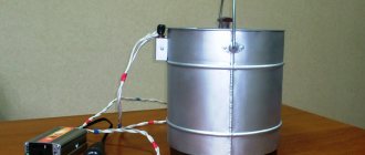
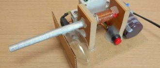
I had already created several static electricity generators before and these projects always aroused great interest. They are a lot of fun to play with and allow you to do a lot of different tricks with ESD. For example, you can shock your friends (and yourself), force sand or dust particles with your hands to behave strangely, since they are susceptible to static charges. You can also attract a stream of water, charge paper so that it sticks to the wall, and perform many other magical tricks.
The video above demonstrates the assembly process for this project, and the text version below will give you step-by-step instructions. This is the third version of my static electricity generator, and it is the cheapest. It allows you to create a charge about the same as what happens when you catch a spark from a carpet while walking on it in your pajamas.
The USB ionizer, which is the main component of the project, can be found here: link
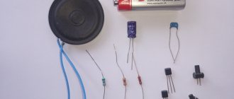
We will need:
- Ionizer.
- Insulated wire.
- Heat-shrink tubing.
- Hot glue.
- Solder and soldering iron.
- Button batteries 1.5v.
- Insulating tape.
Steven Mark's engine: another attempt or reality?
Publication date: October 17, 2019
Steven Mark's TPU Toroidal Oscillator is another type of fuel-free magnetic current amplifier MEG. The development was patented in the USA in 2006. The design involves combining a generator and a resonant transformer.
No moving parts
Inventor Stephen Mark has created a device that, once started, produces 10 times more energy than it consumes. Various consumers were powered from the device: incandescent lamps, televisions, drills. It is not yet possible to equip an energy-saving house with such technology, but there are interesting ideas for further development of this area.
Experimenters claim that some hygroscopic effect is felt during operation of the Stephen Mark engine. Plus the device gets hot. The principle of operation is hidden in resonant frequencies, current shocks in the metal and a magnetic vortex.
Attempts to repeat the invention began after the publication in Overunity of correspondence between the author of the device and journalist Lindsay. One of the experimenters noted the harmful characteristics of the three-frequency device: it negatively affects human health. Experts on the forums associate getting an increase with the use of NMR (nuclear magnetic resonance), which is costly and useless for practical use.
In the scientific community, the single-phase circuit of Stephen Mark's followers - Otto Sabjarik and Ronette - is considered safer. In it, all coils are powered from a common generator.
Features of a unique design
The inventors do not talk about the secrets of the device. But there are some manuals for assembling analogues. Let's look at them.
The design diagram contains:
- inner ring-shaped base;
- internal collector coil;
- four control coils;
- external collector coil.
The first element serves as a stable platform. There are coils on and around it. This metal ring is about 15-20 cm in diameter.
The inner coils are made of wire. They are bifilar two-wire, 90 degrees, as in a magnetic field installation. Their width should be greater than their thickness. A gap of 1.5 cm is left between the coils. The output collector is bifilar.
The coils are powered single-phase from a common generator. The output power is about 100 W. It increases subject to the safety measures that are associated with the radiation of the Stephen Mark ring in the DIY circuit.
There are no spark gaps or high-voltage circuits in the device, so it can be used for power supply and heating.
what is the minimum distance between the house and the garage
Sample Assembly Guide
There are no detailed instructions for assembling the Steven Mark generator. There are some considerations and fragmentary information from experimenters.
Particular attention is paid to the general return ground. You can use a large terminal block mounted on the TPU itself. A capacitor is also required. Without it, the entire structure will be affected by the returned radiation.
The input section must provide an interface to the oscillator plus produce synchronized square waves. The problem can be solved with a CMOS multivibrator.
Noise overlays are observed from the action of high-speed current switching. It is believed that part of this comes from the earth and the Miller effect. Electrostatic interactions with nearby circuits also have an effect. But switching occurs to a sufficient extent.
The whole secret of Stephen Mark's TPU is in the multiphase master generator. The relationship between phases and amplitudes requires precise tuning, which requires a certain amount of experience and knowledge. If these are not enough, it is wise to start experimenting with ways to obtain free electricity from the ground or reproduce simplified generator designs.
You need to be logged in to leave a comment.
DIY Toroidal Generator by Stephen Mark
DIY fuel-free generator 2-FREQUENCY TPU
Several years ago, an electrician inventor named Stephen Mark came up with a device that, once turned on, produced a fairly large amount of electricity. He called the device the Steven Mark TPU Toroidal Generator. This generator powered various consumers of electrical energy, from incandescent lamps to complex household appliances such as a TV set and an electric drill. It is noteworthy that after starting the TPU, the generator does not require any external energy supply and operates indefinitely. When working, according to the testers, a slight gyroscopic effect is felt, as well as heating of the device. Many have been able to replicate this device. The principle of operation is based on the creation of resonant frequencies, current shocks in the metal, as well as the creation of a magnetic vortex.
Previously, a video was published on our website:
2-FREQUENCY TPU BASED ON COLLISION OF ROTATING MAGNETIC FIELDS (2 freq-MAGCLASHHTPU)
Ver. 1.2 – 04-18-2007
This "single ring" TPU consists of:
Inner ring-shaped base. Internal collector coil. Four control coils. External collector coil. Inner ring-shaped base
The inner ring-shaped base serves as a stable platform on and around which all the coils will be located. In this case, to speed up production, I used 5mm compensated wood (plywood?), but of course you can use plastic or even better: expanded polyurethane sheet (commonly used for wall insulation) because it is "soft" and will help absorb vibrations from the internal manifold. Here is a picture of this wooden base.
To cut it out of a sheet, I used a jigsaw and a sheet of markings glued on top.
Inner diameter 18.0 cm.
External diameter 23.0 cm.
Internal collector coil
The internal collector coil in this version is made of 3 turns of 5 parallel Litz wires*, each Litz wire consists of 40 copper wires with a diameter of 0.05 mm. As in the following figure. In total, I got 40 * 5 = 200 leads.
This Litz wire should be placed on the base and located near the center. I just glued it to the wood to secure it.
Alternatively, I think you can use standard 1mm solid wire…. In the end, you can run 2-4 wires in parallel... or try something else.
Note: Regarding the number of turns, I used 3, but one will probably be enough.
The control coils are bifilar (two-wire). A total of 4 coils, each 90 degrees, as usual for installing a rotating magnetic field, according to patent 390721. These coils, for basic reasons, will be of the flat type, because their width is greater than their thickness. Here's a picture of these wired CCs showing clearly what I mean.
It can be seen that there is a gap of about 1.5 cm between the coils (the non-uniformity of the width of the tree is a consequence of my mistakes in making the base).
Each coil is wound with a standard single-core wire with a cross-section of 1 mm. with standard “CE” insulation. Each coil has 21 bifilar turns.
Also visible are two parallel Litz wire leads (with red Faston pins).
I advise you to pre-cut 8 wires a little over a meter long before you start winding, so that the number of turns on the coils is the same. Using different colors will also help (later) differentiate the output.
The output collector coil is also of bifilar type. I used the same wire as for CC. You need to cover the entire accessible surface.
The manifold has gaps in the picture, but I rewound it to cover the entire surface.
General Assembly Considerations
As you can see, this TPU is very simple and easy to assemble. It also weighs less than 100 grams.
I highly recommend using a wooden base (eg the same material you made the coil base from) to mount the TPU itself and lay out all the electronics, or at a minimum the required two power MOSFETs*.
That's what I mean. This is a rough example, but right now I'm interested in getting it done quickly.
TPU with fully connected wires
This diagram is divided into 4 sections:
Input section.
Driver section
Coil section.
Output section.
Particular attention should be paid to installing a common return ground. This is a must. I used a large terminal block to connect all the +VDC and all ground pins together (mount this terminal block inside or on the TPU itself).
Again, it is MANDATORY to install a 10 microfarad / 100V polyester capacitor between these two points. If you don't do this, you will see that all your equipment, starting with the PSU, will be affected by the returned radiation/currents (my PSU was powered from the TPU.). I spent a lot of time trying to get rid of this effect!!
The purpose of the input section (lower left in the drawing) is to provide an interface to the square wave generator and suitably output synchronized square waves (first and second harmonics). This problem is easily solved using a CMOS multivibrator (CMOSflip-flop (FF)).
Electric generator elements
It consists of several main parts:
- Ring-shaped base.
- Internal collector coil.
- Control coils.
- External coil.
Ring-shaped base. The internal base in the form of a ring of certain dimensions was made by the inventor from plywood, but plastic or polyurethane can be used. These materials are able to effectively absorb vibration of the internal collector.
Internal collector coil. A standard stranded copper wire with a small cross-section of 1 mm is used. Winding is performed from one to three turns.
Stephen Mark Generator Circuit
Control coils. Four flat coils. The wire is wound across the base on four sides at 90 degrees. The distance between the coils can be maintained up to 15 mm. Single-core copper wire is used as winding material.
External coil. A separate insulated wire tightly covers the entire surface of the base with coils.
EnergyScience.ru – alternative energy
Alternative energy sources
- Unanswered topics
- Active topics
- Search
- our team
Materials on Stephen Mark's technology
Materials on Stephen Mark's technology
Post by WILL » 05 Jul 2022, 11:43
Re: Materials on Steven Mark's technology
Post by doktorsvet » 06 Jul 2022, 19:10
Re: Materials on Steven Mark's technology
Post by doktorsvet » 06 Jul 2022, 19:36
Re: Materials on Steven Mark's technology
Post by Mebius » 10 Sep 2022, 12:35
Re: Materials on Steven Mark's technology
Post by Mebius » 10 Sep 2022, 12:45
Re: Materials on Steven Mark's technology
Post by WILL » 10 Sep 2022, 12:50
If you believe what Occasion1 said, then his version of the TPU had a number of very harmful characteristics, something like burning out the retina of the eye if directed strictly at the center of the TPU, and the second case is the formation of a vortex in the center of the TPU, which affects the weather and a person.
I don't know how true this is.
Re: Materials on Steven Mark's technology
Post by WILL » Sep 10, 2022, 12:53 pm
thanks for
Do-it-yourself Testatika electrostatic generator
Now there is quite a lot of information in the public domain about the appearance and operation of the device, all of it is speculative and technically complex. Over the years, the unit was demonstrated to various technicians and engineers who were invited into the community, but after 30 years, no one had ever produced a working prototype of the device so that it could be assembled outside of Methernitha. According to the Meternites, in order to understand nature and feel its voice, a person must experience silence and loneliness. After all, it was there that knowledge about this technology was obtained.
But craftsmen do not give up hope of getting free energy and are trying to recreate the creation of Paul Baumann with their own hands.
Source
Static electricity from the air
For many years, scientists have been searching for an ideal alternative source of electricity that would make it possible to extract current from renewable resources. Tesla thought about how to get static electricity from the air in the 19th century, and now scientists have come to the conclusion that yes, this is quite possible.
Types of production
Alternative electricity can be produced from the air in two ways:
- Wind generators;
- Due to the fields that permeate the atmosphere.
As is known, electric potential tends to accumulate over a certain time. Now the atmosphere is riddled with various waves produced by electrical installations, devices, and the natural field of the Earth. This allows us to say that electricity can be obtained from atmospheric air with your own hands, even without any special devices or circuits, but we will discuss the features of current production for this option below.
Photo - lightning battery
Wind generators are long-known sources of alternative energy. They work by converting wind power into current. A wind generator is a device that can operate for a long time and accumulate wind energy. This option is widely used in various countries: the Netherlands, Russia, USA. But one wind turbine can provide a limited number of electrical appliances, so entire fields of wind turbines are installed to power cities or factories. There are both advantages and disadvantages to using this method. In particular, wind is a variable quantity, so the level of voltage and accumulation of electricity cannot be predicted. At the same time, it is a renewable source, the operation of which does not harm the environment at all.
Photo - wind turbines
Video: creating electricity from thin air
How to extract energy from thin air
The simplest circuit diagram does not include any additional storage devices and converters. Essentially, all that is required is a metal antenna and ground. An electric potential is established between these conductors. It accumulates over time, so it is a variable value and it is almost impossible to calculate its strength. Such a current-generating device operates on the principle of lightning - after a certain period of time, a current discharge occurs (when the potential has reached its maximum). Thus, it is possible to extract a sufficiently large amount of useful electricity from the ground and air, which will be sufficient to operate the electrical installation. Its design is described in detail in the work: “Secrets of the free energy of cold electricity.”
Photo - diagram
The scheme has its advantages :
- Easy to implement. The experiment can be easily repeated at home;
- Availability. No tools are needed; the most ordinary plate of conductive metal will be suitable for the project.
Flaws:
- The implementation of the scheme is very dangerous. It is impossible to calculate even the approximate number of amperes, not to mention the strength of the current pulse;
- During operation, a kind of open ground loop is formed, to which lightning is attracted. This is one of the most important reasons why the project did not “go to the masses” - it is dangerous for life and production. A lightning strike sometimes reaches 2000 volts.
From this point of view, free electricity produced using wind generators is safer. But nevertheless, now you can even buy such a device (for example, the Chizhevsky ionizer-chandelier).
Photo - Chizhevsky chandelier
But there is another option for a working scheme - this is a TPU generator of electricity from the air from Steven Mark. This device allows you to obtain a certain amount of electricity to power various consumers, and it does this without any external recharge. The technology has been patented and many scientists have already repeated the experience of Stephen Mark, but due to some features of the scheme it has not yet been put into use.
The operating principle is simple: current resonance and magnetic vortices are created in the generator ring, which contribute to the appearance of current shocks in metal taps. Let's look at how to make a toroidal generator to extract electricity from the air:
- You will need a base (this could be a ring-shaped piece of plywood, a piece of rubber, polyurethane, etc.), two commutator coils (inner and outer) and control coils. An individual drawing may have other dimensions, but the base is based on a ring with an outer diameter of 230 mm, an inner diameter of 180 mm, a width of 25 mm and a thickness of 5 mm. Cut a ring of this size from the base;
Photo - base - Now you need to wind the internal collector coil. The winding is three-turn, made with stranded copper wire. Experts claim that one turn of winding will be enough to power the light bulb and conduct the experiment;
- There are four control coils, each of them must be at a right angle, otherwise interference will be created with the magnetic field. The winding is flat, the gap between the individual turns (coils) is approximately 15 mm, but this depends on the characteristics of the chosen material;
Photo - four coils - To wind the control coils, single-core copper wires can be used; it is recommended to make 21 turns for the described size;
- To install the last coil, insulated copper wire is used. It is wound over the entire base area.
Photo - final winding
How it works - theory
The rotation of disks with metal sectors leads to the transfer of electrical charge inside the machine, which is stored in capacitors until a spark or leakage charge occurs.
The most important parts in an electrophore unit are neutralizers. These are two jumpers with brushes installed in a cross. If at least one of the four brushes is moved away from the segments, the machine stops working. Although it would seem that the disks are rotating, they are electrified by friction with the air, which means electricity is generated.
The neutralizer does the following: it drags the charge from one half of the disk to the other and the disk is not just charged, but selectively charged - not over the entire plane.
In other words, the disk collects charges from the air, and the neutralizers redistribute them. The charge is removed by the brush, moves along the conductor to the opposite brush, and at the moment when a segment of the second disk appears opposite the segment, it jumps to it.
Next, this segment approaches the brush of the second neutralizer and the process is repeated, but on another disk. Thus, a circulation of charges occurs between the disks, during which the air between the segments is ionized and separated. As a result of pumping, the voltage increases; in addition, the machine has the effect of moving the capacitor plates apart, which also helps to increase the voltage.
Useful: Adjustable power supply with full digital control
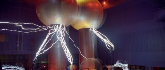
A miniature device for creating such harmless lightning (but not for microelectronics) is easy to make with your own hands.
This electrostatic generator is capable of generating over 20,000 volts, but the low current makes it safe to use without special precautions.
Is it possible to make a fuel-free energy generator with your own hands?
Many of us like to save money, so when we come across an advertisement on the Internet about the sale of a fuel-free generator (BTG), our hands reach for the “place an order” button. But will such a miracle device really help you save money?
What do fuel-free generator manufacturers promise?
On the Internet you can find various sites that offer to buy BTG, and for quite a lot of money (on average - 12 thousand rubles). Moreover, each seller explains the principle of operation of the mechanism in his own way. Some say that a fuel-free generator operates on some kind of “earth energy”, for others the source is ether, and others talk about static energy, which does not obey the known laws of physics, but is quite real.
IMPORTANT! The theory of the ether was relevant until the beginning of the twentieth century, until in 1910 Einstein refuted it in his scientific article “The Principle of Relativity and Its Consequences in Modern Physics.”
In fact, BTG is a beautiful invention, and similar devices do not exist in nature.
However, for those who are new to physics, the explanations about the ether and “earth energy” are quite enough to buy an expensive but useless generator.
Is it possible to make a fuel-free generator with your own hands?
If you are still in doubt, try assembling such a generator yourself. There are many different schemes on the Internet for collecting BTG at home. Among them, there were two fairly simple methods: wet (or oil) and dry.
Oil method of collecting BTG
- AC transformer – necessary to create constant current signals;
- Charger – ensures uninterrupted operation of the assembled device;
- Battery (or regular battery) – helps accumulate and conserve energy;
- Power amplifier – will increase the current supply;
The transformer must be connected first to the battery and then to the power amplifier. Now a charger is connected to this design, and the portable BTG is ready!
Dry method
- Transformer;
- Generator prototype;
- Undamped conductors;
- Dynatron;
- Welding.
Connect the transformer to the generator prototype using undamped conductors. Use welding for this. A dynatron is needed to control the operation of the finished device. Such a generator should work for about 3 years.
The success and effectiveness of these designs largely depends on your luck. You will also need it to find all the necessary elements specified in the instructions. But you probably already guessed that all this is unlikely to work.
Who led the development of the free energy generator
Adams generator
In 1967, a patent was received for the production of this generator. The BTG turned out to be working, but the power it produced was so small that it would hardly be possible to provide energy to even a small room with its help.
But scammers don't care. Therefore, on the Internet you can find sites selling the Adams generator. But why spend money on a device that won’t help you save money?
Tesla Generator
The life and work of the famous scientist have long been overgrown with various inventions. Nobody knows for sure which of them is true and which is fiction. And this has become an endless source of inspiration for swindlers.
Nikola Tesla really tried to invent a special device. Not a fuel-free generator, but a perpetual motion machine. But let's be realistic. Think about it, if a scientist managed to come up with such a device, would they sell it to the masses?
Hendershot Generator
Information about this device first appeared in America at the beginning of the twentieth century. But the generator became widely known during a congress dedicated to the study of the energy of the gravitational field, which was held in Toronto in 1981.
REFERENCE. There is an opinion that the physicist is not the author of the BTG. Nobody knows how and when Hendershot received the device or the schemes for its assembly.
The Hendershot generator works thanks to the earth's magnetic field, so its use causes some difficulties, because the generator must always be correctly located relative to the south and north poles of the planet.
Soon after the convention, Lester Hendershot was considered a fraud, and his device was declared a fake.
Generator by Tariel Kapanadze
Tariel Kapanadze is a Georgian inventor who, as many believe, has achieved the impossible. He invented BTG, and named it in his honor - capagen. The functionality of the device was demonstrated to the audience. But it is difficult to say whether this was a show or a demonstration of a real fuel-free generator, because Kapanadze keeps his technology secret, awaiting a rich sponsor for the further development of the project.
Despite the secrecy of the project, some sellers claim that they managed to obtain Kapanadze generator circuit diagrams, according to which they can assemble it themselves. But this is hard to believe.
Donald Smith Generator
Donald Smith is the most famous inventor of the fuelless generator. The design of the device is quite simple: a wave resonator is taken and oscillated using a spark generator. In addition, the circuit contains diodes, the function of which is completely unclear. But most importantly, where does the additional energy come from in the generator, and even in an amount of about 10 kW?
Donald Smith tried for a long time to explain the principle of operation of his invention, but they could not understand it. Many tried to replicate this device, but the power always turned out to be much less than that of the original.
Stephen Mark TPU Generator
The design of Steven Mark's device is very different from other BTGs, since the basis of the TPU generator is a metal ring with a diameter of 20 cm and coils of thick stranded wire placed on it.
REFERENCE. Stephen Mark was looking for an investor for his project for some time, but then suddenly disappeared. There is currently no information about the fate of the inventor or his device.
It is very difficult to assemble the TPU Mark generator yourself. The complexity of the design lies in the use of a multiphase master generator. In addition, neither the inventor himself nor his followers ever spoke about the principle of operation of the device.
Kulabukhov generator
Inventor Ruslan Kulabukhov came up with BTG for everyday use. But alas, he was never able to explain the operating principle of his invention, which casts doubt on the effectiveness of the device.
There are no arresters in the design of the BTG. The mechanism consists of a high-frequency cacher part and a low-frequency push-pull part. On the Internet you can find many different schemes for assembling a generator. But it was not Ruslan himself who created them, but his assistants. But few people managed to assemble a working mechanism according to these drawings, because, as mentioned above, even the author himself cannot explain the operating principle of his BTG.
Dangerous fun: an easy-to-replicate high voltage generator
Good afternoon, dear Khabrovsk residents. This post will be a little unusual. In it I will tell you how to make a simple and fairly powerful high-voltage generator (280,000 volts). I took the Marx Generator circuit as a basis. The peculiarity of my scheme is that I recalculated it for accessible and inexpensive parts. In addition, the circuit itself is easy to repeat (it took me 15 minutes to assemble it), does not require configuration and starts the first time. In my opinion, it is much simpler than a Tesla transformer or a Cockroft-Walton voltage multiplier.
Principle of operation
Immediately after switching on, the capacitors begin to charge. In my case, up to 35 kilovolts. As soon as the voltage reaches the breakdown threshold of one of the arresters, the capacitors through the arrester will be connected in series, which will lead to a doubling of the voltage on the capacitors connected to this arrester. Because of this, the remaining spark gaps are triggered almost instantly, and the voltage on the capacitors adds up. I used 12 steps, which means the voltage should be multiplied by 12 (12 x 35 = 420). 420 kilovolts are almost half-meter discharges. But in practice, taking into account all the losses, the resulting discharges were 28 cm long. The losses were due to corona discharges.
About details:
The circuit itself is simple, consisting of capacitors, resistors and arresters. You will also need a power source. Since all the parts are high-voltage, the question arises, where to get them? Now, first things first:
1 - resistors
Resistors needed are 100 kOhm, 5 watt, 50,000 volt.
I tried many factory resistors, but none could withstand such voltage - the arc would break through the top of the case and nothing would work. Careful googling yielded an unexpected answer: the craftsmen who assembled the Marx generator for voltages of more than 100,000 volts used complex liquid resistors, the Marx generator on liquid resistors, or used a lot of stages. I wanted something simpler and made resistors from wood. I broke off two even branches of a damp tree on the street (dry ones do not conduct current) and turned on the first branch instead of a group of resistors to the right of the capacitors, the second branch instead of a group of resistors to the left of the capacitors. It turned out to be two branches with many conclusions at equal distances. I made conclusions by winding bare wire over branches. Experience shows that such resistors can withstand voltages of tens of megavolts (10,000,000 volts)
2 - capacitors
Everything is simpler here. I took capacitors that were the cheapest on the radio market - K15-4, 470 pF, 30 kV (aka greensheets). They were used in tube TVs, so now you can buy them at a disassembly site or ask for them for free. They withstand a voltage of 35 kilovolts well, not a single one has broken through.
3 - power supply
I just couldn’t bring myself to assemble a separate circuit to power my Marx generator.
Because the other day my neighbor gave me an old TV “Electron TC-451”. The anode of the kinescope in color televisions uses a constant voltage of about 27,000 volts. I disconnected the high-voltage wire (suction cup) from the anode of the kinescope and decided to check what kind of arc would be produced from this voltage. Having played enough with the arc, I came to the conclusion that the circuit in the TV is quite stable, can easily withstand overloads, and in the event of a short circuit, the protection is triggered and nothing burns out. The circuit in the TV has a power reserve and I managed to overclock it from 27 to 35 kilovolts. To do this, I twisted the R2 trimmer in the TV power module so that the horizontal power supply rose from 125 to 150 volts, which in turn led to an increase in the anode voltage to 35 kilovolts. When you try to increase the voltage even more, the KT838A transistor breaks through in the horizontal scan of the TV, so you need to not overdo it.
Build process
Using copper wire, I screwed the capacitors to tree branches.
There must be a distance of 37 mm between the capacitors, otherwise an unwanted breakdown may occur. I bent the free ends of the wire so that there was 30 mm between them - these will be the arresters. It's better to see once than to hear 100 times. Watch the video where I showed in detail the assembly process and operation of the generator:
Safety precautions
Particular care must be taken, since the circuit operates at a constant voltage and a discharge from even one capacitor will most likely be fatal.
When turning on the circuit, you need to be at a sufficient distance because electricity penetrates 20 cm or even more through the air. After each shutdown, you must always discharge all capacitors (even those in the TV) with a well-grounded wire. It is better to remove all electronics from the room where the experiments will be carried out. The discharges create powerful electromagnetic pulses. The phone, keyboard and monitor that are shown in my video are out of order and can no longer be repaired! Even in the next room my gas boiler turned off.
You need to protect your hearing. The noise from the discharges is similar to gunshots, then it makes your ears ring.
Interesting observations
The first thing you feel when you turn it on is how the air in the room is electrified.
The electric field intensity is so high that it is felt by every hair of the body. The corona discharge is clearly visible. Beautiful bluish glow around parts and wires. There is always a slight electric shock, sometimes you don’t even understand why: you touched the door - a spark jumped, you wanted to take the scissors - the scissors shot. In the dark, I noticed that sparks were jumping between various metal objects not connected with the generator: in a briefcase with a tool, sparks were jumping between screwdrivers, pliers, and a soldering iron.
The lights light up on their own, without wires.
The whole house smells like ozone, like after a thunderstorm.
Conclusion
All parts will cost about 50 UAH ($5), this is an old TV and capacitors.
Now I am developing a fundamentally new scheme with the goal of obtaining meter discharges without special costs. You ask: what is the application of this scheme? I will answer that there are applications, but they need to be discussed in another topic. That's all for me, be careful when working with high voltage.